Force Selector
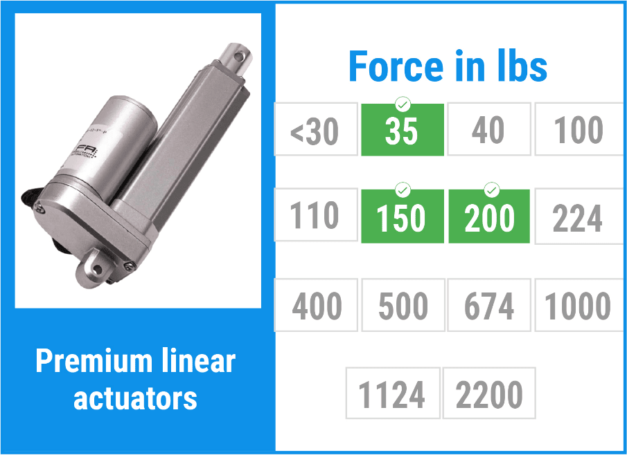
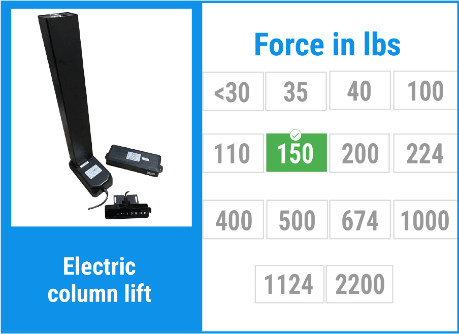
Use this force selector as a practical starting point for choosing a FIRGELLI linear actuator by rated force. The green values shown on the actuator images identify the force options available for each model family. Click an image to review that product series, then confirm stroke, speed, mounting style, feedback, duty cycle, and environmental requirements before ordering.
Force selection is not just a matter of matching the weight of the object being moved. The actuator must overcome the working load, friction, linkage geometry, acceleration, side loading caused by imperfect alignment, and any extra resistance that appears near the end of travel. A hatch, trap door, drawer slide, scissor lift, solar panel, medical-style adjustment, or hidden automotive feature can all require very different actuator forces even when the visible load weight is the same.
If you already know the stroke but not the force, this page helps narrow the product family. If the geometry is still unknown, start with the Linear Motion Calculator or the guide to measuring actuator force. For a broader explanation of how force and stroke options relate across actuator families, see the Linear Actuator Force and Stroke Guide.
What is Covered in This Force Selector
Actuator Families and Available Force Options
The product images below are the original selector tiles for this page. Use the green-highlighted force values on each image to quickly compare which actuator series are available in the force range you need. Product pages contain the current detailed specifications for each model, including stroke choices, speed, current draw, feedback options, limit switch behavior, and mounting accessories.






How to Use the Force Selector Correctly
Start by estimating the real force at the actuator, not only the weight of the load. For a straight horizontal push with low-friction guides, the actuator may mainly overcome rolling or sliding friction. For a hinged lid, the required force changes throughout travel because the actuator angle and lever arm change. For a vertical lift, the actuator must support gravity directly, and the selected force should include margin for static friction, seal drag, and any binding in the guide system.
A practical workflow is: define the load case, draw the mounting points, measure the worst-case angle, calculate the peak force, then choose the nearest actuator family with suitable stroke and speed. If the load is safety-critical or could injure someone, do not size by guesswork. Prototype the mechanism, measure current draw under load, and verify that the structure, pivots, brackets, and controller are all rated for the forces involved.
As a rule of thumb for early concept work, many builders begin with a service factor above the calculated ideal load. The correct margin depends on the application. A clean indoor cabinet door may need modest margin, while an outdoor hatch, dusty slide, vehicle mechanism, or linkage with changing geometry may require much more. More force is not automatically better: a higher-force actuator is often slower, may draw more current, and can damage a lightweight frame if the limit switches or controls are not set up correctly.
Engineering Assumptions That Change the Required Force
Mounting geometry: The actuator is strongest when its line of action is aligned with the required motion. If it pushes at a shallow angle near a hinge, only part of its rated force creates useful torque. The first few degrees of opening are often the worst case for lids and covers.
Friction and guide quality: Drawer slides, bushings, rollers, and tracks can add a surprising amount of resistance, especially when loaded unevenly. If a mechanism works by hand only when pulled from one exact spot, it is probably asking the actuator to fight side load or racking.
Static versus dynamic load: Starting force is commonly higher than running force. A design that barely moves once it is already in motion may stall from rest. Test the worst position, not the easiest position.
Speed tradeoff: In electric linear actuators, higher force usually comes with lower speed for the same voltage and motor package. If the application needs both high force and fast travel, review the speed versus force tradeoff calculator before locking in the design.
Feedback and synchronization: If two actuators lift the same platform, force rating alone is not enough. Consider feedback actuators and a controller strategy that keeps both sides moving together. A rigid platform driven by unsynchronized actuators can twist, jam, or overload one side.
Application-Based Force Selection Guide
| Application type | Primary force driver | What to check before selecting | Helpful FIRGELLI resource |
|---|---|---|---|
| Hinged lid, hood, or trap door | Torque around the hinge and actuator angle at the worst position | Measure hinge-to-load center distance, actuator bracket positions, and the opening angle where force peaks | Linear Motion Calculator |
| Vertical lift or column-style movement | Direct weight plus friction and guide resistance | Confirm total moving mass, guide alignment, duty cycle, and whether the actuator must hold position when power is removed | How to Measure Linear Actuator Force |
| Sliding drawer, panel, or rail system | Static friction, racking, and off-center loading | Test the slide by pulling from the proposed actuator location and inspect for binding at full extension | Friction Force Calculator |
| Inclined plane, ramp, or solar panel tilt | Gravity component down the slope plus friction | Confirm slope angle, load weight, coefficient of friction estimate, wind or external loads, and travel stops | Inclined Plane Force Guide |
| Scissor lift | Low mechanical advantage near the collapsed position | Calculate force at the lowest starting height; this is usually the highest required force point | Scissor Lift Calculator |
| Automotive or custom show mechanism | Packaging limits, vibration, weather exposure, and bracket stiffness | Mock up the brackets, test with the real panel weight, and leave room for wiring strain relief | 1952 Chevy Truck Actuator Build |
Worked Sizing Examples
Example 1: Small horizontal sliding panel
Assume a 40 lb panel moves on good linear slides and a pull test shows it starts moving at about 12 lb of force. If the actuator is mounted in line with the slide, the required actuator force is close to that measured start force, plus margin. A compact actuator with a force rating comfortably above the measured requirement may be appropriate, provided the stroke, speed, and duty cycle match. If the same actuator is mounted off-center and the panel racks, the force requirement can climb quickly. The fix is often better guide spacing or a centered push point, not simply a larger actuator.
Example 2: Hinged hatch that is hard to start
Assume a hatch weighs 80 lb and its center of gravity is 18 inches from the hinge. The hatch creates 1,440 lb-in of torque when horizontal. If the actuator bracket geometry only gives an effective perpendicular lever arm of 4 inches at the closed position, the actuator may need roughly 360 lb before friction and margin. Moving the bracket to increase the lever arm can reduce the actuator force dramatically. This is why a 100 lb actuator may work perfectly in one hatch layout while a 400 lb actuator struggles in another.
Example 3: Inclined surface
Assume a 100 lb load moves up a 30 degree incline. Ignoring friction, the gravity component along the slope is about 50 lb. Add sliding friction and a design margin and the selected actuator may need to be well above 50 lb. If the ramp is dirty, exposed to weather, or uses plain sliding contact instead of rollers, test the real mechanism before committing to the final force rating.
Common Force Selection Mistakes to Avoid
- Choosing force from load weight alone. A 100 lb load can require less than 20 lb on a good horizontal roller system or several hundred pounds through a poor hinge geometry.
- Ignoring the worst position. The actuator may need peak force at the start, middle, or end of travel depending on linkage geometry. Check the entire range.
- Using the actuator as a structural guide. Linear actuators are designed for axial push and pull. Side load shortens life and can cause binding. Use rails, pivots, or guides to carry side forces.
- Oversizing without checking structure. A high-force actuator can bend brackets, crack panels, or overload hinges. The frame must be stronger than the actuator force path.
- Forgetting electrical capacity. Higher loads increase current draw. Verify power supply, wire gauge, controller rating, fuse sizing, and voltage drop under load.
- Assuming two actuators will self-synchronize. If one side moves faster, the structure can twist. Use feedback and appropriate control when synchronized motion matters. The Arduino actuator control guide is a useful starting point for custom control concepts.
Final Checks Before You Choose an Actuator
Before selecting a product from the force selector, write down five numbers: required stroke, calculated or measured peak force, desired speed, voltage available, and expected duty cycle. Then check the physical package: retracted length, extended length, bracket clearance, wire routing, and whether the actuator body will collide with the mechanism through the full motion.
If your application falls between standard models or requires a special stroke, feedback arrangement, connector, or mounting package, review Custom Linear Actuators. For more complex mechanisms, the Free Engineering Calculators page collects additional tools for force, torque, stress, and motion estimates.
Force Selector FAQ
Should I choose the next higher force rating if my calculation is close?
Usually yes, provided the slower speed, current draw, and stronger mounting requirements are acceptable. Do not choose a higher force actuator as a substitute for poor alignment or weak brackets. Fix the mechanism first, then add reasonable margin.
Why does a high-force actuator move slower?
For a given motor and voltage, force and speed trade against each other through gearing and screw pitch. Higher-force models typically use more mechanical advantage, which increases push or pull capacity but reduces travel speed.
Can I use two smaller actuators instead of one larger actuator?
Sometimes, but only if the structure and controls are designed for it. Two actuators can share load, but they can also fight each other if one moves faster or sees more resistance. Use feedback or a synchronization controller when uneven motion would cause binding.
How much safety factor should I use?
There is no universal number because the right margin depends on geometry, friction, shock loading, environment, and consequence of failure. For non-critical prototypes, start with measured force plus margin and validate by testing. For equipment where failure could injure people or damage property, have the design reviewed against the applicable standards for that machine.
What if I do not know the load force yet?
Build a simple test fixture or use a scale to measure the push or pull force at the intended actuator mounting point. Measure from rest, through the entire travel, and in the worst expected condition. That real measurement is often more useful than a perfect-looking calculation based on uncertain friction values.