Understanding Compound Levers: Amplifying Force Through Mechanical Advantage
In the world of mechanical engineering and motion control systems, few principles are as fundamental or powerful as the compound lever. While simple levers have served humanity for thousands of years, compound lever systems take the concept of mechanical advantage to an entirely new level by cascading multiple levers together. Whether you're designing heavy machinery, developing precision hand tools, or engineering automated systems with linear actuators, understanding how compound levers work is essential for maximizing force output while minimizing input effort.
A compound lever system consists of two or more simple levers working in series, where the output force or motion from one lever becomes the input force or motion for the next. This arrangement creates a multiplicative effect on mechanical advantage, allowing operators to move loads that would be impossible with a single lever alone. From industrial punch presses capable of shearing through steel plate to the humble can opener in your kitchen drawer, compound levers are everywhere—often working invisibly to make difficult tasks effortless.
This comprehensive guide explains the mechanics, mathematics, and practical applications of compound lever systems. We've also included an interactive calculator to help you determine the exact mechanical advantage and output force for your specific compound lever configuration, whether you're prototyping a new design or optimizing an existing mechanism.

How Compound Levers Work: Step-by-Step Mechanics
The fundamental operation of a compound lever system follows a logical sequence of force transmission and amplification. Understanding each step in this process is crucial for both designing new systems and troubleshooting existing ones.
The Force Transmission Sequence
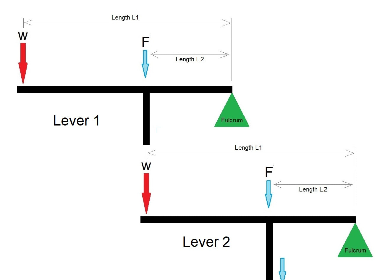
The process begins when an operator applies an effort force (input force) to the first lever in the system. This initial lever amplifies the input force based on its mechanical advantage, which is determined by the ratio of the lengths of its effort arm (the distance from the applied force to the fulcrum) and load arm (the distance from the fulcrum to the output point).
The amplified force from the first lever then becomes the input force for the second lever. This is the key principle that distinguishes compound levers from simple levers—the output of one stage becomes the input of the next. The second lever further amplifies this already-amplified force based on its own mechanical advantage ratio.
If the system includes additional levers, the force continues to cascade through each stage, being multiplied at every step. The final lever in the chain applies the total amplified output force to the load, making it possible to move objects or perform work that would require far greater initial effort with a single lever.
Mechanical Advantage Multiplication
What makes compound levers particularly powerful is that their mechanical advantages multiply rather than add. If the first lever has a mechanical advantage of 5:1 and the second lever has a mechanical advantage of 4:1, the total system mechanical advantage is 20:1 (5 × 4), not 9:1 (5 + 4). This multiplicative effect allows compound lever systems to achieve mechanical advantages of 50:1, 100:1, or even higher with just a few stages.
This principle is particularly relevant when designing systems that incorporate industrial actuators, where combining lever mechanics with electric actuation can create extremely powerful and precise motion control systems.
Calculating Compound Lever Mechanical Advantage and Output Force
Determining the performance of a compound lever system requires understanding both the individual lever calculations and how they combine to create the total system output. The mathematics, while straightforward, must be applied correctly to ensure accurate predictions of system behavior.
Single Lever Mechanical Advantage Formula
For any individual lever in a compound system, the mechanical advantage (MA) is calculated using the following formula:
MA = Distance from Effort to Fulcrum (DE) / Distance from Load to Fulcrum (DL)
This ratio tells you how many times the lever amplifies the input force. For example, if the effort arm is 300mm and the load arm is 50mm, the mechanical advantage is 6:1, meaning the lever multiplies the input force by a factor of 6.
Total System Mechanical Advantage
For a compound lever system with two levers, calculate the mechanical advantage of each lever individually, then multiply them together:
Total MA = MA of Lever 1 × MA of Lever 2
For systems with more than two levers, extend this multiplication through all stages:
Total MA = MA of Lever 1 × MA of Lever 2 × MA of Lever 3 × ... × MA of Lever n
Calculating Output Force
Once you know the total mechanical advantage, determining the output force is straightforward. Simply multiply the total mechanical advantage by the input force:
Output Force (F_out) = Total MA × Input Force (F_in)
For example, if your compound lever system has a total mechanical advantage of 25:1 and you apply 10 kg of input force, the theoretical output force would be 250 kg.
Real-World Efficiency Considerations
It's important to note that these calculations assume an ideal, frictionless system with 100% efficiency. In practice, friction at the fulcrums, material flexing, and other inefficiencies will reduce the actual output force. Typical compound lever systems operate at 70-90% efficiency depending on construction quality, bearing type, and lubrication. When designing systems that combine levers with feedback actuators for automated control, accounting for these efficiency losses is critical for proper sizing and performance prediction.

Interactive Compound Lever Calculator
Use this calculator to determine the mechanical advantage and output force for your compound lever system. Enter the dimensions of each lever and your input force to see the results instantly.
Lever 1
Distance from Effort to Fulcrum (L1):
Distance from Load to Fulcrum (L2):
Lever 2
Distance from Effort to Fulcrum (L1):
Distance from Load to Fulcrum (L2):
Input Force
Input Force:
Results
Practical Applications of Compound Lever Systems
Compound levers appear in a surprising variety of applications, from massive industrial equipment to precision hand tools. Understanding where and why they're used helps engineers and designers recognize opportunities to apply this mechanical principle in new contexts.
Industrial Punch Presses and Stamping Equipment
One of the most common industrial applications of compound levers is the punch press, used extensively in metal fabrication and manufacturing facilities worldwide. These machines must generate enormous forces—often many tons—to shear through steel plate, punch holes, or stamp complex shapes. A human operator, however, can only comfortably apply forces in the range of 10-50 kg continuously.
Compound lever punch presses solve this problem by cascading multiple lever stages to achieve mechanical advantages of 20:1, 50:1, or even 100:1. This allows an operator applying moderate force to generate the thousands of kilograms of force required to punch through thick steel plate. The predictable, controllable nature of lever mechanics also provides important safety advantages over alternatives like hydraulic systems.
Modern punch presses often combine compound lever mechanics with linear actuators for automated operation, using the actuator to apply the input force while the lever system provides the necessary force multiplication. This hybrid approach offers the best of both worlds: electric control precision with mechanical force amplification.
Hand Tools and Manual Equipment
Many hand tools employ compound lever principles to make difficult tasks manageable with human strength alone:
- Bolt cutters: Use compound levers to generate the extreme force needed to sever hardened steel bolts and chains
- Compound snips: Sheet metal cutting tools that multiply hand force to cleanly shear through thick metal
- Heavy-duty pliers: Crimping and cutting pliers that use multiple lever stages for maximum force
- Can openers: Simple compound lever systems that make opening cans effortless
- Nutcrackers: Classic examples of compound levers designed to concentrate force on a small area
Lifting and Positioning Systems
Compound levers are frequently incorporated into lifting equipment and positioning systems where space constraints prevent the use of long single levers. Applications include:
- Scissor lifts and jack stands that use cascading levers to achieve high lift ratios in compact packages
- Adjustable desk mechanisms, including standing desk systems that combine lever mechanics with actuator drive
- Heavy equipment controls where operator comfort requires short lever arms but high forces are needed
- TV lift mechanisms that use lever stages to reduce actuator force requirements
Automation and Motion Control
In modern automation systems, compound levers are often paired with electric actuation to create powerful, precise motion control systems. By using a micro linear actuator or bullet actuator as the input force, combined with compound lever mechanics for force multiplication, engineers can create compact systems that achieve both high force and precise positioning control.
This approach is particularly valuable when using feedback actuators that provide position sensing, as the lever system multiplies both the force and the positioning accuracy of the actuator.
Design Considerations for Compound Lever Systems
Successfully implementing a compound lever system requires careful attention to several critical design factors that affect performance, reliability, and longevity.
Fulcrum Design and Bearing Selection
The fulcrums in a compound lever system are subjected to enormous forces—far greater than the input or even output forces due to the leverage geometry. Each fulcrum must be designed with appropriate bearings, bushings, or pivot mechanisms to handle these loads while minimizing friction.
High-quality linear bearings and rotary bearings at fulcrum points can significantly improve system efficiency. The difference between a system using simple pin joints versus precision roller bearings can be 20-30% or more in output force due to reduced friction losses.
Material Selection and Structural Integrity
Lever arms themselves must be rigid enough to transmit force without excessive flexing. Material selection depends on the force levels involved:
- Low-force applications (under 100 kg): Aluminum alloys or high-strength plastics may be adequate
- Medium-force applications (100-1000 kg): Steel is typically required, with cross-sectional dimensions calculated to prevent bending
- High-force applications (over 1000 kg): Heat-treated alloy steel with appropriate safety factors is essential
Any flexing in the lever arms represents wasted energy and reduced efficiency. It also introduces positioning errors in applications where precision matters.
Lever Ratio Optimization
While it might seem that maximizing mechanical advantage is always desirable, there are important tradeoffs to consider. As mechanical advantage increases, the distance the input must move to produce a given output movement also increases proportionally. A 50:1 mechanical advantage means the input must move 50 times farther than the output.
In applications using track actuators or other electric actuation, this affects actuator stroke length requirements and cycle time. The optimal design balances force multiplication needs with practical stroke and speed requirements.
Safety Factors and Overload Protection
Compound lever systems can generate surprisingly high forces, and all components must be designed with appropriate safety factors. Industrial applications typically use safety factors of 3:1 to 5:1, meaning components are designed to withstand three to five times the maximum expected load.
Overload protection mechanisms—such as shear pins, clutches, or electronic force limiting when using control boxes with feedback actuators—can prevent equipment damage and improve operator safety.
Integrating Compound Levers with Electric Linear Actuators
Modern motion control applications increasingly combine compound lever mechanics with electric linear actuators to create powerful, automated systems that benefit from both technologies.
Benefits of Hybrid Lever-Actuator Systems
Combining levers with electric actuation offers several compelling advantages:
- Reduced actuator size and cost: The lever system multiplies actuator force, allowing use of smaller, less expensive actuators
- Improved precision: Lever systems can also multiply positioning resolution when properly designed
- Enhanced control: Electric actuation with remote control provides automation capabilities while levers provide mechanical advantage
- Energy efficiency: Smaller actuators consume less power while still delivering high output forces
- Compact packaging: Lever staging can achieve high forces in constrained spaces
Actuator Selection for Lever Systems
When selecting an actuator to drive a compound lever system, consider these factors:
- Input force required: Calculate this by dividing your desired output force by the total mechanical advantage
- Stroke length needed: Remember that the actuator must move farther than the output by a factor equal to the mechanical advantage
- Speed requirements: Higher mechanical advantages mean slower output speeds for a given actuator speed
- Duty cycle: Continuous operation applications may require industrial actuators with higher duty cycle ratings
- Mounting requirements: Ensure appropriate mounting brackets are available for your configuration
Power Supply Considerations
Proper power supply sizing is critical for lever-actuator systems. While the lever reduces the force requirement on the actuator, peak current draw can still be substantial during stall or high-load conditions. Select power supplies with adequate current capacity and include appropriate overload protection.
Troubleshooting and Optimizing Compound Lever Performance
Even well-designed compound lever systems can underperform if not properly maintained or if certain common issues develop over time.
Common Performance Issues
- Insufficient output force: Often caused by friction at fulcrums, misalignment, or binding. Lubrication and alignment checks typically resolve this
- Excessive play or slop: Worn bearings or bushings allow movement that doesn't contribute to useful work. Replace worn components
- Lever arm bending: If levers flex visibly under load, they need to be replaced with more rigid materials or larger cross-sections
- Uneven force delivery: Can indicate binding or friction at one or more pivot points requiring service
- Noise or vibration: Typically indicates worn bearings, loose fasteners, or component interference requiring inspection
Maintenance Best Practices
Regular maintenance significantly extends compound lever system life and maintains performance:
- Lubricate all pivot points according to bearing manufacturer specifications
- Inspect for wear at fulcrums and load application points quarterly or per duty cycle
- Check fastener torque regularly, particularly in high-vibration environments
- Monitor for material fatigue or stress cracking in high-load applications
- Keep actuators and mechanical components clean and free of debris
Conclusion
Compound lever systems represent one of the most elegant and effective solutions for force multiplication in mechanical design. By cascading multiple simple levers, engineers can achieve remarkable mechanical advantages that make difficult tasks manageable, whether through manual operation or automated systems driven by electric actuators.
The mathematics governing compound levers are straightforward yet powerful, allowing designers to precisely predict system performance and optimize configurations for specific applications. When combined with modern electric actuation technology, compound levers enable compact, powerful, and controllable motion systems across countless applications from industrial manufacturing to consumer products.
Whether you're designing a new mechanism, optimizing an existing system, or simply trying to understand the forces at work in a compound lever application, the principles and calculations outlined in this guide provide the foundation for success. Use the calculator provided to experiment with different configurations and discover the optimal solution for your specific requirements.
Frequently Asked Questions
What is the difference between a compound lever and a simple lever?
A simple lever consists of a single rigid bar pivoting on one fulcrum, providing mechanical advantage based on the ratio of its effort arm to load arm. A compound lever system uses two or more simple levers working in series, where the output of one lever becomes the input for the next. This cascading arrangement multiplies the mechanical advantages together rather than adding them, creating far greater total force multiplication. For example, two levers each with 5:1 mechanical advantage create a 25:1 compound advantage, not 10:1.
How do I calculate the input force required for a desired output force?
To calculate the required input force, first determine your compound lever system's total mechanical advantage by multiplying the individual mechanical advantages of each lever stage. Then divide your desired output force by this total mechanical advantage. For example, if you need 500 kg of output force and your compound lever has a total mechanical advantage of 20:1, you would need to apply 25 kg of input force (500 ÷ 20 = 25). Remember to add a safety margin to account for friction and mechanical inefficiencies, which typically reduce actual performance by 10-30%.
Why is my compound lever producing less force than calculated?
The most common reason for reduced output force is friction and mechanical inefficiency at the fulcrum points and lever connections. Theoretical calculations assume frictionless pivots, but real-world systems experience energy losses from bearing friction, material flexing, and misalignment. Systems with worn bearings, inadequate lubrication, or binding components can lose 30-40% or more of their theoretical force output. Other factors include lever arm flexing under load (which effectively reduces mechanical advantage) and loose or worn connections that create play in the system. Regular maintenance, quality bearings, and proper alignment typically recover most of this lost performance.
Can I add more lever stages to increase mechanical advantage further?
Yes, you can theoretically add as many lever stages as needed to achieve your desired mechanical advantage. However, each additional stage adds weight, cost, complexity, and additional points of friction. More stages also require proportionally greater input movement distance—a 100:1 mechanical advantage means your input must move 100 times farther than your output. Practical compound lever systems typically use 2-4 stages. Beyond this, alternative force multiplication methods like hydraulic or pneumatic systems, or simply using larger electric actuators, may be more practical and cost-effective solutions.
What type of linear actuator works best with compound lever systems?
The optimal actuator depends on your application requirements, but industrial-grade linear actuators with position feedback are typically ideal for compound lever applications requiring automation. The lever system reduces the force requirement on the actuator, often allowing use of smaller, more affordable units. For precise positioning applications, feedback actuators provide critical information about actuator position that can be used for accurate control despite the lever magnification. For heavy-duty applications, industrial actuators offer higher force capacity and longer duty cycles. When space is limited, micro linear actuators can be paired with higher mechanical advantage lever systems to achieve significant output forces in compact packages. Always ensure your selected actuator has sufficient stroke length—remember that the actuator must travel farther than the output by a factor equal to your mechanical advantage ratio.
How often should compound lever systems be maintained?
Maintenance frequency depends on duty cycle and operating conditions, but general guidelines include lubricating pivot points every 3-6 months for moderate use applications, or more frequently for continuous-duty industrial applications. Inspect bearings and bushings quarterly for wear, checking for play or roughness in movement. In high-load applications, examine lever arms and mounting points monthly for signs of stress, cracking, or deformation. Check fastener torque after initial break-in (typically 40-80 hours of operation) and then quarterly thereafter. Systems operating in dirty, dusty, or corrosive environments require more frequent inspection and cleaning. Well-maintained compound lever systems can operate reliably for decades, while neglected systems may fail in months under heavy use.


