Dual Control Systems for Linear Actuators: Combining Switches and Remotes
In many linear actuator applications, flexibility in control methods isn't just convenient—it's essential. Whether you're designing a motorized TV lift with both wall switch and remote capability, installing a basement hatch with controls on multiple floors, or creating a backup control method for critical automation systems, understanding how to wire multiple control inputs correctly can make the difference between a professional installation and a frustrating failure.
The challenge lies not just in connecting multiple switches, but in doing so safely. Without proper circuit protection, activating two control inputs simultaneously can damage sensitive electronics, create short circuits, or simply prevent your linear actuator from functioning. This tutorial provides three proven wiring configurations for dual control systems, each designed for specific use cases and reliability requirements. We'll cover the proper use of diodes for circuit protection, relay configurations, and switch selection criteria to ensure your multi-input control system operates safely and reliably.
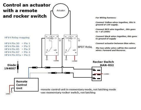
Method 1: Remote Control and Rocker Switch with Diode Protection
This configuration represents the most robust approach for combining wireless control with traditional manual switches. It's ideal for applications where you want the convenience of remote control operation while maintaining a reliable backup switch—common in TV lift systems, motorized cabinets, and accessibility applications.
Why Diodes Are Critical in This Configuration
Diodes serve as electrical one-way valves in this circuit, preventing current from flowing backward into the remote control board when the rocker switch is activated. Without this protection, voltage from the rocker switch circuit could damage the sensitive electronics in your wireless receiver. The four diodes create isolated pathways that allow either control method to operate the relays independently without interfering with each other's circuitry.
When selecting diodes for this application, use 1N4001 or higher-rated rectifier diodes. These are readily available from electronics suppliers and can handle the typical 12V or 24V systems used in linear actuator applications. The diode orientation is absolutely critical—the banded end (cathode) must be positioned as shown in the wiring diagram to ensure proper current flow direction.
Required Components
- Two SPDT (Single Pole, Double Throw) relays rated for your actuator's current draw
- Relay harness compatible with your chosen relays
- Wireless remote control system (must be set to momentary mode)
- Momentary rocker switch (not sustaining/latching type)
- Four rectifier diodes (1N4001 or equivalent)
Understanding Momentary vs. Sustaining Switches
This configuration requires momentary switches on both the rocker switch and the remote control. A momentary switch only completes the circuit while actively pressed—it springs back to the neutral position when released. This is essential because if both control inputs attempt to send opposing commands simultaneously (one extend, one retract), the actuator will receive conflicting signals and remain stationary. Momentary operation ensures that commands are intentional and brief, reducing the risk of conflict.
Most wireless remote systems for linear actuators offer both momentary and latching modes. Verify your remote is configured for momentary operation before wiring this circuit. Consult your remote control's documentation for the specific procedure to select momentary mode.
Installation Tips and Best Practices
When wiring this configuration, use appropriately sized wire for your actuator's current draw—typically 18 AWG for actuators drawing up to 6 amps, or 16 AWG for higher-current applications. Keep wire runs as short as practical to minimize voltage drop. Secure all diode connections with heat-shrink tubing or electrical tape to prevent accidental shorts.
Test the system thoroughly before final installation. Verify that the remote control operates the actuator correctly, then test the rocker switch independently. Confirm that attempting to use both simultaneously results in no movement rather than erratic behavior, which would indicate a wiring error.
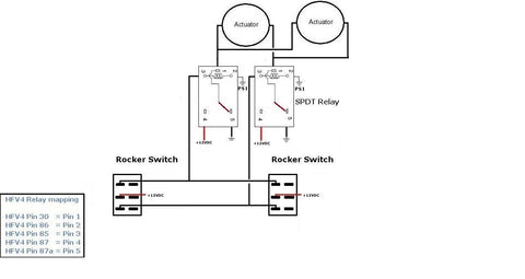
Method 2: Dual Rocker Switch Control
This configuration enables actuator control from two separate physical locations using hardwired switches. It's particularly valuable in multi-level installations such as basement hatches, attic access systems, or any application where users need control access from different areas.
Practical Applications for Dual Switch Control
The classic example is a basement access hatch where one switch is mounted at ground level and another in the basement. This allows the hatch to be operated from either location without requiring someone to move between floors. Other applications include:
- Motorized windows with control switches at different room entrances
- Industrial workbenches with adjustable height controls at both ends
- Vehicle camper tops with interior and exterior control access
- Storage loft systems with controls at ladder top and bottom
- Accessibility applications where multiple family members need convenient access
Required Components
- Two SPDT relays rated for your actuator's voltage and current
- Relay harness
- Two momentary rocker switches (SPDT configuration)
- Appropriate gauge wire for connecting distant switch locations
Choosing the Right Switches
As with the previous configuration, momentary operation is strongly recommended. This prevents situations where someone at location A extends the actuator while someone at location B attempts to retract it—a scenario that would create opposing relay commands and stall the actuator. Momentary switches ensure clear, intentional control commands.
For long wire runs between switches, consider the voltage drop over distance. If switches are separated by 20 feet or more, use 16 AWG wire even for lower-current actuators. For runs exceeding 50 feet, calculate expected voltage drop based on your wire gauge and actuator current draw to ensure reliable operation.
Wiring Best Practices for Multi-Location Control
When running wires between floors or across long distances, use proper cable management techniques. Secure cables away from sharp edges, heat sources, and areas where they might be pinched or damaged. In walls, use appropriate conduit or cable protection. Label both ends of each wire during installation to simplify troubleshooting later.
This configuration doesn't require diodes because both switches are the same type of component operating at the same voltage levels. The relay isolation prevents any issues with conflicting commands—if opposing signals are sent simultaneously, the relays simply don't activate and the actuator remains stationary.
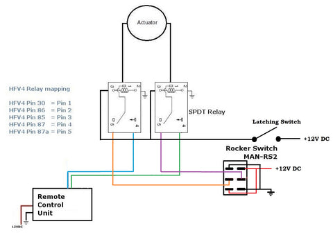
Method 3: Remote Control and Rocker Switch Without Diodes
While the diode-protected configuration in Method 1 is recommended for most applications, this alternative approach uses a latching selector switch to choose between control methods. This can be useful when you want clear, deliberate selection between remote and manual control—for example, in applications where remote control is the primary method but a manual override is needed for maintenance or emergencies.
Understanding the Selector Switch Operation
The latching switch in this configuration acts as a manual selector between two control pathways. When the latching switch is in the open position, the remote control circuit is active and can operate the actuator. When the latching switch is closed, it completes the rocker switch circuit path while simultaneously breaking the remote control path. This ensures only one control method is active at any given time, eliminating the need for diodes.
This approach offers a clear advantage in certain scenarios: the user must make a conscious decision about which control method to use by physically toggling the selector switch. This can prevent accidental remote activation during maintenance when manual control is preferred, or vice versa.
Required Components
- Two SPDT relays
- Relay harness
- Wireless remote control (can be set to either momentary or latching mode)
- Rocker switch (momentary or sustained, depending on preference)
- Latching selector switch (SPST or SPDT)
When to Choose This Configuration
This method is most appropriate when:
- You want deliberate, manual selection between control methods
- The control panel location makes a selector switch easily accessible
- You prefer not to source and install diodes
- Your application requires "lockout" capability to disable remote control
- You're integrating with existing systems that already use selector switches
However, consider that this approach requires an extra physical switch and an additional user action (selecting the control mode) before operating the actuator. For applications requiring quick, seamless switching between control methods, the diode-protected configuration in Method 1 offers more convenience.
Selecting the Right Relays for Your Application
All three configurations require SPDT relays rated appropriately for your linear actuator's specifications. Understanding relay ratings is crucial for reliable, safe operation.
Voltage Considerations
Match your relay coil voltage to your control voltage (typically 12V DC for most linear actuator systems). The relay contact voltage rating must meet or exceed your actuator's supply voltage. Most standard automotive-style relays are rated for 12V DC coil operation with 30A or 40A contacts, which is more than adequate for typical linear actuator applications.
Current Capacity Requirements
Your relay contacts must handle the actuator's peak current draw. Standard linear actuators typically draw between 2A and 6A under load, though industrial actuators may draw significantly more. Use relays with contact ratings at least 50% higher than your actuator's maximum current draw to ensure longevity and prevent contact welding.
For example, if your actuator draws 4A under maximum load, use relays rated for at least 6A continuous current. The safety margin accounts for inrush current (which can be 2-3 times running current) and prevents premature relay failure.
Understanding SPDT Configuration
SPDT (Single Pole, Double Throw) relays have one common terminal and two output terminals. When the relay is not energized, the common connects to the Normally Closed (NC) terminal. When energized, the common switches to the Normally Open (NO) terminal. This configuration is ideal for reversing linear actuator direction because it allows you to switch the polarity of the voltage applied to the actuator motor.
Two SPDT relays working together create an H-bridge configuration that safely reverses actuator direction. This is why all three methods shown require two relays—one controls the positive connection, the other controls the negative connection, and together they enable forward and reverse operation.
Power Supply Requirements for Multi-Input Systems
When implementing any of these dual control configurations, ensure your power supply can handle the combined current requirements of your actuator, relays, and wireless receiver (if applicable).
Calculating Total Current Draw
Add up the current requirements:
- Linear actuator under load: typically 2-6A (check your specific model specifications)
- Relay coil current: approximately 75-150mA per relay (two relays = 150-300mA total)
- Wireless receiver: typically 20-50mA in standby, up to 100mA when transmitting
For a typical setup with a 4A actuator, your power supply should be rated for at least 5A continuous output to provide adequate headroom. Using an undersized power supply will result in voltage sag under load, which can cause erratic operation, relay chatter, or failure to extend/retract under load.
Importance of Clean, Regulated Power
Wireless receivers and relay circuits can be sensitive to voltage fluctuations. Use a regulated power supply rather than an unregulated wall adapter, especially for systems incorporating remote controls. Voltage spikes or sag can cause false triggering, erratic behavior, or damage to electronic components.
Troubleshooting Common Issues
Even with careful wiring, you may encounter operational issues. Here are the most common problems and their solutions.
Actuator Doesn't Move with Either Control
Check power supply voltage at the relay outputs while attempting to activate. If voltage is present but the actuator doesn't move, the issue is likely with the actuator itself, mechanical binding, or insufficient power supply capacity. If no voltage is present, verify relay operation by listening for an audible click when activating the switch or remote. No click indicates the relay coil isn't receiving voltage—check connections from the switch/remote to the relay coil terminals.
Actuator Works in Only One Direction
This typically indicates one relay isn't switching properly or has a wiring error. Swap the two relays to determine if the problem moves with the relay (indicating a bad relay) or stays with the same direction (indicating a wiring error). Check all connections to the non-functioning relay, paying special attention to the common, NO, and NC terminals.
Remote Works But Switch Doesn't (or Vice Versa)
In the diode-protected configuration, this usually indicates a diode wiring error or a failed diode. Verify diode orientation carefully—the banded end (cathode) must face the correct direction for proper current flow. Use a multimeter in diode test mode to verify each diode passes current in only one direction.
If using the selector switch method, verify the selector switch is in the correct position for the control method you're attempting to use. Check continuity through the selector switch in both positions to ensure it's functioning correctly.
Erratic or Intermittent Operation
This often indicates loose connections, poor crimps, or voltage drop issues. Disconnect power and check all terminal connections for tightness. Look for corroded or oxidized terminals and clean or replace as needed. For long wire runs, measure voltage at the actuator terminals while under load—significant drop from the power supply voltage indicates wire gauge is too small or connections have excessive resistance.
Advanced Integration Options
Once you've mastered basic dual control configurations, you may want to explore more sophisticated integration options.
Incorporating Limit Switches
External limit switches can be added to any of these configurations to prevent over-extension or over-retraction. Wire limit switches in series with the relay coil circuits for the appropriate direction. When the actuator reaches the limit, the switch opens and the relay can no longer be energized in that direction. This provides mechanical overtravel protection independent of the control method used.
Using Feedback Actuators for Position Control
For applications requiring precise positioning, feedback actuators provide real-time position data. While the basic dual control wiring remains the same, you can add a position display or integrate with Arduino-based controllers to show actuator position regardless of which control method is being used. This is particularly valuable in applications where multiple users operate the system and need position awareness.
Synchronizing Multiple Actuators
When your project requires synchronized movement of multiple actuators (such as a large hatch requiring two actuators for balanced lifting), you can parallel-wire multiple actuators to the same relay outputs. However, this is only reliable if the actuators are identical models with matched speeds. For more precise synchronization, consider using feedback actuators with a controller that actively monitors and adjusts speed to maintain alignment.
Safety Considerations and Electrical Codes
Any electrical installation involving motorized equipment should prioritize safety and, where applicable, comply with local electrical codes.
Fusing and Overcurrent Protection
Install an appropriately sized fuse or circuit breaker at the power supply output. Size the fuse at approximately 150-200% of the actuator's maximum current draw to allow for inrush current while still providing protection against short circuits. For a 4A actuator, a 6A or 8A fuse is appropriate.
Wire Gauge and Insulation Requirements
Use wire with insulation rated for at least 300V, even in low-voltage DC systems. This provides a safety margin and meets most electrical code requirements. Size wire appropriately for current and distance—18 AWG is acceptable for runs under 10 feet with actuators drawing up to 6A, but longer runs require 16 AWG or heavier.
Environmental Considerations
If your installation will be exposed to moisture, dust, or corrosive environments, use relays and switches with appropriate IP ratings. Standard automotive relays are typically IP20 (indoor use only). For outdoor or harsh environment applications, specify IP65 or higher rated components and use waterproof wire connections.
Conclusion
Implementing dual control systems for linear actuators significantly enhances flexibility and usability in automation projects. Whether you choose the robust diode-protected configuration for seamless switching between remote and manual control, the dual rocker switch setup for multi-location access, or the selector switch method for deliberate mode selection, proper wiring and component selection ensure reliable, long-lasting operation.
The key to success lies in understanding the role each component plays: relays reverse polarity for direction control, diodes protect sensitive electronics from voltage backfeed, and proper switch selection prevents conflicting commands. By following these proven configurations and selecting components rated appropriately for your application, you'll create a professional-grade control system that serves reliably for years.
Frequently Asked Questions
Can I use latching (sustained) switches instead of momentary switches in these configurations?
While technically possible, latching switches are not recommended for dual control systems because they increase the risk of conflicting commands. If one latching switch is left in the "extend" position and someone activates "retract" from the other control, the relays receive opposing signals and the actuator won't move. This can be confusing for users who don't understand why the system isn't responding. Momentary switches eliminate this issue by ensuring commands are intentional and brief. If you must use latching switches, the selector switch method (Method 3) is the safest choice as it physically isolates one control method from the other.
What type of diodes do I need and where can I get them?
Use standard rectifier diodes rated for at least 1A and 50V, such as 1N4001, 1N4004, or 1N4007. These are inexpensive, readily available components found at electronics suppliers, hardware stores with electrical sections, and online retailers. A pack of 50 diodes typically costs just a few dollars. The specific diode in the 1N400x series doesn't matter much for this application—they all handle far more current and voltage than a typical linear actuator control circuit requires. The critical factor is installing them with correct polarity (banded end toward the correct side as shown in the wiring diagram).
Why do my relays click or buzz when I use both controls?
If you hear rapid clicking or buzzing, this indicates the relays are rapidly switching on and off, known as "chattering." This typically results from inadequate power supply capacity, poor connections causing voltage drop, or attempting to send conflicting signals (which shouldn't be possible with momentary switches). First, verify your power supply can deliver adequate current for both the actuator and relay coils. Check all wiring connections for tightness and good electrical contact. If using the diode-protected method, verify diode orientation is correct—reversed diodes can cause unusual relay behavior. A properly wired system with adequate power should produce a single, solid click when activating the relays.
Will the wireless remote work through walls and at what distance?
Most linear actuator remote control systems use 315MHz or 433MHz radio frequencies, which penetrate standard residential walls reasonably well. Typical range is 30-50 feet in open air, reduced to 15-30 feet through standard wood-frame walls with drywall. Range is significantly reduced by metal structures, concrete with rebar, and electronic interference from other devices. For installations where the remote must work through multiple walls or at extended distances, position the receiver antenna away from metal components and ensure it has a clear line of sight to the areas where you'll use the remote. Some systems offer external antenna options for improved range in challenging installations.
Can I control actuators with different voltage ratings using the same relay setup?
No, each actuator must be powered by its correct rated voltage. If you're controlling multiple actuators and they have different voltage requirements (for example, one 12V actuator and one 24V actuator), you need separate power supplies for each and separate relay sets. The relays themselves must also be appropriate for each voltage level. Never attempt to run a 12V actuator on 24V power—it will draw excessive current, overheat, and fail quickly. Conversely, running a 24V actuator on 12V power results in reduced force output and slow operation. Always match actuator voltage specifications to power supply output and verify relay ratings are appropriate for the voltage being switched.


