How do you wirelessly control two linear actuators independently?
Controlling multiple linear actuators independently is a common requirement in automation projects—from adjustable furniture and camper van builds to custom machinery and access platforms. The FIRGELLI Automations 4-channel remote control system provides a robust, wireless solution that operates via radio frequency (RF), eliminating the need for line-of-sight operation unlike infrared remotes.
This comprehensive guide walks through every aspect of setting up, configuring, and optimizing a dual actuator system using our 4-channel remote control. Whether you're building a pop-up TV cabinet, an adjustable workbench, or a motorized access hatch, understanding how to properly wire, program, and configure your remote control system ensures reliable operation and extends the life of your components.
The system supports independent control of two actuators across four channels, with configurable operation modes and expandability for multiple remote transmitters. For high-current applications exceeding 5 amps per channel, we'll also cover the proper relay configuration to protect your control board while handling demanding loads.
Wiring and mounting matter as much as force. A correctly sized actuator on the wrong gauge wire, or one driven into side load by a misaligned bracket, fails long before its rated capacity ever becomes the issue.
"The 5-amp per-channel limit on the receiver is not a suggestion. Once an actuator's stall current crosses that threshold, you either isolate it through a 20-amp SPDT relay or you replace a destroyed control board. Relays are cheap insurance, and they also leave headroom for the heavier actuator you'll eventually want to upgrade to." — Robbie Dickson, Founder and Chief Engineer of FIRGELLI Automations
How do you wire two actuators to the 4-channel receiver?
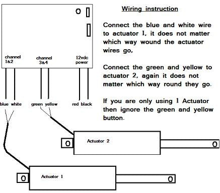
The FIRGELLI 4-channel receiver board is designed to control two linear actuators using four channels—two channels per actuator for bidirectional control (extend and retract). Each actuator requires a dedicated pair of channels to reverse polarity and change direction.
The standard wiring configuration connects as follows: Channel 1 and Channel 2 control the first actuator, while Channel 3 and Channel 4 control the second actuator. The receiver board features clearly labeled terminals for each channel output, along with power input terminals that accept 12V or 24V DC depending on your actuator specifications. When wiring multiple actuators, maintaining consistent polarity is essential—reversing the connections will cause the actuator to move in the opposite direction from the button press.
Connect your power supply to the main input terminals on the receiver board, ensuring the voltage matches your actuator requirements. Most FIRGELLI Premium and Classic series actuators operate on 12V DC, while some industrial models require 24V. The power supply must provide adequate current for both actuators operating simultaneously—calculate the combined amperage draw and add a 20% safety margin.
For applications requiring more than two actuators, you can parallel additional actuators to the existing channel outputs, provided the total current draw per channel remains below 5 amps. This allows configurations such as synchronized dual actuators on each channel pair, useful for applications like lift systems or large hatches requiring balanced force distribution.
Should you use momentary or sustaining mode?
The remote control system ships pre-configured in momentary mode, but can be easily switched to sustaining mode depending on your application requirements. Understanding these two operational modes is crucial for selecting the right configuration for your project.
Momentary Mode Operation
In momentary mode, the actuator moves only while the button is actively pressed. Releasing the button immediately stops actuator movement. This mode provides precise positional control and is ideal for applications where you need to stop at specific positions—such as adjustable shelving, camera sliders, or any situation where intermediate positioning is important. Momentary mode also offers a safety advantage by requiring continuous user engagement to maintain movement.
Sustaining Mode Operation
Sustaining mode, also called latching mode, requires only a single button press to initiate full travel. Once activated, the actuator continues moving until it reaches its mechanical end stop or until you press the button again to stop it. This mode is particularly useful for applications where full extension or retraction is the typical operation—such as TV lifts, pop-up platforms, or automated covers that are always either fully open or fully closed.
Switching Between Modes
To change from momentary to sustaining mode, you'll need to access the jumper configuration inside the receiver housing. Open the receiver case carefully—typically secured with small screws—to expose the circuit board. Locate the mode selection jumper, which connects two pins together in the default momentary configuration.

Remove the jumper completely for momentary mode, or reposition it to connect the sustaining mode pins as indicated on the board's silkscreen markings. After adjusting the jumper, you must power cycle the receiver—disconnect power completely, wait five seconds, then reconnect. This reset allows the microcontroller to read the new configuration and apply the appropriate mode.
Note that the mode setting applies to all channels simultaneously—you cannot configure some channels for momentary and others for sustaining operation on the same receiver. If your application requires mixed mode operation, consider using separate receiver boards for different actuator groups.
| Mode | Behavior | Best for |
|---|---|---|
| Momentary (default) | Motion only while button is held | Intermediate positioning, adjustable shelving, camera sliders, safety-critical stops |
| Sustaining (latching) | Single press runs to end stop or until next press | TV lifts, pop-up platforms, covers that are always fully open or closed |
How do you program additional remotes to the same receiver?
The system supports multiple remote transmitters paired to a single receiver, allowing different users or locations to control the same actuator system. This capability is valuable in workshop environments, accessibility applications, or anywhere multiple control points enhance usability.
Step-by-Step Programming Procedure
Programming additional remotes requires accessing the programming button on the receiver circuit board. Open the receiver case and locate the programming button—typically a small tactile switch near the antenna connection. The programming sequence follows a specific protocol to ensure reliable pairing:

Press and hold the programming button on the receiver board for approximately three to five seconds until the red LED begins flashing. This indicates the receiver has entered programming mode and is ready to accept new transmitter codes. While the LED is flashing, press any button on the first remote you want to program. You'll see the LED respond with a brief pattern change, confirming the remote has been registered.
Repeat this button press for each additional remote, pressing one button on each transmitter while the receiver remains in programming mode. If you're programming four remotes, you'll press a button on each of the four transmitters in sequence. The receiver can typically store up to eight individual remote transmitter codes, though this may vary by model.
Important Programming Notes
When adding new remotes to an existing system, you must reprogram all remotes you want to keep active—the programming process clears previous codes and registers only the remotes programmed in the current session. If you forget to reprogram an existing remote during the session, it will no longer communicate with the receiver.
After completing the programming sequence, remove power from the receiver board completely and then reconnect it. This power cycle finalizes the programming and ensures all remotes are properly synchronized with the receiver. Test each remote to verify all buttons function correctly before reassembling the housing.
When do you need external relays for high-current actuators?
The 4-channel receiver board is rated for a maximum of 5 amps per channel, making it compatible with most standard linear actuators including our Premium and Classic series. However, high-force applications often require industrial actuators that draw significantly more current—sometimes up to 20 amps during peak load conditions.
Connecting a high-current actuator directly to the control board will cause immediate and irreversible damage due to thermal overload of the board's switching transistors. The proper solution involves using external SPDT (Single Pole Double Throw) relays rated for 20 amps or higher to isolate the control signals from the high-current actuator circuit.
Relay-Based Isolation Circuit
For each actuator requiring high-current capacity, you'll need two SPDT relays—one for each direction of travel. The control board's channel outputs switch the relay coils, while the relay contacts handle the actual high-current switching to the actuator. This configuration protects the control electronics while providing full bidirectional control of heavy-duty actuators.
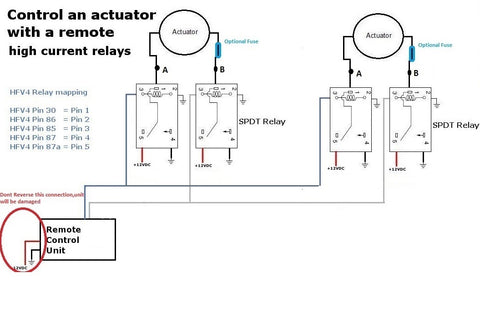
Wire the circuit as shown in the diagram above. The power supply connects directly to the common terminals of both relays, bypassing the control board for the high-current path. The control board's channel outputs connect to the relay coils through the relay's control terminals. When a button is pressed, the control board energizes the appropriate relay coil, which closes the contacts and completes the high-current circuit to the actuator.
Selecting Appropriate Relays
Choose automotive-grade SPDT relays rated for at least 20 amps continuous duty at 12V or 24V depending on your system voltage. The relay coil voltage must match your control voltage—typically 12V for most FIRGELLI systems. Look for relays with normally open (NO) and normally closed (NC) contacts to enable proper polarity reversal for bidirectional actuator control.
The relay configuration allows you to connect additional actuators in parallel at points A and B in the circuit diagram, provided the total current through each relay doesn't exceed its 20-amp rating. This enables synchronized operation of multiple high-force actuators from a single channel pair—useful in applications like large gates, heavy platforms, or commercial TV lift installations.
Using Wiring Harnesses for Clean Installation
FIRGELLI offers pre-made wiring harnesses that simplify the relay installation process. These harnesses feature color-coded wires, pre-crimped terminals, and appropriate wire gauges for high-current applications. Using a quality wiring harness reduces installation time, minimizes connection errors, and provides a more professional finished appearance compared to field-spliced connections.
What are the receiver's technical specifications and compatibility limits?
Understanding the technical capabilities and limitations of the 4-channel remote control system ensures reliable operation and prevents damage to components. The receiver board operates on 12V or 24V DC input, automatically adapting to the supplied voltage. The RF transmission operates in the 433MHz frequency band common to many consumer automation devices, providing reliable range of approximately 30-50 meters in open air, with reduced range through walls and obstacles.
Each channel is capable of switching up to 5 amps continuously at the system voltage. This current rating is conservative and includes thermal derating for continuous operation. Brief surge currents during actuator startup may exceed 5 amps momentarily without damage, but sustained overcurrent will damage the board's MOSFET switching transistors.
Compatible Actuator Models
The direct-connection configuration (without external relays) is compatible with most FIRGELLI standard force actuators, including Premium series actuators (typically drawing 2-4 amps), Classic series actuators (typically drawing 2-5 amps), and micro linear actuators (typically drawing 1-3 amps). These actuators offer force ratings from 50 to 400 pounds depending on the specific model, covering a wide range of automation applications.
For higher force requirements, heavy-duty and industrial actuators requiring 6-20 amps must be connected through external relay isolation as detailed in the previous section. Always verify the specific current draw of your actuator model under load—this information is available on the product specification sheet for each actuator.
| Actuator class | Typical current draw | Direct connect to 5 A receiver? | Relay isolation required? |
|---|---|---|---|
| Micro linear | 1–3 A | Yes | No |
| Premium series | 2–4 A | Yes | No |
| Classic series | 2–5 A | Yes (verify under load) | No |
| Heavy-duty / industrial | 6–20 A | No | Yes — 20 A SPDT, one pair per actuator |
Power Supply Requirements
Select a power supply that provides adequate current for simultaneous operation of both actuators plus a 20% safety margin. For example, two actuators each drawing 4 amps under load require a power supply rated for at least 9.6 amps (4A + 4A = 8A × 1.2 = 9.6A). Round up to the next standard rating—in this case, a 10-amp power supply would be appropriate.
Using an undersized power supply causes voltage sag under load, resulting in sluggish actuator performance, potential control glitches, and shortened actuator life due to operation below rated voltage. Quality switching power supplies designed for actuator applications provide stable voltage regulation even under varying loads.
Troubleshooting Common Issues
Most problems with remote control systems stem from incorrect wiring, inadequate power supply capacity, or programming errors. Systematic troubleshooting identifies and resolves issues quickly.
Remote Control Not Responding
If the remote transmitter doesn't control the actuators, first verify that the receiver board has power—most boards include a power indicator LED that should be illuminated when properly powered. Check that the antenna wire is properly connected and extended—coiling or shortening the antenna significantly reduces range. If the remote worked previously but stopped, the transmitter battery may be depleted—replace with a fresh battery of the correct type.
If multiple remotes were programmed and some work while others don't, the non-functioning remotes may have been excluded during the last programming session. Reprogram all remotes following the procedure outlined earlier, ensuring you register each remote during the same programming session.
Actuator Moves in Wrong Direction
If pressing the extend button retracts the actuator or vice versa, the actuator wiring polarity is reversed. Swap the two wires connecting to that actuator—either at the actuator end or at the receiver board terminals. This reverses the polarity and corrects the direction of travel. In a dual actuator system, each actuator's polarity is independent, so it's possible for one to be wired correctly while the other is reversed.
Actuator Stops Prematurely or Moves Sluggishly
Sluggish performance or unexpected stopping typically indicates inadequate power supply capacity or excessive voltage drop in the wiring. Measure the voltage at the actuator terminals while it's moving under load—voltage should remain within 10% of the nominal rating (10.8V minimum for a 12V system). If voltage drops below this threshold, either upgrade to a higher capacity power supply or reduce wiring resistance by using heavier gauge wire for long cable runs.
In relay-based high-current systems, verify that all relay contact connections are clean and tight. Corroded or loose connections create resistance that causes voltage drop and heating. Clean contacts with electrical contact cleaner and ensure all crimp connections are mechanically sound.
What advanced configurations does the 4-channel system support?
Beyond basic dual actuator control, the 4-channel system enables several advanced configurations that expand functionality for specialized applications.
Synchronized Actuator Pairs
For applications requiring perfectly synchronized movement of two actuators—such as balanced lift platforms or dual-sided gates—connect both actuators in parallel to the same channel pair. This ensures both actuators receive identical control signals simultaneously. When paralleling actuators, use identical models with matching specifications to ensure synchronized movement. Mixing different actuator models with varying speeds or force characteristics results in uneven movement and potential binding.
Feedback actuators with position sensing provide the most precise synchronization, as they enable closed-loop control that compensates for load variations or mechanical differences between actuators. For critical synchronization applications, consider using feedback actuators with an appropriate control box that supports position feedback.
Implementing External Limit Switches
While most linear actuators include internal limit switches that stop movement at full extension and retraction, some applications benefit from external limit switches that stop travel at intermediate positions. External switches can be wired in series with the actuator to interrupt power when the desired position is reached, regardless of whether the remote button is still pressed.
This configuration is particularly useful for applications with position requirements that differ from the actuator's full stroke length, or for safety limits that prevent over-travel in constrained installations. Use limit switches rated for the actuator's current draw and ensure proper normally-closed (NC) wiring to maintain circuit integrity until the switch is activated.
Integration with Arduino and Microcontrollers
For users comfortable with electronics and programming, the 4-channel receiver can be integrated with Arduino or other microcontroller systems by monitoring the channel output states. This enables automated sequences, position memory functions, or integration with sensors for responsive actuation based on environmental conditions. The channel outputs can trigger relay inputs on microcontroller boards, allowing the remote to serve as a manual override for automated systems.
What are the installation best practices and safety considerations?
Proper installation ensures reliable long-term operation and minimizes the risk of component failure or safety hazards. Always disconnect power before making any wiring connections or adjustments to prevent short circuits or shock hazards. Use wire gauges appropriate for the current draw—16 AWG wire is suitable for runs up to 10 feet with loads under 5 amps, while 14 AWG or heavier should be used for longer runs or higher currents.
Secure all wiring with appropriate strain relief to prevent mechanical stress at connection points. Protect exposed terminals and connections inside enclosures to prevent accidental shorts. When mounting the receiver board, ensure adequate ventilation—the switching transistors generate heat that must dissipate to prevent thermal damage. Avoid mounting the receiver in sealed enclosures unless provisions for heat dissipation are included.
Antenna Placement for Optimal Range
The receiver antenna should be extended to its full length and positioned away from metal surfaces that can shield or reflect RF signals. If the receiver is mounted inside a metal enclosure, route the antenna outside the enclosure through a non-conductive grommet. For installations with range issues, consider relocating the receiver to a more central position or using an antenna extension cable to position the antenna in a less obstructed location.
Mechanical Mounting and Load Considerations
Ensure actuators are properly mounted using appropriate mounting brackets that secure both the actuator body and rod end. Misalignment between mounting points causes side-loading that dramatically shortens actuator life and reduces force capacity. Use rod end bearings or clevis mounts that allow articulation to accommodate any misalignment in the mechanical system.
Never exceed the actuator's rated force capacity—overloading causes premature wear of internal components and may stall the motor, resulting in excessive current draw that can damage the control system. If your application requires more force, select a higher-rated actuator model rather than overloading a smaller unit.
How should you test the system before trusting it in service?
A control system that works once is not a control system that works. Before you bolt the receiver into its final enclosure or commit to a finished installation, run through the following sequence — it catches almost every wiring, power, and configuration error in under fifteen minutes.
- Power-on check. Confirm the receiver's power LED illuminates and stays steady. A flickering LED indicates marginal power supply capacity or a loose connection.
- Polarity verification (no load). With the actuator disconnected from its mechanical mount, jog each channel briefly. Extend should extend, retract should retract. If reversed, swap the two actuator leads at the receiver terminals.
- Range walk-test. With the receiver mounted in its final location and the antenna fully extended, walk to the furthest expected operating point and confirm reliable response. Test through any walls or panels in the signal path.
- Loaded voltage check. With the actuator under its real working load, measure DC voltage directly at the actuator terminals during motion. For a 12 V system, voltage should stay above 10.8 V. Anything lower indicates undersized supply or wire gauge.
- Cycle test. Run both actuators through full extend/retract cycles repeatedly under load — not just once. A one-time success proves the wiring; ten cycles under load prove the design.
- Mode-change verification. After switching the momentary/sustaining jumper, power-cycle the receiver and confirm the new mode behaves as expected on all four channels before final installation.
Where does a 4-channel dual-actuator remote system actually get used?
The combinations of two independent actuators, RF control through walls, and selectable momentary or latching behavior fit a broader range of installations than a single-channel switch ever could. Common deployment categories:
- Smart furniture: pop-up TV lifts, motorized cabinets, hidden compartments, adjustable workbenches and shelving.
- RV and camper van builds: bed lifts, slide-outs, cargo hatches, awning controls.
- Home and commercial access: motorized roof hatches, gates, attic stair lifts.
- Workshop and industrial: dual-actuator lift platforms, synchronized large-hatch systems, automated covers.
- Accessibility: multiple control-point installations where caregivers and users both need remote control of the same system.
- Entertainment and retail display: synchronized panel lifts, reveal mechanisms, pop-up signage.
What should you do next?
The FIRGELLI 4-channel remote control system provides a versatile, reliable solution for wireless control of dual linear actuator installations. By understanding the wiring configurations, operation modes, programming procedures, and appropriate use of external relays for high-current applications, you can design and implement robust automation systems for a wide range of applications.
Whether you're building adjustable furniture, custom access systems, or specialized machinery, proper configuration of your remote control system ensures smooth operation and long component life. Remember to match your power supply to the total system requirements, use appropriate wire gauges for your application, and implement relay isolation for any actuators drawing more than 5 amps per channel.
For additional support with your project, consult the extensive technical resources available on the FIRGELLI Automations website, or contact our technical support team for application-specific guidance. With proper planning and installation, your dual actuator remote control system will provide years of reliable wireless operation.
Frequently Asked Questions
How many actuators can I control with one 4-channel remote receiver?
The 4-channel receiver is designed to control two actuators independently, with each actuator using two channels for bidirectional control (extend and retract). However, you can connect additional actuators in parallel to existing channels if the total current draw per channel remains below 5 amps. For example, you could connect two identical actuators to the same channel pair for synchronized operation, provided their combined current draw doesn't exceed the 5-amp limit. If you need to control more than two actuators independently, you would need multiple receiver boards.
What is the range of the RF remote control and does it work through walls?
The 4-channel remote operates on 433MHz RF frequency and provides approximately 30-50 meters (100-165 feet) of range in open air with clear line of sight. Unlike infrared remotes, RF remotes do not require line of sight and will work through walls, doors, and other obstacles. However, range is reduced when operating through obstacles—expect 50-70% of the open-air range when transmitting through standard residential construction. Metal structures, concrete with rebar, and other dense materials cause more significant range reduction. The advantage of RF over infrared is that you can control actuators from another room or through cabinet doors without needing to point directly at the receiver.
Should I use momentary mode or sustaining mode for my application?
Choose momentary mode when you need precise control of actuator position and want to stop at intermediate points during travel. This mode is ideal for adjustable shelving, camera positioning systems, or any application where you frequently stop between fully extended and fully retracted positions. Choose sustaining mode for applications where the actuator typically runs to full extension or retraction, such as TV lifts, pop-up mechanisms, or automated covers. Sustaining mode is more convenient for these applications because it requires only a single button press rather than holding the button during the entire travel. Consider the safety implications as well—momentary mode provides better control in situations where you may need to stop quickly in response to obstacles or changing conditions.
When do I need to use external relays with my actuator setup?
You must use external SPDT relays rated for 20 amps when your actuators draw more than 5 amps per channel. This includes most heavy-duty and industrial actuators designed for high-force applications. Check your actuator's specification sheet for peak current draw—if it lists a value above 5 amps, you need relay isolation to protect the control board. Even if your actuator is rated below 5 amps no-load, consider relay isolation if it will operate under heavy loads that significantly increase current draw. The cost of a few relays is minimal compared to replacing a damaged control board, and relay isolation provides additional switching capacity for future expansion or higher-force actuator upgrades.
Can I program multiple remotes to work with the same receiver?
Yes, the receiver can be programmed to recognize up to eight separate remote transmitters, allowing multiple users or control locations for the same actuator system. This is useful in workshop settings, accessibility applications, or anywhere you want control points at different locations. To program multiple remotes, you must follow the complete programming sequence and register all remotes—including previously programmed ones—in the same programming session. The system clears all previous remote codes when you enter programming mode, so any remote not included in the current session will stop working. After programming, all registered remotes will have full control over all four channels on the receiver.
How do I determine what size power supply I need for my dual actuator system?
Calculate the power supply requirement by adding the maximum current draw of both actuators and adding a 20% safety margin. Find each actuator's current draw specification on its product page or datasheet—this is typically listed as the stall current or maximum current. For example, if each actuator draws 4 amps under load, your calculation would be: 4A + 4A = 8A total, then 8A × 1.2 = 9.6A with safety margin. Round up to the next standard power supply rating—in this case, a 10-amp power supply would be appropriate. Using an undersized power supply causes voltage drop under load, resulting in poor actuator performance and potential control issues. Voltage (12V or 24V) must match your actuator specifications exactly—mixing voltages will damage actuators or result in dramatically reduced performance.
Why does my actuator move in the wrong direction when I press a button?
If the actuator extends when you press the retract button (or vice versa), the actuator wiring polarity is reversed at the connection point. This is easily corrected by swapping the two wires that connect to that actuator—you can swap them either at the actuator terminals or at the receiver board connection points, whichever is more convenient. In a dual actuator system, each actuator's polarity is independent, so one actuator may be wired correctly while the other is reversed. After swapping the wires, test the operation to confirm the direction is now correct. This is not a defect—it's simply a matter of establishing the correct polarity relationship between the control signal and the actuator motor direction.
About the Author
This article was written by Robbie Dickson, Founder and Chief Engineer of FIRGELLI Automations. Robbie has spent his career in motion engineering — including time at Rolls-Royce, BMW, Isuzu, and Ford — before founding FIRGELLI in 2002 to focus on linear motion design and actuator systems. Read more on Wikipedia.


