Before you start cutting glass or fixing components in place, you need to know exactly where your mirror system will form its image. Getting the object distance, focal length, or image distance wrong doesn’t just blur a telescope—it ruins your results in solar concentrators, laser focus optics, or automotive mirrors. The calculator below solves for whichever mirror parameter you’re missing, using any two others. These relationships turn up all the time in telescopes, solar setups, lasers, car mirrors, and vision systems. This page lays out the formulas, sign conventions, an example calculation, and the theory in a way you can actually use.
What is the Mirror Equation?
The mirror equation links how far your object is from the mirror, the mirror's focal length, and where the resulting image shows up. If you know any two, you can calculate the third—no guesswork needed.
Simple Explanation
Picture a curved mirror as a surface that redirects light rays in a predictable way—just a simple bending of paths, not magic. The mirror equation lets you figure out, using the actual distances or curvatures, where the image lands. If you know two pieces—object distance and focal length, for example—it spits out the third directly.
📐 Browse all 1000+ Interactive Calculators
How to Use This Calculator
- Pick what you want to solve for—image distance, object distance, focal length, magnification, image height, or radius of curvature—using the dropdown.
- Plug in the necessary values. Depending on mode, you’ll enter things like object distance, image distance, focal length, or object height. Stick to centimeters and keep the sign rules in mind.
- Double-check your signs: concave mirrors need negative focal length, convex mirrors positive; real image distances are positive, virtual are negative.
- Click Calculate and get your result.
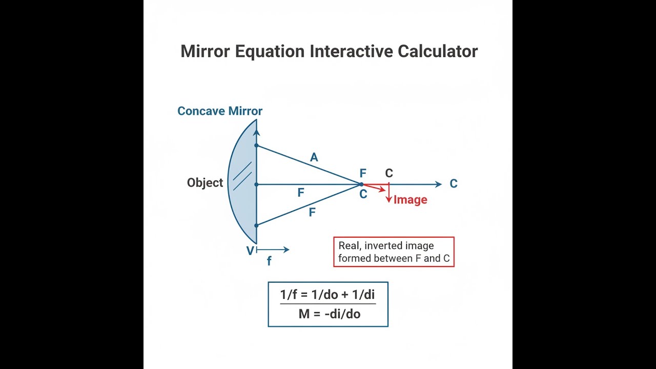
Mirror Geometry Diagram

Interactive Mirror Equation Calculator
This calculator is intended for education, concept evaluation, and preliminary design. Results are based on the equations and assumptions described on this page, but cannot account for every real-world load case, tolerance, material property, environmental condition, installation detail, safety factor, code, or regulatory requirement. Verify all inputs, assumptions, units, and results independently before selecting components or using the result in a real application. Safety-critical, structural, medical, lifting, transportation, or regulated applications must be reviewed by a qualified engineer.
Mirror Equation Interactive Visualizer
This visualizer lets you see for yourself how varying object distance, focal length, and curvature changes where images form. Adjust the settings and you'll spot why engineering disciplines like automotive mirrors or solar concentrators depend on practical knowledge of these relationships.
IMAGE DISTANCE
60.0 cm
MAGNIFICATION
-1.0×
IMAGE HEIGHT
-15.0 cm
FIRGELLI Automations — Interactive Engineering Calculators
Mirror Equation Formulas
Primary Mirror Equation
This equation links image distance, object distance, and focal length—pick any two, solve for the third.
1/f = 1/do + 1/di
Where:
- f = Focal length (cm, m) — distance from vertex to focal point
- do = Object distance (cm, m) — distance from object to mirror vertex
- di = Image distance (cm, m) — distance from image to mirror vertex
Magnification Equation
This tells you how much bigger (or smaller) the image is compared to the object—and if it’s upright or inverted.
m = -di/do = hi/ho
Where:
- m = Magnification (dimensionless) — ratio of image size to object size
- hi = Image height (cm, m)
- ho = Object height (cm, m)
Focal Length and Radius Relationship
Radius of curvature is just twice the focal length—use this if you have one, but need the other.
f = R/2
Where:
- R = Radius of curvature (cm, m) — radius of the spherical surface
Sign Conventions
- Focal length: Use negative for concave mirrors (converging), positive for convex mirrors (diverging)
- Object distance: Positive for real objects on reflective side
- Image distance: Positive for real images (same side as object), negative for virtual images (behind mirror)
- Heights: Positive above principal axis, negative below
- Magnification: Negative means image is inverted, positive means upright
Simple Example
Let’s say you have a concave mirror with a 20 cm focal length and you place an object 30 cm in front of it:
- Object distance (do) = 30 cm
- Focal length (f) = −20 cm (concave, so negative)
- Image distance: 1/di = 1/f − 1/do = 1/(−20) − 1/30 → di = −60 cm
- Result: You get a virtual image 60 cm behind the mirror, magnified 2× and upright (magnification = +2)
Theory & Practical Applications of Mirror Equations
The mirror equation is practical geometry for light, as long as you stick to rays that stay close to the centerline (the optical axis). It’s not a ray-tracing software replacement, but when you need quick checks for where a mirror forms an image—or how big that image will be—this is the go-to tool. You’ll save time tweaking rough designs, especially in tasks like picking primary/secondary positions in telescopes or aligning solar dishes.
Derivation and Physical Basis
The mirror equation isn’t magic; you get it by following what happens to rays as they bounce off a spherical surface, using nothing but triangle geometry and the small-angle approximation (paraxial). For a spherical mirror with radius R, all rays parallel to the axis meet at f = R/2 after reflection. If you start with these triangles (one for the object, one for the image), the sign conventions come from the actual paths the rays follow. This shortcut only holds if your angles are small—take a wide mirror, and you’ll notice real rays miss this predicted focus.
There’s a trap here worth mentioning: as your object sneaks up on the focal point, do → f, the math spits out di approaching infinity. Practically, this means your reflected rays become parallel, never meet, and your image is theoretically “at infinity.” This is how you make a flashlight beam parallel or collimate a laser system. But in real builds, stray aberrations and finite-size effects mean you don’t get a sharp focus at infinite range; the approximation is only good if your aperture is not too big.
Sign Convention and Physical Interpretation
The negative sign in m = -di/do isn’t just a math quirk. With concave mirrors (real images), both distances are positive, so the image ends up inverted—just as expected from a real ray diagram. If your object gets inside the focal length, the image distance goes negative and the equation tells you the image is virtual and upright. These are the same principles behind makeup mirrors or dental optics. Convex mirrors (used for wide-view car mirrors) always give you negative image distances—meaning the image is virtual, always upright, but smaller than the real thing. You can use the exact same mirror formula for either type; just keep your signs straight and you’ll get sensible results.
Spherical Aberration and Validity Limits
The mirror equation holds up only if most rays stay close to the center—once you use a wide optical aperture, you quickly run into spherical aberration. That means off-axis rays don’t focus where the formula says. Spherical aberration for a mirror with radius R and aperture D roughly scales with D⁴/(128R³f). In plain English: make the mirror too wide relative to its curvature, and your focus gets fuzzy. That’s why telescopes aiming for sharp images often use parabolic instead of spherical mirrors, unless they keep the focal ratio high, generally above f/3 for anything serious.
If you’re building a solar concentrator, controlling costs often means accepting some aberration. For precision optics (telescope mirrors, for example), designers either restrict their aperture or move to parabolic shapes once D/R gets above about 0.15—otherwise image quality tanks fast.
Industrial Applications Across Sectors
The mirror formula turns up way outside visible light. Antenna dishes for satellites use the same principles; it doesn’t matter if the “rays” are at radio or optical frequencies. In those setups, the exact feed location at the focal point maximizes performance, and thermal expansion can cause enough drift to require ongoing tweaks. Sun-concentration setups get even trickier: with a huge mirror, you have to watch for angular size of the sun itself, mirror slope errors, and even wind or temperature effects flattening out fine focus. That’s why nobody does precise solar furnace design with just the basic mirror formula alone—it gets you close, but not right on.
In laser cutters or other high-power systems, keeping the focus in the right spot is a constant battle. Even a slight shift in mirror temperature (and that happens fast at these power levels) moves your focus enough to matter. Good practice involves water cooling, keeping temperatures steady, and building in enough tolerance so thermal drift doesn’t ruin the cut.
Multi-Mirror Systems and Optical Path Analysis
If you’re lining up multiple mirrors, run the mirror equation on each reflection step by step. For Cassegrain telescopes, for example, the first (concave) mirror forms a real image, but that image acts as a “virtual object” for the next (convex) mirror. Combined system focal length is worked out from a formula involving both mirrors’ focal lengths and their separation, but you always come back to running the single-mirror equation for each element. The math gets a bit untidy if you’re also dealing with moving elements or large angular fields, so for those jobs, a full ray trace or simulation is much safer than purely relying on the algebra.
For beam steering with galvanometer mirrors—like in laser engraving heads—position-dependent focus errors crop up as you scan. If tolerances are tight, you need to account for this by hardware design or add real-time corrections. For most field sizes, the mirror equation gets you a baseline, but you’ll be off if you ignore beam path tilting.
Worked Example: Astronomical Telescope Primary Mirror Design
Suppose you want to design a Newtonian telescope with a 250 mm mirror and keep the tube reasonably short. Going for an f/6 ratio, the focal length is just 250 mm × 6 = 1500 mm. This gives a radius of curvature of 3 meters. To know whether Mars will show a sharp image, you run through: (1) actual focal length from design; (2) image size on the focal plane, using the small-angle formula; (3) check against spherical aberration, using the D⁴/(128R³) estimate; (4) compare aberration to diffraction, and (5) see if the resolving power matches the expected object (like Mars). Here, the aberration isn’t negligible, but for amateur observing, “good enough” can be just fine, especially since atmospheric conditions usually limit you anyway on Earth.
Thermal Effects in Precision Mirror Systems
With high-power laser mirrors, even small power absorption yields measurable thermal expansion. Focal shift can be a few millimeters on short-focal-length mirrors if you’re not careful with cooling. For aerospace, dropping the air pressure from ground to space lets mirrors “breathe” and change shape, which will move your focus unless you design for it with slots or compensated supports. Just a few micrometers of deflection is enough to lose performance if your tolerances are tight.
When your project gets more advanced (aspheric mirrors, adaptive optics), the basics behind the mirror equation still crop up, but you’ll want to model full ray paths or use dedicated tools. For other optical calculation needs—lenses, fiber, or diffractive elements—the engineering calculator library covers more ground.
Frequently Asked Questions
Free Engineering Calculators
Explore our complete library of free engineering and physics calculators.
Browse All Calculators →🔗 Explore More Free Engineering Calculators
About the Author
Robbie Dickson — Chief Engineer & Founder, FIRGELLI Automations
Robbie Dickson brings over two decades of engineering expertise to FIRGELLI Automations. With a distinguished career at Rolls-Royce, BMW, and Ford, he has deep expertise in mechanical systems, actuator technology, and precision engineering.
Video Walkthrough - How to Use This Calculator
Need to implement these calculations?
Explore the precision-engineered motion control solutions used by top engineers.


