Designing optical components for laser cavities, polarizing filters, or anti-reflection coatings requires knowing the exact angle at which p-polarized light passes through a dielectric interface with zero reflection — that's the Brewster angle, and getting it wrong costs you efficiency, polarization purity, or both. Use this Brewster Angle Calculator to calculate the Brewster angle, refractive indices, critical angle, refraction angle, or Fresnel reflectance using your material's refractive indices and incident angle. It matters across laser optics, optical coating design, and photographic polarizer engineering. This page includes the governing formula, a full worked example, underlying theory, and an FAQ.
What is Brewster's Angle?
Brewster's angle is the specific angle of incidence at which p-polarized light (light whose electric field oscillates in the plane of incidence) passes through a transparent surface with zero reflection. At any other angle, some light reflects back.
Simple Explanation
Think of light hitting a glass window at a shallow angle — you get a lot of glare. But tilt the glass to just the right angle, and that glare from one polarization direction disappears entirely. That exact angle is the Brewster angle. It's why polarized sunglasses cut reflections off water: they block the polarization that reflects most at those viewing angles.
📐 Browse all 1000+ Interactive Calculators
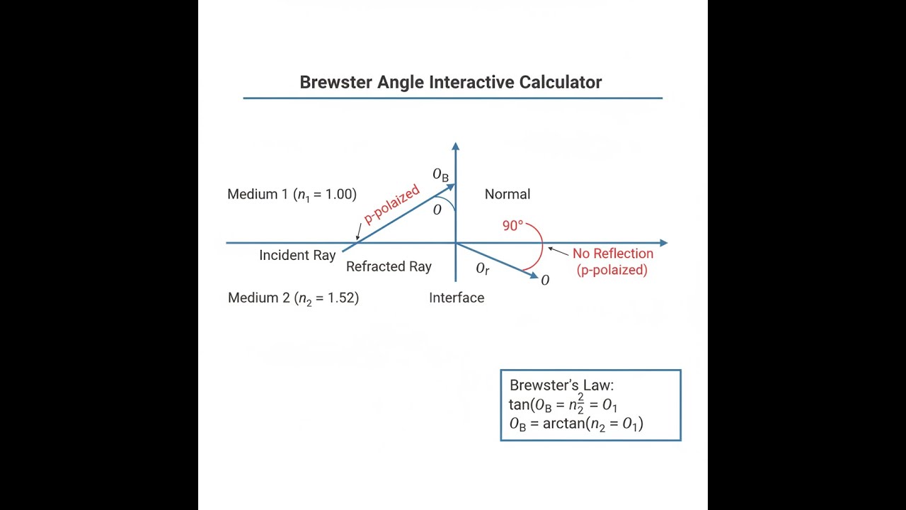
Brewster Angle Diagram

How to Use This Calculator
- Select your calculation mode from the dropdown — choose what you want to find (Brewster angle, refractive index, critical angle, reflectance, or refraction angle).
- Enter the refractive index of your incident medium (n₁) — air is 1.000, water is approximately 1.33, and common glass is around 1.50–1.52.
- Enter the refractive index of your transmission medium (n₂), or enter the known Brewster angle if you're solving for an index.
- Click Calculate to see your result.
Brewster Angle Interactive Calculator
Brewster Angle Interactive Visualizer
Watch how the Brewster angle eliminates p-polarized reflection while maintaining s-polarized reflection. Adjust refractive indices to see the angle change and visualize the perpendicular relationship between refracted and reflected rays.
BREWSTER ANGLE
56.3°
REFRACTION ANGLE
33.7°
P-REFLECT
0.0%
FIRGELLI Automations — Interactive Engineering Calculators
Governing Equations
Use the formula below to calculate the Brewster angle from two refractive indices.
Brewster Angle (Primary Equation)
θB = arctan(n2 / n1)
Where:
- θB = Brewster angle (degrees or radians)
- n1 = Refractive index of incident medium (dimensionless)
- n2 = Refractive index of transmission medium (dimensionless)
Refraction Angle at Brewster Incidence
θr = arctan(n1 / n2)
θB + θr = 90°
At Brewster angle, the refracted and reflected rays are perpendicular.
Fresnel Reflectance Coefficients
For s-polarization (perpendicular):
Rs = [(n1cos θi - n2cos θt) / (n1cos θi + n2cos θt)]²
For p-polarization (parallel):
Rp = [(n2cos θi - n1cos θt) / (n2cos θi + n1cos θt)]²
At θi = θB, Rp = 0
Critical Angle (for n1 > n2)
θc = arcsin(n2 / n1)
Total internal reflection occurs when θi ≥ θc
Simple Example
Light travels from air (n₁ = 1.0) into standard glass (n₂ = 1.5).
θ_B = arctan(1.5 / 1.0) = arctan(1.5) = 56.31°
Refraction angle = 90° − 56.31° = 33.69°
At this angle, p-polarized reflection = 0%. S-polarized reflection remains non-zero.
Theory & Practical Applications
Fundamental Physics of Brewster's Angle
Brewster's angle represents a unique optical phenomenon where p-polarized light (electric field oscillating parallel to the plane of incidence) experiences zero reflection at a dielectric interface. This occurs because at this specific angle, the refracted ray and the reflected ray would be perpendicular to each other. Since electromagnetic radiation cannot be emitted in the direction of the oscillating dipole (a fundamental consequence of Maxwell's equations), the reflected component vanishes entirely for p-polarization.
The physical mechanism involves the oscillating electric field in the transmission medium. When light refracts at the Brewster angle, the electrons in medium 2 oscillate along the direction that would generate the reflected ray. However, dipole radiation has zero intensity along the dipole axis itself—this is why radio antennas have nulls at their ends. At exactly θB = arctan(n₂/n₁), the geometry aligns such that the "would-be" reflected ray direction coincides with this radiation null, eliminating p-polarized reflection.
An important but often overlooked detail: Brewster's angle only eliminates reflection for p-polarized light. S-polarized light (electric field perpendicular to the plane of incidence) still experiences reflection at the Brewster angle, though the reflectance is typically small. The reflectance for s-polarization at the Brewster angle is given by Rs = [(n₂² - n₁²) / (n₂² + n₁²)]². For an air-glass interface (n₁ = 1.00, n₂ = 1.52), this yields approximately 7.3% reflectance for s-polarized light even at the Brewster angle.
Relationship to Snell's Law and Critical Angle
Brewster's angle and the critical angle represent fundamentally different optical phenomena, yet both emerge from the same underlying physics. Snell's law, n₁sin θi = n₂sin θt, governs all refraction. The Brewster condition imposes the additional constraint that θi + θt = 90°. Substituting this into Snell's law and using the identity sin(90° - θ) = cos(θ) yields the Brewster equation directly: tan θB = n₂/n₁.
The critical angle, conversely, represents the maximum refraction angle (θt = 90°) before total internal reflection occurs. This requires n₁ > n₂, and gives θc = arcsin(n₂/n₁). For standard air-to-glass incidence (n₁ < n₂), no critical angle exists in this direction. However, for glass-to-air transmission (n₁ = 1.52, n₂ = 1.00), the critical angle is 41.1° while the Brewster angle is 33.3°. At angles between Brewster and critical, partial p-polarization occurs with reduced but non-zero reflection. Beyond the critical angle, even p-polarized light experiences 100% reflection.
Industrial Applications in Optical Engineering
Laser Systems and Optical Isolators: High-power laser cavities use Brewster windows—optical elements oriented at the Brewster angle—to introduce intracavity elements with zero insertion loss for p-polarized light. This eliminates reflection-induced optical feedback that would destabilize the laser. A Nd:YAG laser cavity operating at 1064 nm with fused silica Brewster windows (n = 1.4496 at this wavelength) requires a window angle of 55.38° from normal. The intrinsic p-polarization selection means the laser output is naturally linearly polarized without requiring additional polarizing elements that would introduce loss.
Polarizing Beamsplitters: Brewster-angle "pile of plates" polarizers consist of multiple glass plates stacked at the Brewster angle. Each interface transmits p-polarized light with near-zero loss while reflecting a fraction of s-polarized light. A stack of 10 plates with per-interface s-reflectance of 7.3% yields total s-reflectance of 1 - (0.927)¹⁰ ≈ 52%, creating a moderately efficient polarizing beamsplitter. High-performance versions using 40-60 plates achieve extinction ratios exceeding 10,000:1 for applications in spectroscopy and interferometry.
Photography and Glare Reduction: Reflections from water, glass, and other dielectrics are predominantly p-polarized when viewed at angles near the Brewster angle. For water (n ≈ 1.33), the Brewster angle is 53.1°. Polarizing filters oriented to block p-polarized light dramatically reduce glare when photographing lakes, windows, or wet surfaces viewed at these angles. However, the effectiveness drops sharply at angles far from Brewster—shooting at 30° or 75° from normal shows minimal polarization in the reflected light.
Thin Film Coatings and Anti-Reflection Design: While anti-reflection (AR) coatings typically use quarter-wave optical thickness designs, Brewster angle physics influences the design of oblique-incidence AR coatings. For optical components used at non-normal incidence, achieving low reflection requires accounting for the polarization-dependent Fresnel coefficients. A coating optimized for normal incidence (0° angle of incidence) may show high p-polarized reflectance at 45° where Brewster effects dominate the optical response.
Worked Example: Optical Window Design for Laser System
Problem: You are designing a vacuum chamber window for a Ti:Sapphire laser system operating at 800 nm wavelength. The window must introduce minimal loss for the p-polarized laser beam. The vacuum chamber interior is at n₁ = 1.000 (vacuum), and you are considering fused silica windows with n₂ = 1.4533 at 800 nm. Calculate: (a) the required Brewster angle for the window orientation, (b) the refraction angle inside the window material, (c) the window thickness needed if the beam must travel 25.0 mm through the material path, and (d) the s-polarized reflectance at this angle.
Solution:
Part (a): Brewster Angle Calculation
θB = arctan(n₂ / n₁) = arctan(1.4533 / 1.000) = arctan(1.4533)
θB = 55.484°
The window must be oriented at 55.484° from the surface normal (34.516° from the window surface plane).
Part (b): Refraction Angle
At Brewster incidence, the refraction angle is complementary:
θr = 90° - θB = 90° - 55.484° = 34.516°
We can verify using Snell's law:
n₁ sin θB = n₂ sin θr
1.000 × sin(55.484°) = 1.4533 × sin(34.516°)
0.8238 = 1.4533 × 0.5669
0.8238 ≈ 0.8238 ✓
Part (c): Required Window Thickness
The beam travels at angle θr = 34.516° from normal through the material. If the path length through the material must be 25.0 mm:
Path length = thickness / cos(θr)
25.0 mm = t / cos(34.516°)
t = 25.0 mm × cos(34.516°) = 25.0 mm × 0.8238 = 20.60 mm
A window thickness of 20.60 mm provides the required 25.0 mm material path length.
Part (d): S-Polarized Reflectance
For s-polarization at Brewster angle:
Rs = [(n₁ cos θi - n₂ cos θt) / (n₁ cos θi + n— cos θt)]²
First, calculate the cosines:
cos θB = cos(55.484°) = 0.5669
cos θr = cos(34.516°) = 0.8238
Numerator: 1.000 × 0.5669 - 1.4533 × 0.8238 = 0.5669 - 1.1971 = -0.6302
Denominator: 1.000 × 0.5669 + 1.4533 × 0.8238 = 0.5669 + 1.1971 = 1.7640
Rs = (-0.6302 / 1.7640)² = (-0.3573)² = 0.1277 = 12.77%
Result: At the Brewster angle of 55.484°, p-polarized light experiences 0% reflection (ideal transmission), while s-polarized light still reflects 12.77%. For a two-surface window, the total s-loss would be approximately 24%, assuming the exit surface is also at Brewster angle. This demonstrates why Brewster windows provide intrinsic polarization selection, making them ideal for laser cavities where only one polarization state is desired.
Temperature and Wavelength Dependencies
Refractive indices are temperature- and wavelength-dependent, which means the Brewster angle shifts with these parameters. For fused silica, dn/dT ≈ 1.0 × 10⁻⁵ K⁻¹ at visible wavelengths. A 50 K temperature increase changes n from 1.4580 to 1.4585, shifting the Brewster angle from 55.55° to 55.59°—a small but measurable 0.04° change. In precision optical systems operating over wide temperature ranges, this necessitates either active angular control or acceptance of slightly degraded polarization performance at temperature extremes.
Chromatic dispersion creates wavelength-dependent Brewster angles. For crown glass (nF = 1.534 at 486 nm, nC = 1.520 at 656 nm), the Brewster angle shifts from 56.89° at blue wavelengths to 56.67° at red wavelengths—a 0.22° spread. Broadband laser systems or white-light polarizers must compromise on optimal angle selection or use wavelength-specific stages.
Limitations and Practical Considerations
Real optical surfaces deviate from the ideal planar interface assumed in Brewster angle calculations. Surface roughness on the scale of the wavelength introduces diffuse scattering that partially depolarizes reflected light, reducing the effectiveness of Brewster angle polarization. High-quality optical surfaces with RMS roughness below λ/10 (typically 50-80 nm for visible light) are necessary to maintain polarization purity. Additionally, contamination layers—even molecularly thin films—alter the effective refractive index at the interface, shifting the true Brewster angle by tenths of a degree.
Multi-layer dielectric structures complicate Brewster angle behavior. An air-coating-substrate system has two interfaces, each with its own Brewster angle. Perfect p-polarization transmission through such a structure requires simultaneous satisfaction of Brewster conditions at both interfaces, which is generally impossible unless the coating refractive index equals the geometric mean of air and substrate indices. This is why anti-reflection coatings for Brewster windows typically use graded-index designs rather than simple quarter-wave stacks.
Frequently Asked Questions
Free Engineering Calculators
Explore our complete library of free engineering and physics calculators.
Browse All Calculators →🔗 Explore More Free Engineering Calculators
About the Author
Robbie Dickson — Chief Engineer & Founder, FIRGELLI Automations
Robbie Dickson brings over two decades of engineering expertise to FIRGELLI Automations. With a distinguished career at Rolls-Royce, BMW, and Ford, he has deep expertise in mechanical systems, actuator technology, and precision engineering.
Need to implement these calculations?
Explore the precision-engineered motion control solutions used by top engineers.


