Description
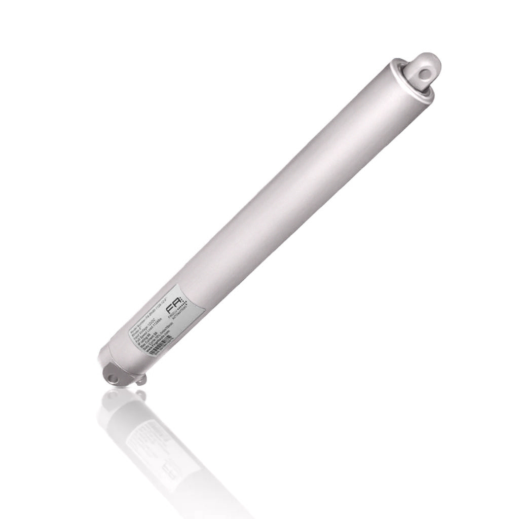
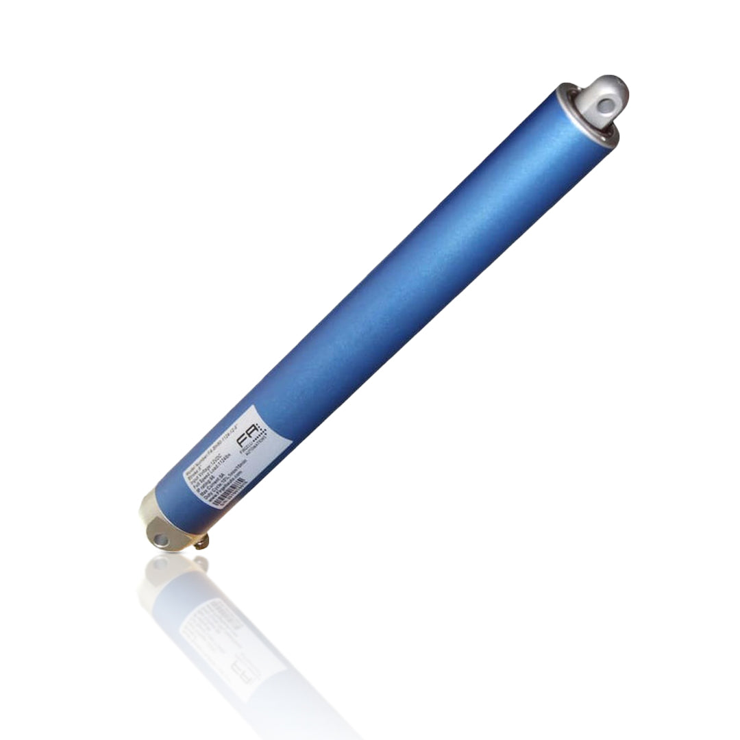
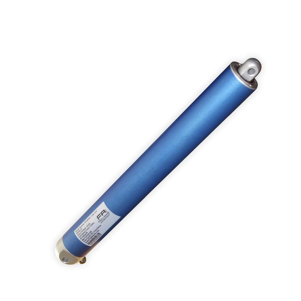
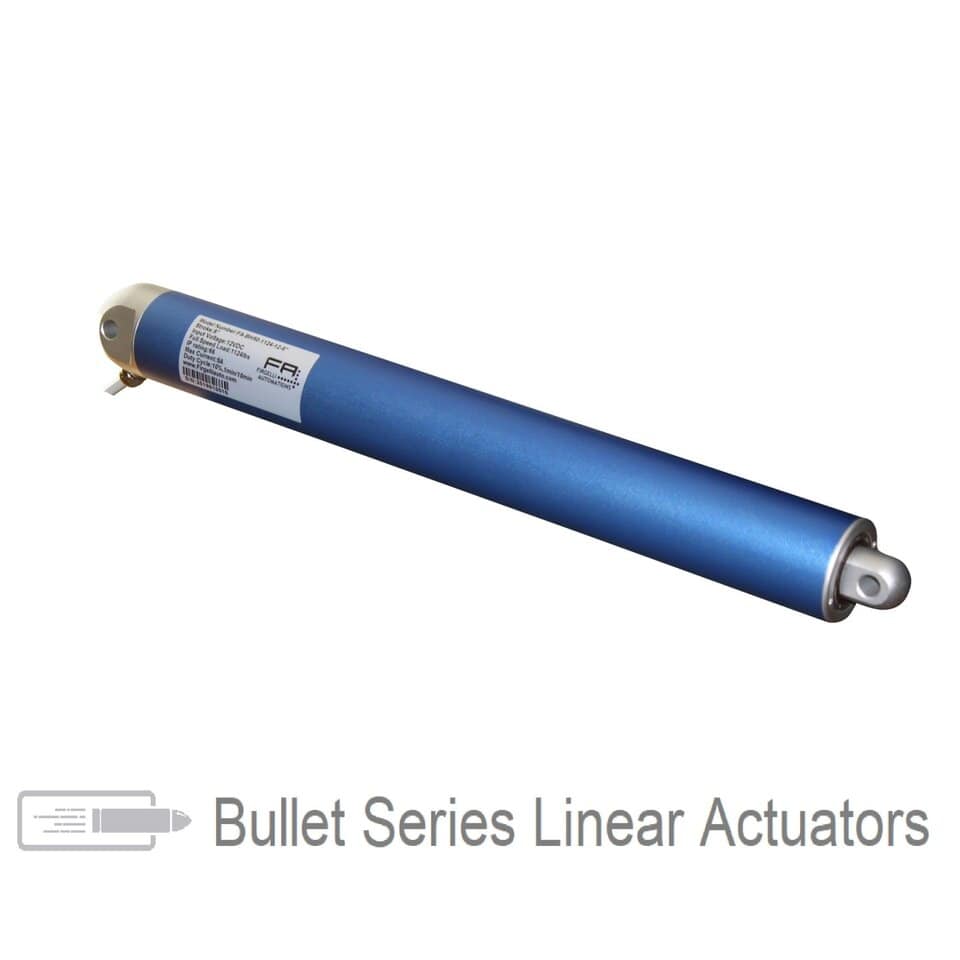
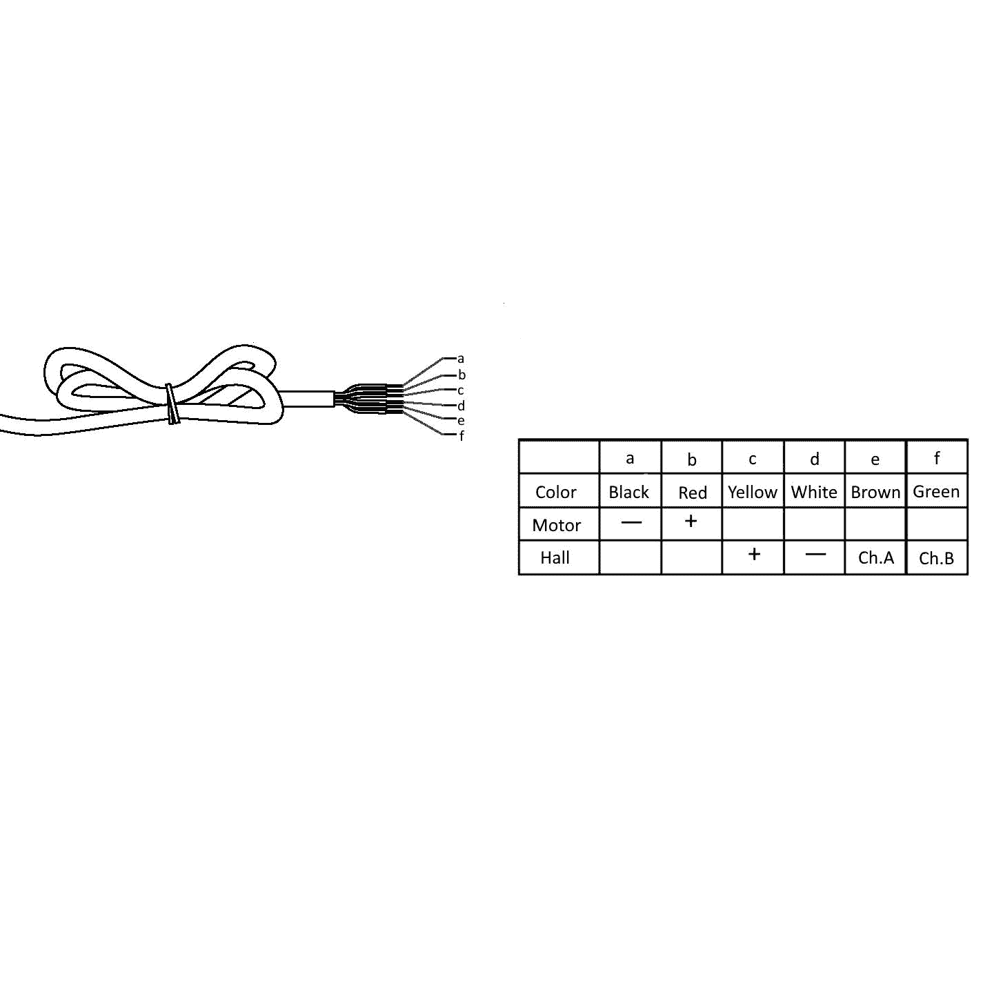
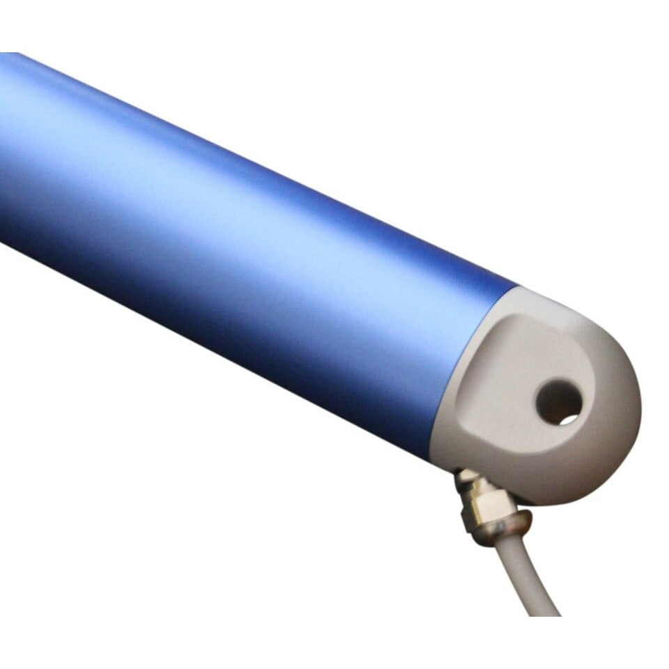
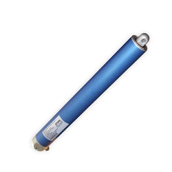
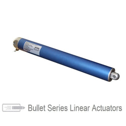
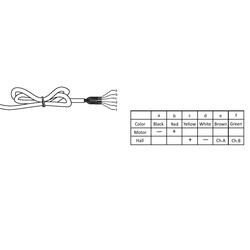
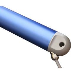
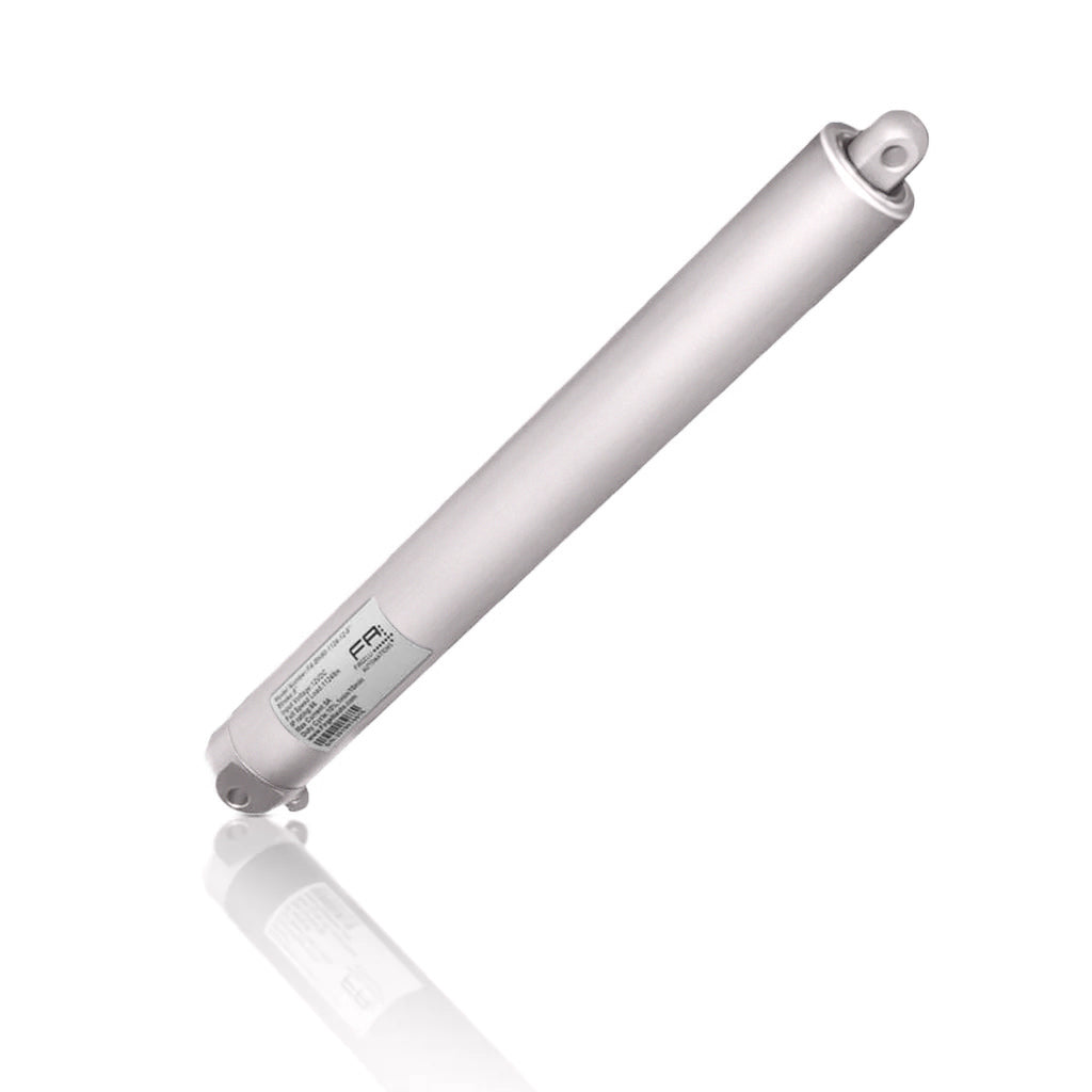
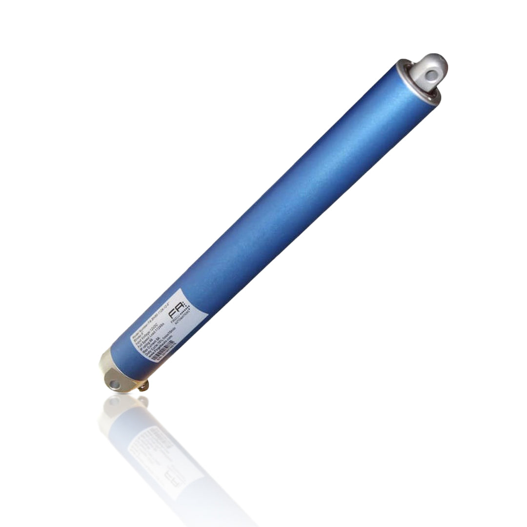
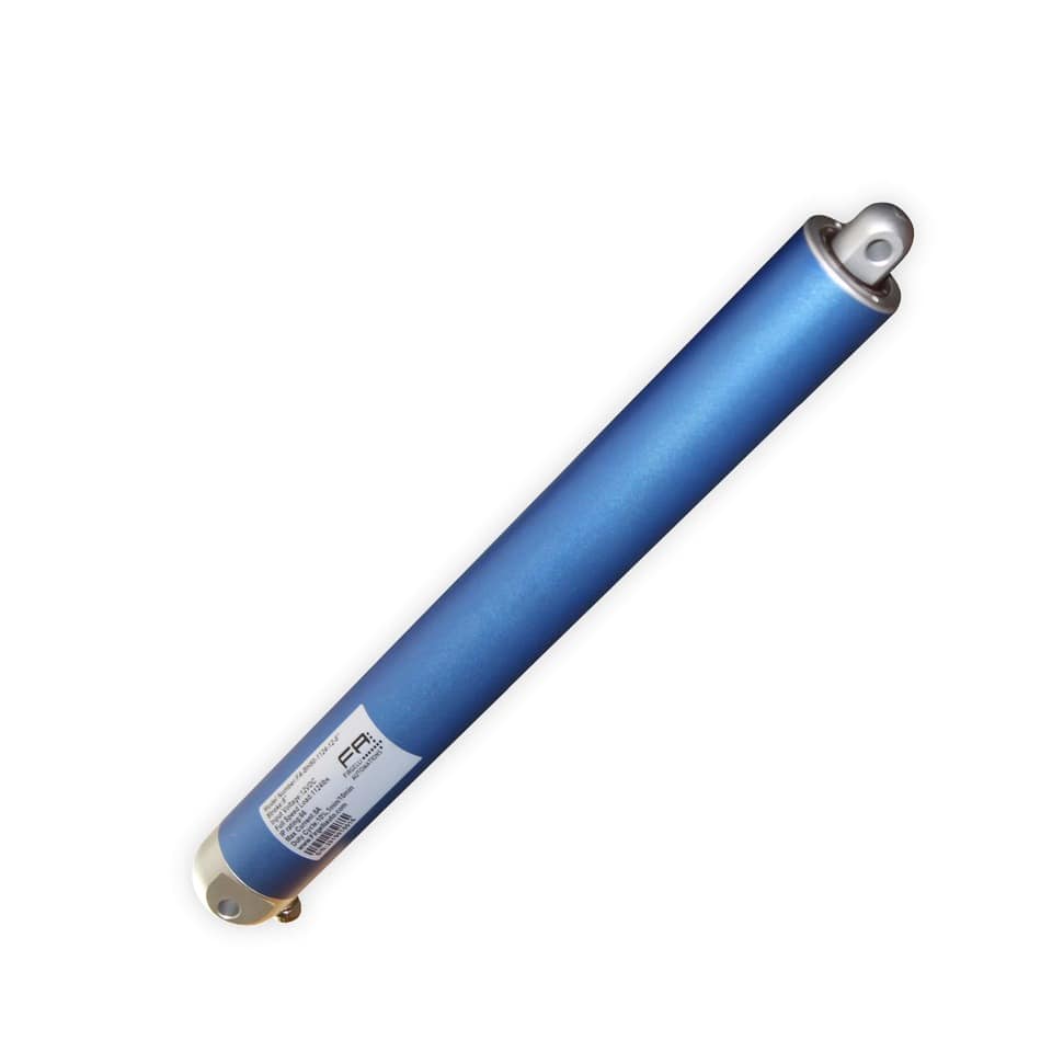
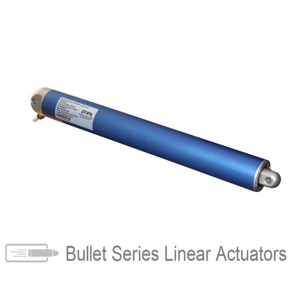
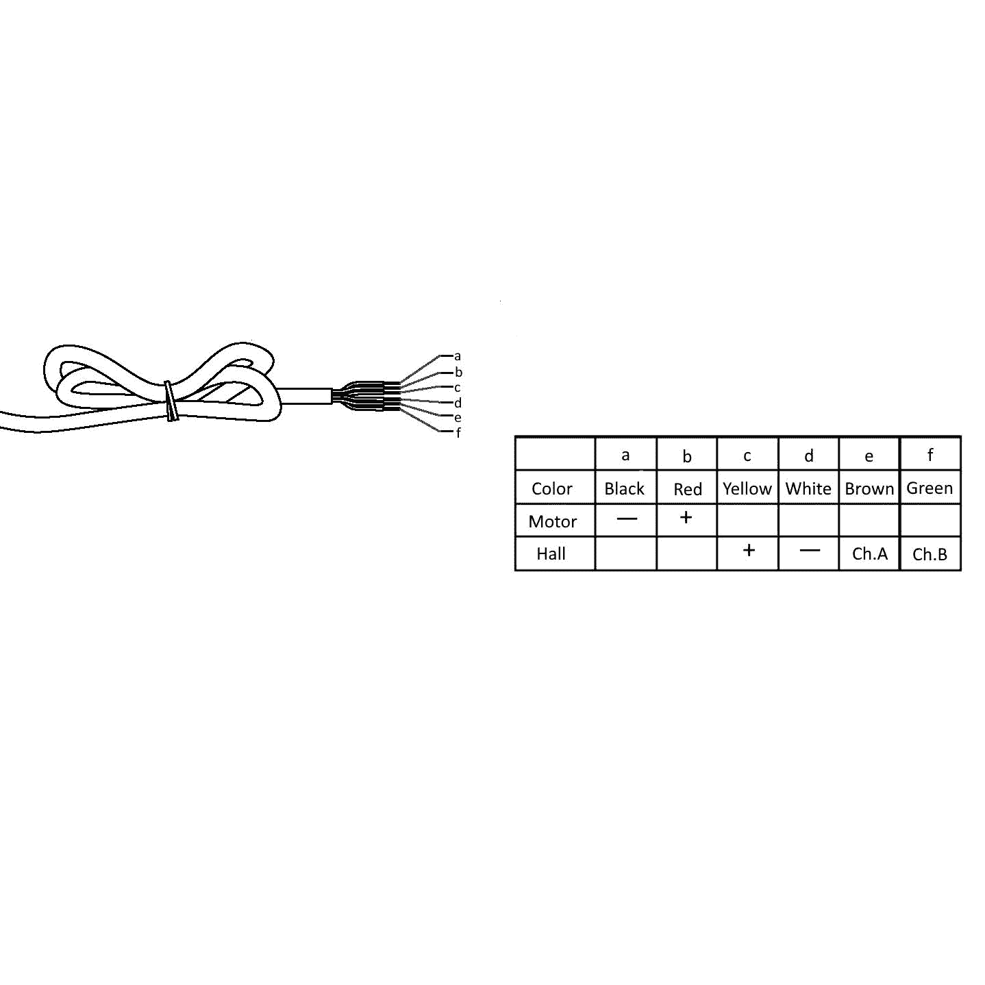
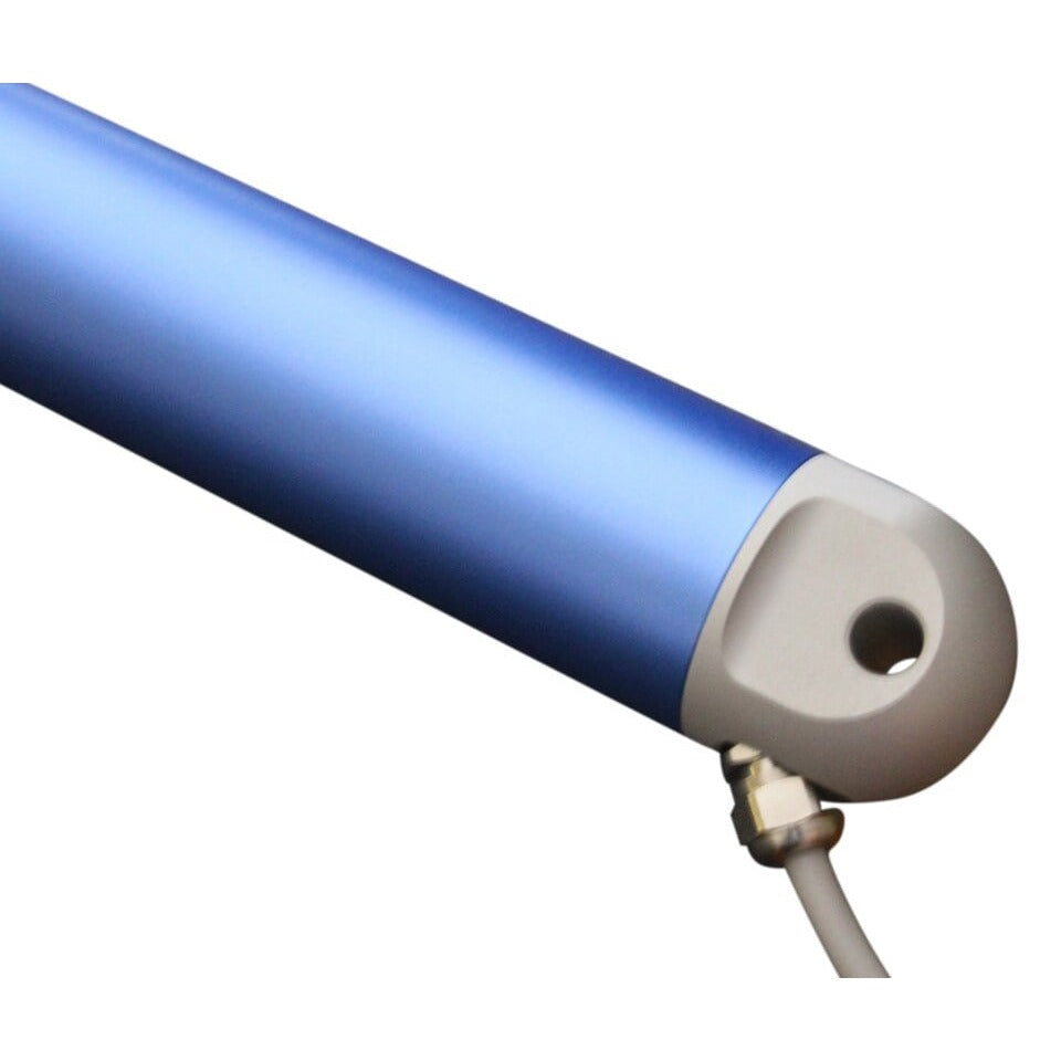
The Bullet Series 50 Cal. Linear Actuator was developed to have a slim, in-line motor design. These units have built-in hall effect sensors, which allow for synchronization, position, and speed control. The Hall effect feedback is vital to applications where multiple actuators must travel in sync. Popular within robotics, manufacturing, marine, off-road vehicles, and home automation.
*674 lbs will no longer be available once sold out.
*Product is now manufactured in silver
To synchronous 2 or more actuators together to run at exactly the same speed, we recommend our Control board FCB-1 for the ultimate Actuator control. This gives you complete actuator control including adjusting limits, speed, and even a series of timer functions to be able to time when an Actuator opens and closes.
CAD models of this actuator can be found under Resources/3D Files. For further information review the specifications and technical drawings (below) or visit our tutorials page for instructions on how to use this actuator with switches, remotes, speed controllers, and Arduino.
Tech Note: Hall Effect Sensors were modified between 2020 and 2021 production runs; previous HE Sensors had 12 magnet pairs, the current HE Sensor has 3 pairs. Please reference our Hall Effect Sensor Tutorial for PLC programming.
Accessories sold separately include: Remote Controls - Switches - Micro-Controllers - Power Supplies
| FA-BH50-500-12-(S) | FA-BH50-674-12-(S) | FA-BH50-1124-12-(S) | |
|---|---|---|---|
| Push/Pull Force | 500 lbs. | 674 lbs. | 1124 lbs. |
| Static Force | 800 lbs. | 808 lbs. | 1348 lbs. |
| Speed ("/s) | 0.48 | 0.145 | 0.08 |
| Gear Ratio | 51:1 | 50:1 | 100:1 |
| Voltage | 12V | 12V | 12V |
| Max Current at full load | 10A | 5.44A | 7.26A |
| Number of Hall magnet | 12PPR | 12PPR | 12PPR |
| Pitch of Leadscrew | P4.0*1T | P2.5*2T | P2.5*1T |
| Revolutions per inch stroke (25.4mm) | 6.35 | 5.08 | 10.16 |
| Hall Sensor pulses per revolution | 612 PPR | 1668 PPR | 1668 PPR |
| Duty Cycle | 25% | ||
| Operating Temp. Range | -4°F to 149°F (-20°C to 65°C) | ||
| Protection Class | IP66 | ||
| No Load Noise Level | 50-70 dBA (1') | ||
| Diameter | 1.97" (50mm) | ||
| Outer Housing Material | Aluminum 6061 | ||
| Expansion Rod Material | Stainless Steel 304 | ||
| Limit Switch | Built-In non-adjustable | ||
| Feedback | Hall Effect Sensor | ||
| Hall Sensor Pulses per Inch of Travel | (16,946 - 1124lbs model), (8,473 - 674lbs model), (3,886 - 500lbs model) | ||
| Hall Sensor Pulses per mm | (667 - 1124lbs model), (333 - 674lbs model), (153 - 500lbs model) | ||
| Feedback Voltage | 5V | ||
| Cable Length | 1.5 feet | ||
| Brackets | MB50U, MB50 or MB50C, | ||
| FA-BH50-500-24-(S) | FA-BH50-674-24-(S) | FA-BH50-1124-24-(S) | |
|---|---|---|---|
| Push/Pull Force | 500 lbs. | 674 lbs. | 1124 lbs. |
| Static Force | 800 lbs. | 808 lbs. | 1348 lbs. |
| Speed at full load ("/s) | 0.48 | 0.145 | 0.08 |
| Gear Ratio | 51:1 | 50:1 | 100:1 |
| Voltage | 24V | 24V | 24V |
| Max Current at full load | 5.5A | 2.72A | 3.63A |
| Number of Hall magnet | 12PPR | 12PPR | 12PPR |
| Pitch of Leadscrew | P4.0*1T | P2.5*2T | P2.51T |
| Revolutions per inch stroke (25.4mm) | 6.35 | 5.08 | 10.16 |
| Hall Sensor pulses per revolution | 516 PPR | 1668 PPR | 1668 PPR |
| Duty Cycle | 25% | ||
| Operating Temp. Range | -4°F to 149°F (-20°C to 65°C) | ||
| Protection Class | IP66 | ||
| No Load Noise Level | 50-70 dB | ||
| Diameter | 1.97" (50mm) | ||
| Outer Housing Material | Aluminum 6061 | ||
| Expansion Rod Material | Stainless Steel 304 | ||
| Limit Switch | Built-In non-adjustable | ||
| Feedback | Hall Effect Sensor | ||
| Hall Sensor Pulses per Inch of Travel | (16,946 - 1124lbs model), (8,473 - 674lbs model), (3,886 - 500lbs model) | ||
| Hall Sensor Pulses per mm | (667 - 1124lbs model), (333 - 674lbs model), (153 - 500lbs model) | ||
| Feedback Voltage | 5V | ||
| Cable Length | 1.5 feet | ||
| Brackets | MB50 or MB50C | ||
| Stroke Length | Retracted Length | Extended Length | Weight (lb) |
|---|---|---|---|
| 6" | 18.21" | 24.07" | 4.85 |
| 8" | 20.18" | 28.01" | 5.25 |
| 10" | 22.14" | 31.95" | 5.6 |
| 12" | 24.11" | 35.88" | 5.95 |
| 18" | 31.99" | 49.66" | 7.25 |
| 24" | 37.89" | 61.47" | 8.15 |
| 30" | 45.77" | 75.25" | 9.45 |
| 36" | 51.67" | 87.07" | 11.1 |
| 40" | 55.61" | 94.94" | 11.35 |


