🎥 Video — Polarity Reversal: How It Works and How to Reverse a Linear Actuator
What Is Polarity Reversal?
Polarity reversal means swapping the positive (+) and negative (−) connections in a DC electrical circuit so that current flows in the opposite direction. When you reverse the polarity of a DC motor, the motor shaft spins in the opposite direction. When you reverse the polarity of a linear actuator, the actuator reverses between extending and retracting.

In a direct current (DC) circuit, current flows from positive to negative. By swapping the wire connections, current flows through the motor in the opposite direction, which reverses the magnetic forces that drive the motor shaft. This is the fundamental principle behind controlling the direction of any DC motor or actuator.
Reversing polarity can have different effects depending on the device:
- DC motors — spin in the opposite direction
- Linear actuators — reverse between extending and retracting
- Magnets — reverse their magnetic poles (repel instead of attract)
- Sensitive electronics (diodes, transistors, ICs) — can be damaged by reversed polarity, so protection circuits are important
Polarity Reversal and Linear Actuators
In the context of a linear actuator, reversing polarity reverses the motor’s rotation, which reverses the direction of the lead screw or acme screw inside the actuator. This switches the actuator between extending (pushing out) and retracting (pulling in).
This is the most common way to control actuator direction in automated machinery, robotics, home automation, marine applications, and DIY projects. All FIRGELLI linear actuators have built-in limit switches that automatically cut power to the motor when the actuator reaches the end of its stroke in either direction — even if power is still being supplied. This protects the motor and simplifies wiring because you don’t need external limit switches.
Methods to Reverse Polarity
There are several ways to reverse the polarity of a motor or actuator, each suited to different applications and budgets:
| Method | How It Works | Best For | Complexity |
|---|---|---|---|
| Swap wires manually | Physically disconnect and reconnect the +/− wires in reverse | Testing, one-time setup | None |
| DPDT rocker switch | A center-off double-pole switch wired as an H-bridge reverses polarity with a flip | Simple manual control, DIY projects | Low |
| DPDT relay | An electrically controlled relay that swaps connections when its coil is energized | Automated systems, remote control, Arduino/microcontroller projects | Medium |
| H-bridge driver IC | An integrated circuit (L293D, L298N, etc.) with four transistor switches for bidirectional motor control | Microcontroller-driven projects, robotics, variable speed control | Medium–High |
| Dedicated actuator controller | A purpose-built controller with built-in relays, touchscreen, and advanced features | Multi-actuator systems, timed cycling, synchronized operation | Low (plug-and-play) |
The video below explains the fundamentals of polarity reversal and demonstrates how each method works with a linear actuator:
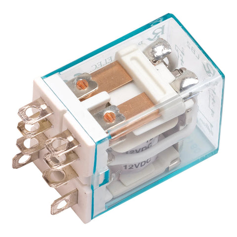
DPDT Relays: The Standard Method for Reversing Polarity
The most common method for reversing the polarity of a motor or actuator in an automated system is a DPDT (Double Pole Double Throw) relay. A DPDT relay has two sets of changeover contacts — when the relay coil is energized, both sets switch simultaneously, which swaps the positive and negative connections to the motor.
How a DPDT Relay Reverses Polarity
When wired in an H-bridge configuration, a DPDT relay works like this:
- Relay de-energized (off): The normally-closed (NC) contacts connect power to the motor in one direction — the actuator extends
- Relay energized (on): The contacts switch to normally-open (NO), reversing the positive and negative connections — the actuator retracts
- Both contacts in same state: No potential difference across the motor, so it stops (braking position)
DPDT relays are available in electromechanical, solid-state, and hybrid designs. For linear actuator applications, use a relay rated for at least 1.5× the actuator’s maximum current draw to handle inrush current and back-EMF spikes safely.
Browse FIRGELLI’s relay collection or the dedicated 12V DPDT relay for actuator applications.
This video demonstrates how to wire a DPDT relay for actuator polarity reversal:
Actuator Controllers with Built-In Polarity Reversal
For applications that need more than simple extend/retract switching, FIRGELLI’s dedicated actuator controllers have DPDT relays built in that handle polarity reversal automatically. These controllers add features that would be complex to wire manually:
| Controller | Channels | Key Features | Best For |
|---|---|---|---|
| FCB-1 | Up to 4 | Synchronized multi-actuator control, Hall Effect feedback, battery backup, programmable positions | Multi-actuator synchronized systems (camper roofs, hatches, platforms) |
| FCB-2 | 2 | LCD touchscreen, timer relay for automatic cycling, remote control, programmable speed | Automated cycling applications, timed extend/retract, remote operation |
These controllers take over the full control routine for you — including reversing polarity, controlling speed, timing extend/retract cycles, and coordinating multiple actuators to move in sync. Once configured via the onboard touchscreen, the controller handles everything automatically.

Limitations and Safety Considerations
Reversing polarity is straightforward, but there are important considerations to keep the system safe and long-lasting:
Stop Before Reversing
When a DC motor is running at full speed and you instantly reverse the voltage, the motor acts as a generator momentarily — producing a large back-EMF (electromotive force) spike that can stress motor windings, brushes, relay contacts, and connected electronics. Best practice is to allow the motor to stop briefly before applying reverse polarity. FIRGELLI actuators with built-in limit switches handle this automatically at end of stroke.
Current Rating
Switches, relays, and drivers must be rated for the motor’s maximum current draw, not just its normal running current. Actuators draw significantly more current at startup and under heavy load (stall current). Select components rated at least 1.5× the stall current.
Polarity-Sensitive Components
While DC motors and actuators are not damaged by reversed polarity (they simply run in the opposite direction), many electronic components are polarity-sensitive. Diodes, transistors, electrolytic capacitors, and integrated circuits can be destroyed by reversed voltage. If your circuit includes sensitive electronics alongside the motor, use protection diodes and ensure the polarity reversal only affects the motor leads.
Wiring and Fusing
Always use wire gauges appropriate for the current draw and length of run. For guidance on selecting the right wire size, see our AWG Wire Gauge Chart. Add an inline fuse rated just above the actuator’s maximum current to protect against short circuits.
Related Wiring Guides, Controllers, and Products
Wiring and Control Guides
- How to Control an Actuator with a Switch or Relay — detailed wiring guide for DPDT switch and relay setups
- How to Control an Actuator with an Arduino — microcontroller-based H-bridge control with code examples
- AWG Wire Gauge Chart — complete wire size reference with ampacity ratings
- Voltage Drop Calculator — verify your wire gauge handles the current over the run length
- Types of Linkages Guide — mechanical linkage mechanisms for actuator mounting
Controllers and Relays
- FCB-1 Synchronous Controller — 4-channel synchronized actuator control with built-in polarity reversal
- FCB-2 Controller with LCD — touchscreen controller with timer relay and remote control
- 12V DPDT Relay — single relay for DIY polarity reversal circuits
- All Relays — full relay collection for actuator and motor control
Linear Actuators
- All Linear Actuators — browse by force, stroke, speed
- Bullet 50 Cal Series — heavy-duty IP66, built-in Hall Effect feedback
- Feedback Rod Actuators — position feedback for precise control
- Super Duty Actuators — highest force ratings for heavy-duty applications


