Introduction: Why Voltage Drop Matters for Electric Linear Actuator Performance
When installing linear actuators in your project—whether it's a custom TV lift, automated standing desk, or industrial machinery—one critical electrical phenomenon can significantly impact performance: voltage drop. As electrical current travels through wire, resistance causes a loss of voltage between the power supply and your actuator. This isn't a defect or malfunction—it's a fundamental characteristic of electrical conductors governed by Ohm's Law.
🎥 Video — Voltage Drop Calculator - A Comprehensive Guide for Electric Actuator Performance
For many DIY enthusiasts and engineers alike, voltage drop is an overlooked factor during installation planning. However, excessive voltage drop can reduce actuator speed, diminish available force, cause overheating, and even lead to premature component failure. When you're running long wire lengths to reach an outbuilding, mounting position, or remote installation point, understanding and calculating voltage drop becomes essential to ensuring your system operates as designed.
This comprehensive guide explains the physics behind voltage drop, the factors that influence it, and provides practical calculation methods to optimize your actuator installations. We've also included an interactive voltage drop calculator specifically tailored for DC systems commonly used with electric linear actuators. Whether you're installing a single micro linear actuator or designing a complex multi-actuator system, this guide will help you size your wiring correctly and maintain optimal performance.
Understanding Voltage Drop: The Fundamentals
Voltage drop refers to the reduction in electrical potential (voltage) that occurs as current flows through a conductor. Every conductor—copper wire, aluminum wire, or any other material—has inherent resistance that opposes the flow of electrons. When current encounters this resistance, energy is dissipated as heat, and the voltage at the load end is lower than at the source end.
Think of voltage drop like water pressure loss in a long garden hose. The water pressure at the faucet is higher than at the nozzle because friction against the hose walls reduces pressure along the length. Similarly, electrical resistance in wire reduces voltage over distance. This analogy helps explain why longer wires experience greater voltage drop—more resistance is encountered over longer distances.
What Causes Voltage Drop?
The primary cause of voltage drop is the inherent resistance of the conductor material. In DC (direct current) circuits—which are standard for electric linear actuators—resistance is straightforward. In AC (alternating current) systems, the situation becomes more complex due to inductance and capacitance effects, collectively called impedance. Since most actuator systems operate on 12V, 24V, or 36V DC power, we'll focus primarily on DC resistance calculations throughout this guide.
The resistance of a wire depends on four key factors: the conductor material (copper vs. aluminum), the cross-sectional area (wire gauge), the length of the wire run, and the operating temperature. Each of these variables can be controlled during installation to minimize voltage drop and maintain system performance.
Effects of Voltage Drop on Actuator Performance
Voltage drop directly impacts the performance characteristics of electric linear actuators. When insufficient voltage reaches the actuator motor, several problems can occur:
- Reduced Speed: Actuators operate slower than their rated specifications when supplied with lower voltage. A 12V actuator receiving only 10.5V due to voltage drop will move noticeably slower.
- Decreased Force Output: The force an actuator can exert is directly related to the current available to its motor. Voltage drop limits current delivery, reducing pushing and pulling capacity.
- Motor Overheating: When motors receive insufficient voltage, they draw higher current to attempt maintaining performance, generating excess heat that can damage windings.
- Control Issues: Feedback actuators with position sensors may experience erratic behavior if voltage fluctuates outside acceptable ranges.
- Premature Failure: Chronic under-voltage conditions stress electrical components, shortening operational lifespan.
Industry standards generally recommend limiting voltage drop to 3-5% of the supply voltage for optimal performance. For a 12V system, this means keeping voltage drop below 0.36V to 0.6V. For 24V systems, the allowable drop is 0.72V to 1.2V. Staying within these parameters ensures your actuators perform reliably according to their specifications.
Factors Influencing Voltage Drop
Understanding the variables that affect voltage drop allows you to make informed decisions during system design and installation. The four primary factors—conductor material, wire size, wire length, and current load—can be optimized to minimize voltage losses and maximize actuator performance.
Conductor Material: Copper vs. Aluminum
The material composition of electrical wire dramatically affects its conductivity and resistance. Copper and aluminum are the two most common conductor materials, each with distinct characteristics:
Copper is the preferred material for most actuator installations. It has excellent electrical conductivity (approximately 1.68 × 10⁻⁸ Ω·m resistivity), good mechanical strength, and superior resistance to corrosion. Copper wire is easier to work with, solders reliably, and maintains consistent performance over a wide temperature range. For industrial actuator applications requiring reliability and longevity, copper is typically the best choice despite higher material costs.
Aluminum wire offers a cost-effective alternative for very long runs or budget-conscious applications. However, aluminum has approximately 61% of copper's conductivity (2.82 × 10⁻⁸ Ω·m resistivity), meaning you need larger gauge aluminum wire to match copper's performance. Aluminum also has lower tensile strength, is more prone to oxidation at connections, and requires special connectors and techniques to prevent galvanic corrosion. For most linear actuator installations, the benefits of copper outweigh the cost savings of aluminum.
Wire Size and AWG Gauge Standards
Wire gauge—specifically the American Wire Gauge (AWG) system—quantifies wire diameter and cross-sectional area. Understanding AWG is crucial because it directly determines resistance and current-carrying capacity (ampacity).

The AWG system can be counterintuitive: smaller AWG numbers indicate larger wire diameters. For example, 10 AWG wire has a larger diameter and lower resistance than 18 AWG wire. This inverse relationship confuses many first-time installers, so it's worth emphasizing: lower AWG numbers mean thicker wire with less resistance.
Key relationships in the AWG system include:
- Every decrease of 6 gauge numbers doubles the wire diameter (e.g., 12 AWG is twice the diameter of 18 AWG)
- Every decrease of 3 gauge numbers doubles the cross-sectional area (e.g., 12 AWG has twice the area of 15 AWG)
- Every decrease of 10 gauge numbers increases cross-sectional area by a factor of 10 (e.g., 10 AWG has 10× the area of 20 AWG)
Common wire gauges for linear actuator installations range from 18 AWG for small micro actuators with short runs, to 12 AWG or 10 AWG for higher-current actuators or long wire runs. The voltage drop calculator later in this guide will help you determine the optimal gauge for your specific application.
Wire Length: Distance Matters
Wire length has a linear relationship with resistance—double the length, double the resistance, double the voltage drop. This makes distance planning critical for installations where actuators are far from the power source.
An important consideration often overlooked: when calculating voltage drop, you must account for the total circuit length, which includes both the positive and negative conductors. If your actuator is 25 feet from the power supply, the total wire length is 50 feet (25 feet out on the positive wire, 25 feet back on the negative wire). This doubling effect is why our voltage drop formula includes a factor of 2.
For installations requiring very long runs—such as automated barn doors, remote gate operators, or outdoor equipment—voltage drop becomes the dominant design consideration. In such cases, you might need to use wire several gauges larger than would otherwise be necessary, or consider installing the control box and power supply closer to the actuator location.
Current Load and Ampacity
The amount of current (measured in amperes) flowing through a wire directly affects voltage drop. Higher current through the same wire produces proportionally higher voltage drop, as described by Ohm's Law (V = I × R). This is why actuators with higher force ratings—which typically draw more current—require more careful wire sizing.
Every wire size has a maximum safe current-carrying capacity called its ampacity. Ampacity ratings consider not just voltage drop, but also heat dissipation and safety factors. Exceeding a wire's ampacity can cause dangerous overheating, insulation degradation, and fire hazards. For this reason, National Electrical Code (NEC) standards provide ampacity tables that must be followed for permanent installations.
Typical current draws for linear actuators vary widely:
- Small micro actuators: 1-3 amps
- Standard actuators: 3-8 amps
- High-force industrial actuators: 10-20 amps or more
Always check your actuator's specifications for peak current draw, not just nominal operating current. Actuators draw maximum current during startup and when stalling against a load, which may be significantly higher than steady-state current.
Temperature and Cable Bundling Effects
Two additional factors affect wire resistance and performance: operating temperature and cable bundling. As wire temperature increases, electrical resistance increases—copper's resistance rises approximately 0.393% per degree Celsius. This means wire in hot environments or carrying heavy loads (which self-heats) will have higher resistance and greater voltage drop than the same wire at room temperature.
Cable bundling—running multiple wires together in conduit or wire harnesses—reduces each wire's ability to dissipate heat. Bundled cables retain heat, increasing temperature and resistance. NEC ampacity tables include derating factors for bundled conductors. For critical applications, consider separating power wires from other cables, using wire with higher temperature ratings, or increasing wire gauge to compensate for thermal effects.
Calculating Voltage Drop: The Mathematics
Understanding the mathematical principles behind voltage drop empowers you to predict and prevent performance problems before installation. While our online calculator automates these computations, understanding the underlying formulas helps you make better design decisions.
Ohm's Law: The Foundation
All voltage drop calculations stem from Ohm's Law, which states that voltage (V) equals current (I) multiplied by resistance (R):
V = I × R
For voltage drop calculations, we're specifically interested in the voltage lost across the wire's resistance:
Vdrop = I × Rwire
Where:
- Vdrop = Voltage drop (in volts)
- I = Current through the wire (in amperes)
- Rwire = Resistance of the wire (in ohms)
DC Voltage Drop Formula
For DC circuits (which include virtually all electric linear actuator systems), the practical voltage drop formula accounts for the complete circuit path—both the positive and negative conductors:
Vdrop = 2 × I × R × L
Where:
- 2 = Factor accounting for both conductors (positive and negative wire)
- I = Current in amperes
- R = Wire resistance per unit length (in ohms per foot or ohms per meter)
- L = One-way length of the wire run
The factor of 2 is critical—it's easy to forget that current must travel to the load through one wire and return through another, doubling the effective resistance.
Calculating Wire Resistance
Wire resistance can be calculated from first principles using the material's resistivity and the wire's physical dimensions:
R = ρ × (L / A)
Where:
- R = Resistance in ohms
- ρ = Resistivity of the conductor material (1.68 × 10⁻⁸ Ω·m for copper)
- L = Length of the conductor
- A = Cross-sectional area of the conductor
However, for practical purposes, it's far simpler to reference standard AWG resistance tables. These provide resistance per unit length for each wire gauge, eliminating complex calculations.
AWG Wire Resistance Reference Table
The following table provides critical specifications for common AWG wire sizes. The resistance values are for copper wire at 20°C (68°F):
| AWG | Diameter (inches) | Diameter (mm) | Area (mm²) | Resistance (Ω/1000ft) | Resistance (Ω/km) |
|---|---|---|---|---|---|
| 2 | 0.2576 | 6.544 | 33.6 | 0.1563 | 0.5127 |
| 4 | 0.2043 | 5.189 | 21.2 | 0.2485 | 0.8152 |
| 6 | 0.1620 | 4.115 | 13.3 | 0.3951 | 1.296 |
| 8 | 0.1285 | 3.264 | 8.37 | 0.6282 | 2.061 |
| 10 | 0.1019 | 2.588 | 5.26 | 0.9989 | 3.277 |
| 12 | 0.0808 | 2.053 | 3.31 | 1.588 | 5.211 |
| 14 | 0.0641 | 1.628 | 2.08 | 2.525 | 8.286 |
| 16 | 0.0508 | 1.291 | 1.31 | 4.016 | 13.17 |
| 18 | 0.0403 | 1.024 | 0.823 | 6.385 | 20.95 |
| 20 | 0.0320 | 0.812 | 0.518 | 10.15 | 33.31 |
| 22 | 0.0253 | 0.644 | 0.326 | 16.14 | 52.96 |
| 24 | 0.0201 | 0.511 | 0.205 | 25.67 | 84.22 |
Notice how resistance increases dramatically as wire gauge gets smaller (higher AWG numbers). An 18 AWG wire has approximately four times the resistance per foot compared to 12 AWG wire—a significant difference that directly impacts voltage drop over distance.
Practical Example: Voltage Drop Calculation Walkthrough
Let's work through a detailed example to demonstrate how voltage drop calculations apply to real-world linear actuator installations. This example will show you the step-by-step process for determining voltage drop and power loss.
Example Scenario
You're installing a linear actuator to automate a cabinet door. The specifications are:
- Supply Voltage: 12V DC
- Actuator Current Draw: 12 amperes (peak)
- Wire Length: 50 feet (one-way distance from power supply to actuator)
- Wire Gauge: 12 AWG copper wire
Step-by-Step Calculation Process
Step 1: Gather Wire Specifications
From the AWG resistance table above, 12 AWG copper wire has a resistance of 1.588 Ω per 1000 feet. To find resistance per foot, divide by 1000:
Resistance per foot = 1.588 Ω ÷ 1000 = 0.001588 Ω/ft
Step 2: Calculate Total Wire Resistance
For a 50-foot one-way run, the total circuit length (positive and negative conductors) is 100 feet:
Total resistance = 0.001588 Ω/ft × 100 ft = 0.1588 Ω
Alternatively, using the simplified formula approach:
R = 2 × (resistance per 1000 ft ÷ 1000) × length in feet
R = 2 × (1.588 ÷ 1000) × 50 = 0.1588 Ω
Step 3: Calculate Voltage Drop
Using Ohm's Law (V = I × R):
Vdrop = 12 A × 0.1588 Ω = 1.906 V
Step 4: Calculate Voltage at Actuator
Voltage delivered to actuator = Supply voltage - Voltage drop
Voltage at actuator = 12V - 1.906V = 10.094V
Step 5: Calculate Percentage Voltage Drop
Percentage drop = (Voltage drop ÷ Supply voltage) × 100%
Percentage drop = (1.906V ÷ 12V) × 100% = 15.9%
Step 6: Calculate Power Loss
Power lost as heat in the wire:
Ploss = Vdrop × I = 1.906V × 12A = 22.87 watts
Interpreting the Results
This example reveals a significant problem: a 15.9% voltage drop far exceeds the recommended 3-5% maximum. The actuator would receive only 10.1V instead of the rated 12V, resulting in reduced speed and force output. Additionally, nearly 23 watts of power are being wasted as heat in the wire—energy that should be powering the actuator.
Solutions to reduce voltage drop in this scenario:
- Increase wire gauge: Using 10 AWG instead of 12 AWG would reduce resistance by approximately 37%, dropping voltage loss to about 1.2V (10% drop)
- Increase wire gauge further: Using 8 AWG would reduce voltage drop to approximately 0.75V (6.3% drop)—much more acceptable
- Reduce wire length: Relocate the power supply closer to the actuator installation point
- Use higher supply voltage: If the actuator supports 24V operation, the percentage voltage drop would be halved for the same absolute voltage loss
This example demonstrates why voltage drop calculations should be performed before purchasing wire and installing your system. The small additional cost of larger gauge wire is far less expensive than troubleshooting performance problems after installation.
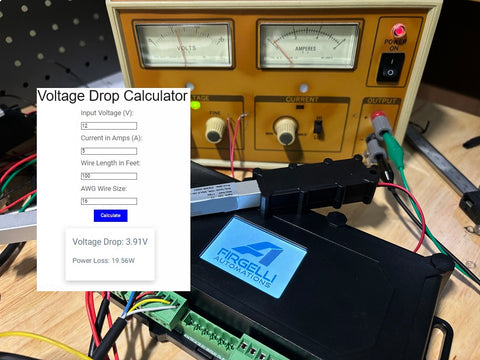
Interactive Voltage Drop Calculator
Use this calculator to determine the voltage drop and power loss for your specific linear actuator installation. Simply enter your system parameters, and the calculator will compute the results instantly. This tool is specifically designed for DC systems and copper wire—the standard configuration for electric linear actuator installations.
How to use this calculator:
- Enter your supply voltage (typically 12V, 24V, or 36V for actuator systems)
- Enter the actuator's current draw in amperes (check the actuator specifications for peak current)
- Enter the one-way wire length in feet (distance from power supply to actuator)
- Select the wire gauge you're planning to use (or experiment with different gauges to find the optimal size)
- Click "Calculate" to see voltage drop, delivered voltage, percentage drop, and


