Controlling the speed of linear actuators is essential for applications ranging from automated furniture and robotics to industrial machinery and home automation projects. While many actuators operate at a fixed speed determined by their motor and gearbox configuration, the ability to vary speed on demand opens up new possibilities for precise motion control, synchronized movement, and optimized power consumption. The FA-SC1 Speed Controller provides a versatile, cost-effective solution for adjusting the speed of 12V linear actuators without the complexity of programmable motor controllers or the expense of variable frequency drives.
Whether you're building a TV lift mechanism that requires smooth, quiet operation or coordinating multiple actuators in a custom automation project, understanding how to properly configure and use the FA-SC1 opens up considerable flexibility. This controller supports three distinct control methods: manual DIP switch selection for fixed speed settings, analog potentiometer control for hands-on variable adjustment, and microcontroller integration for programmable, automated speed control. Each method serves different use cases, from simple installations to sophisticated Arduino-based automation systems.
This comprehensive guide walks through every aspect of using the FA-SC1 Speed Controller, from initial setup and wiring to advanced applications like near-synchronous control of multiple actuators. We'll cover proper connection procedures, safety considerations, speed configuration methods, and practical troubleshooting to help you achieve reliable, precise speed control in your linear actuator projects.
FA-SC1 Circuit Board Overview and Connection Points
The FA-SC1 Speed Controller features a compact circuit board design with clearly labeled connection terminals and configuration options. Understanding the board layout is crucial for proper installation and avoiding common wiring mistakes that could damage the controller or connected actuator.
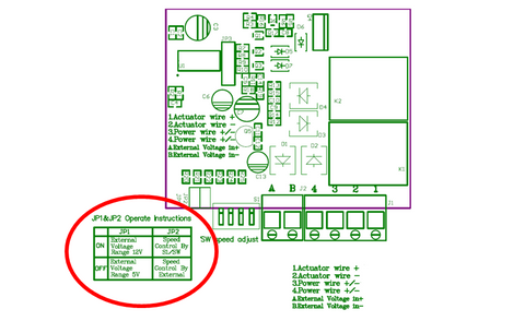
The board includes three sets of screw terminals and two jumper pin locations:
- Screw Terminals 1 and 2: These connect directly to your linear actuator's motor leads. Polarity matters here—reversing these connections will reverse the actuator's direction of travel.
- Screw Terminals 3 and 4: These connect to your 12V DC power supply. The controller requires a power supply capable of delivering the full current draw of your actuator, which can range from 3A for smaller units to 10A for larger models.
- Screw Terminals A and B: These optional terminals accept an external analog voltage signal (either 0-5V or 0-12V) for variable speed control from a potentiometer, Arduino, or PLC.
- Jumper Pin 1: This selects the voltage range for external control signals. Remove this jumper when using 5V control signals (such as from an Arduino's PWM output). Leave it connected when using 12V control signals.
- Jumper Pin 2: This selects the control mode. Leave it connected for DIP switch control (manual mode). Remove it when using external voltage control from terminals A and B.
The four-position DIP switch array provides manual speed selection with 16 discrete speed settings, giving you precise control over actuator velocity without requiring any additional components or programming.
Critical Safety Warnings and Current Limitations
Before connecting the FA-SC1 to your linear actuator system, understanding its operational limits and safety requirements is essential to prevent permanent damage to the controller.
Polarity Protection: The FA-SC1 does not include reverse polarity protection on the external control voltage inputs (terminals A and B). Reversing the polarity on these terminals will cause immediate and permanent damage to the control circuitry. Always verify polarity with a multimeter before making connections, especially when working with unmarked wires or custom cables.
Current Capacity Limitations: The FA-SC1 is rated for a maximum continuous current of 10 amperes. This limitation has important implications for actuator selection and application design. Even smaller linear actuators can draw significant inrush current during startup—sometimes 2-3 times their rated running current. For this reason, never connect two actuators to a single FA-SC1 controller, even if their combined running current would theoretically stay below 10A. The startup surge from dual actuators almost always exceeds the controller's capacity and will damage the unit.
When selecting actuators for use with the FA-SC1, consider both the rated current and the application's duty cycle. High-force industrial actuators or those frequently operating under maximum load should be paired with controllers that provide appropriate current headroom. For applications requiring multiple actuators, use one FA-SC1 per actuator, or consider alternative solutions like synchronized feedback actuators with dedicated multi-channel control systems.
Heat Dissipation: During operation, especially at lower speed settings where the controller uses PWM (pulse width modulation) to reduce effective voltage, the FA-SC1 will generate heat. Ensure adequate ventilation around the controller and avoid mounting it in enclosed spaces without airflow. If the controller becomes too hot to touch comfortably, reduce the load or improve cooling.
Manual Speed Control Using DIP Switch Settings
The DIP switch method provides the simplest way to set actuator speed, requiring no additional components beyond the controller, actuator, and power supply. This approach works well for applications where speed doesn't need to change during operation or where you want to set a fixed speed for consistent performance.
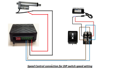
Wiring Configuration for DIP Switch Control
For DIP switch control, make the following connections:
- Connect your actuator's motor leads to screw terminals 1 and 2
- Connect your 12V power supply positive lead to screw terminal 3
- Connect your power supply ground/negative lead to screw terminal 4
- Ensure both jumper pins 1 and 2 remain connected (factory default position)
- Leave terminals A and B disconnected

Understanding the 16 Speed Settings
The four DIP switches create a binary configuration allowing 16 distinct speed settings. Each switch represents a binary digit, with switch 1 being the least significant bit and switch 4 being the most significant bit. When a switch is in the "ON" position, it contributes to that binary value; "OFF" contributes zero.
Speed setting 0000 (all switches OFF) produces the slowest speed—approximately 15-20% of maximum speed depending on load. Speed setting 1111 (all switches ON) produces full speed, equivalent to running the actuator directly from 12V without the controller. The intermediate 14 settings provide graduated speeds between these extremes, though the relationship between switch settings and actual speed is not perfectly linear due to motor characteristics and PWM behavior.
To find your optimal speed setting:
- Start with a middle setting like 1000 (switch 4 ON, others OFF)
- Observe the actuator's speed and smoothness of operation
- Adjust incrementally up or down until you achieve the desired performance
- Note that lower speeds may exhibit slightly less torque and potentially rougher operation depending on your actuator's motor design
Applications like automated window openers or standing desks often benefit from slower speeds (settings 0011 to 0111) for smoother, quieter operation, while applications requiring faster cycle times can use higher settings.
Variable Speed Control Using a Potentiometer
For applications requiring hands-on speed adjustment without programming, a potentiometer provides intuitive, continuously variable speed control. This method is ideal for test benches, manual positioning systems, or any application where an operator needs to adjust speed on the fly.
Selecting the Right Potentiometer
A standard 10kΩ linear taper potentiometer works well for this application. Rotary potentiometers are most common, but slide potentiometers can also be used if your control panel layout benefits from linear motion. The resistance value isn't critical—anything from 5kΩ to 50kΩ will function properly—but 10kΩ provides good resolution and is readily available.
Choose between 5V or 12V operation based on your available power supply. Using 5V draws less current through the potentiometer and may provide smoother low-speed control, while 12V eliminates the need for a separate 5V supply.
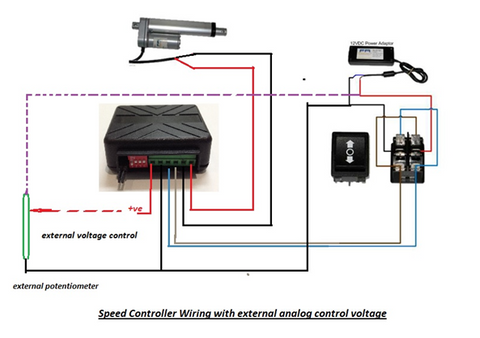
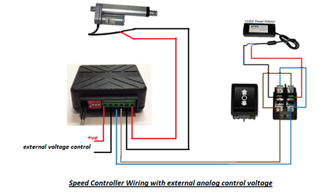
Wiring the Potentiometer Circuit
To configure the FA-SC1 for potentiometer control:
- Remove jumper pin 2 to disable DIP switch control and enable external voltage mode
- If using 5V control, remove jumper pin 1; if using 12V control, leave jumper pin 1 connected
- Connect the potentiometer's outer terminals to your voltage source: one terminal to positive (5V or 12V), the other to ground
- Connect the potentiometer's center (wiper) terminal to screw terminal A on the FA-SC1
- Connect screw terminal B to the same ground as the voltage source
- Connect your actuator to terminals 1 and 2, and main power to terminals 3 and 4 as usual
When you rotate the potentiometer, it creates a variable voltage divider, producing a voltage between 0V and your supply voltage (5V or 12V). The FA-SC1 interprets this voltage and adjusts the actuator's speed proportionally. Rotating toward the voltage source increases speed; rotating toward ground decreases speed.
This setup works excellently for workbench testing, allowing you to dial in the perfect speed for your application before committing to a fixed DIP switch setting. It's also useful in finished projects where user-adjustable speed is a desired feature.
Microcontroller and PLC Integration for Programmable Speed Control
The most powerful control method involves using the FA-SC1 with a microcontroller like an Arduino, Raspberry Pi, or industrial PLC. This approach enables programmatic speed control based on sensors, timers, or complex automation logic.
Arduino-Based Speed Control
Arduino boards typically operate at 5V logic levels, making them ideal for controlling the FA-SC1. To implement Arduino control:
- Remove jumper pin 2 to enable external voltage control
- Remove jumper pin 1 to configure for 5V operation
- Connect an Arduino PWM pin to screw terminal A
- Connect Arduino GND to screw terminal B
- Wire your actuator and main 12V power supply to the appropriate terminals
The Arduino's analogWrite() function outputs a PWM signal that, when filtered by the FA-SC1's input circuitry, produces the analog voltage that controls speed. A value of 0 produces minimum speed, while 255 produces maximum speed:
analogWrite(speedPin, 128); // Sets approximately 50% speed
This method enables sophisticated control strategies:
- Ramped speed changes for smooth starts and stops
- Sensor-based speed adjustment (slowing as the actuator approaches a target position)
- Time-based speed profiles for complex motion sequences
- Speed modulation based on load sensing or environmental conditions
Industrial PLC Integration
For industrial applications, PLCs provide robust, reliable control in harsh environments. Most PLCs offer both 5V and 12V analog outputs or PWM outputs that can be configured appropriately. Configure the FA-SC1's jumper pins to match your PLC's output voltage (jumper 1 removed for 5V, connected for 12V), and connect the PLC's analog output to terminal A with ground to terminal B.
Many modern PLCs support proportional control algorithms that can automatically adjust actuator speed based on position feedback, load cells, or other process variables, creating sophisticated closed-loop control systems.
Near-Synchronous Control of Multiple Linear Actuators
Many automation projects require two or more linear actuators to move in coordination—for example, lifting opposite ends of a platform or opening dual hatch doors. While perfect synchronization requires feedback actuators with position sensing, the FA-SC1 can achieve acceptably close synchronization for applications with less demanding requirements.
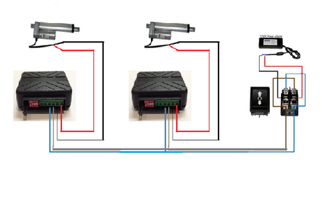
Speed Matching Method for Non-Feedback Actuators
When working with standard actuators that lack internal position feedback, you can achieve near-synchronous operation by carefully matching speeds across multiple units:
- Install one FA-SC1 speed controller per actuator—never attempt to run multiple actuators from one controller
- Wire each controller identically, with all actuators powered from the same power supply for voltage consistency
- Start with identical DIP switch settings on all controllers (or identical external voltage inputs)
- Operate the actuators through their full stroke while observing their relative positions
- If one actuator leads or lags, adjust its speed controller incrementally until the actuators track closely
- Repeat the test and fine-tune until acceptable synchronization is achieved
Understanding Synchronization Limitations
It's critical to understand that this method cannot achieve perfect synchronization. Even with carefully matched speeds, actuators will drift relative to each other over time due to:
- Manufacturing tolerances in motor windings and gearbox ratios
- Variations in friction and wear between units
- Differences in load distribution (one actuator may carry more weight than another)
- Temperature effects on motor performance
- Slight voltage drops across different wiring paths
For applications requiring true synchronization—where position error must remain within a few millimeters over many cycles—invest in bullet actuators or optical feedback actuators paired with an FA-SYNC-2 or FA-SYNC-4 synchronization control board. These systems use position feedback to actively correct any drift, maintaining precise synchronization regardless of load variations or mechanical differences.
The speed-matching method works acceptably for applications like dual-actuator TV lifts, adjustable workbenches, or gate openers where a few millimeters of position difference is tolerable and where the actuators return to hard stops (fully extended or retracted) regularly, allowing positions to re-synchronize.
Troubleshooting and Optimization Tips
Common Issues and Solutions
Actuator not responding: First verify power supply voltage at terminals 3 and 4—should measure 12V DC. Check that jumper pins are configured correctly for your control method. Verify actuator connections at terminals 1 and 2 are secure.
Speed control not working: If using external voltage control, confirm jumper pin 2 is removed. Measure voltage at terminals A and B to verify your potentiometer or microcontroller is outputting correctly. Ensure jumper pin 1 matches your control voltage (removed for 5V, connected for 12V).
Rough or jerky operation at low speeds: This is normal for some actuators, particularly those with brushed DC motors and lower-quality gearboxes. Try slightly increasing speed. Ensure the actuator isn't binding mechanically and that mounting brackets allow proper alignment throughout the stroke.
Controller getting hot: Verify your actuator's current draw doesn't exceed 10A. Improve ventilation around the controller. Consider using a larger actuator with lower current draw if your application allows.
Performance Optimization Strategies
To get the best performance from your FA-SC1 setup:
- Use appropriately sized wire for your actuator's current draw—minimum 18 AWG for 5A, 16 AWG for 8A, 14 AWG for 10A
- Keep wire runs as short as practical to minimize voltage drop
- Use a power supply with at least 20% more capacity than your actuator's maximum draw
- For microcontroller applications, implement software ramping—gradually changing speed rather than instantaneous changes—for smoother operation
- In dusty or humid environments, consider mounting the controller in a protective enclosure with the screw terminals accessible for connections
- For critical applications, maintain a spare FA-SC1 controller for quick replacement if needed
Summary and Best Practices
The FA-SC1 Speed Controller provides versatile, reliable speed control for 12V linear actuators across a wide range of applications. Whether you choose the simplicity of DIP switch control for fixed-speed operation, the flexibility of potentiometer adjustment for hands-on control, or the sophistication of microcontroller integration for programmable automation, the FA-SC1 delivers consistent performance within its rated specifications.
Key takeaways for successful implementation include respecting the 10A current limit by using one controller per actuator, carefully observing polarity requirements for external control voltages, and understanding the limitations of speed-matching for synchronous applications. When true position synchronization is required, dedicated feedback actuators with closed-loop control systems provide the necessary precision.
By following the wiring diagrams, configuring jumpers correctly for your control method, and implementing the appropriate control strategy for your application, the FA-SC1 enables precise speed adjustment that enhances the performance and versatility of your linear actuator systems.
Frequently Asked Questions
Can I use the FA-SC1 with 24V linear actuators?
No, the FA-SC1 is designed specifically for 12V DC linear actuators and power supplies. Using it with 24V actuators or power supplies will damage the controller permanently. If your application requires 24V actuators, you'll need an alternative speed controller rated for 24V operation. Always verify your actuator's voltage rating before selecting a speed controller.
Why can't I connect two small actuators to one FA-SC1 if they're both under 5A?
While the combined running current of two small actuators might be within the FA-SC1's 10A rating, the startup inrush current can be 2-3 times higher than running current for each actuator. Two actuators starting simultaneously can easily create a 15-20A surge that exceeds the controller's capacity and damages internal components. Always use one FA-SC1 per actuator for reliability and safety.
Can I achieve perfect synchronization using multiple FA-SC1 controllers?
No, the speed-matching method using multiple FA-SC1 controllers with standard actuators cannot achieve perfect synchronization. Even with carefully matched speeds, actuators will gradually drift due to manufacturing tolerances, load differences, and operating conditions. For applications requiring precise position synchronization (within a few millimeters over many cycles), use feedback actuators with optical or Hall effect sensors paired with a dedicated synchronization controller like the FA-SYNC-2 or FA-SYNC-4.
Does the FA-SC1 accept PWM input directly from an Arduino?
Yes, when jumper pin 1 is removed (for 5V operation) and jumper pin 2 is removed (for external control mode), the Arduino's PWM output connects to terminal A. The FA-SC1's input circuitry filters the PWM signal to produce the analog voltage needed for speed control. Use the analogWrite() function with values from 0 (minimum speed) to 255 (maximum speed) for proportional control.
Will reducing actuator speed also reduce its force output?
Reducing speed via the FA-SC1 slightly reduces available force, but not proportionally. The controller uses pulse width modulation to effectively reduce voltage to the motor, which can decrease torque output by approximately 10-20% at very low speed settings. However, this reduction is generally not significant for most applications. If your actuator is already operating at or near its maximum force rating, consider selecting a higher-force actuator rather than relying on a lower-force unit at full speed.
Can I use the FA-SC1 with a wireless remote control system?
The FA-SC1 controls actuator speed but doesn't directly integrate with remote control systems. To combine remote operation with speed control, use the FA-SC1 to set the actuator's speed, then control direction (extend/retract) using a separate remote control system or relay board. Many users combine an FA-SC1 set to their desired speed with a standard remote control that handles the directional switching and power on/off functions.
Will slowing down my actuator make it quieter?
In most cases, yes—reducing actuator speed with the FA-SC1 typically results in quieter operation, which is particularly beneficial for applications like TV lifts, home automation, or office furniture where noise is a concern. The reduced speed means lower motor RPM and less mechanical noise from the gearbox. However, at very low speed settings, some actuators may exhibit slightly rougher operation due to the pulsed nature of PWM control, which could potentially increase noise in some units. Experiment with different settings to find the optimal balance between speed and acoustic performance for your specific actuator model.


