Complete TVL-170 Setup Guide: Professional TV Lift Installation Made Simple
The FIRGELLI TVL-170 represents the intersection of precision engineering and practical home automation. Whether you're building a custom cabinet, retrofitting furniture, or creating a hidden TV installation from scratch, this tv lift system delivers the reliability and smooth operation you'd expect from electric linear actuation technology developed through decades of automotive and aerospace experience.
This comprehensive guide walks you through every aspect of TVL-170 setup—from understanding the critical measurements that determine success, to programming advanced features like memory positions and programmable limit switches. Unlike simple instructional manuals, we'll explain not just the "how" but the "why" behind each step, giving you the technical understanding to troubleshoot issues and optimize your installation for your specific application.
The TVL-170 arrives as a complete system with AC/DC power supply, integrated control box, wireless RF and IR remote controls, and all necessary mounting hardware. For those considering the floor-mount variant, our separate TVL-180 guide covers those specific installation requirements.

Understanding Essential TVL-170 Components and Terminology
Before beginning installation, familiarity with the TVL-170's key components and terminology ensures accurate measurements and proper setup. These terms appear throughout technical specifications and installation planning.
Stroke and Pocket: Critical Measurement Concepts
Stroke refers to the total vertical distance the lifting column travels from fully retracted to fully extended position. This measurement determines how tall a TV your system can accommodate. The minimum stroke requirement equals your TV's vertical height—the lift must travel at least this distance to bring your display fully into view.
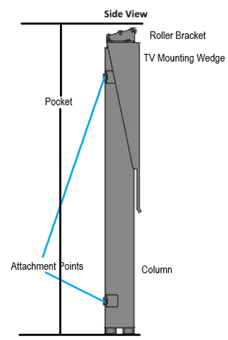
Pocket describes the interior space required to house the retracted actuator and TV when hidden from view. This "dead space" must remain completely unobstructed throughout the lift's entire range of motion. When planning cabinet dimensions, the pocket depth represents non-negotiable clearance—any interference here will bind the mechanism or damage components. Think of pocket space as the envelope of motion that must be protected within your furniture design.
The Lifting Column Assembly
The column forms the heart of the TVL-170 system—a telescoping linear actuator that converts rotary motor motion into smooth vertical travel. Rubber feet at the base provide vibration damping and protect mounting surfaces, while the column's multi-stage design extends upward with minimal deflection even at full extension. This telescoping architecture allows compact storage height while achieving substantial stroke lengths.

TV Mounting Hardware Components
The TV Mounting Wedge attaches to the top of the lift column, featuring a triangular profile with mounting holes along its widest face. This wedge geometry provides angular adjustment capability for precise TV alignment.
The TV Mounting Bracket Assembly consists of two horizontal mounting bars that attach to the wedge, plus adjustable mounting brackets that interface with VESA patterns on your TV's back panel. After attaching brackets to your TV, they slide onto the horizontal bars and secure with set screws, allowing lateral positioning adjustment before final tightening.
Pre-Installation Planning and Measurements
Successful TV lift installation begins with accurate dimensional planning. Rushing this phase leads to costly rework—measure carefully and verify clearances before cutting cabinet openings or mounting hardware.
Determining Required Stroke Length
Your TV's vertical dimension establishes the minimum stroke requirement. However, add 1-2 inches of additional stroke beyond the TV height to ensure complete emergence from the pocket and account for mounting hardware thickness. This extra travel prevents the TV from appearing to "peek out" when viewing, and provides clearance for the mounting wedge assembly.
TV Positioning Relative to Column Top
The TV can mount above, below, or flush with the top of the extended actuator column. Your cabinet design dictates the optimal configuration:
- Below Flush Mounting: When using a hinged cabinet lid with roller bearings, position the TV slightly below the column top. As the lift extends, the TV pushes the lid open without binding. The lid remains stationary while the TV rises through the opening.
- Flush or Above Mounting: For lids mechanically attached to the column (moving with the TV), you gain additional effective pocket depth. The lid and TV travel together as a unit, simplifying mechanism design but requiring careful hinge placement.
- Fixed Lid Applications: In cabinets with removable or permanently open tops, positioning flexibility increases. Focus on optimizing viewing height rather than lid clearance.
Verifying Unobstructed Motion Path
Throughout the stroke range, no cabinet structure, wiring, or hardware should intrude into the pocket space. Common interference points include:
- Cabinet back panels that don't account for TV depth when retracted
- Internal shelving or support braces crossing the motion path
- Power cables or control wiring without adequate slack
- Lid hinges or support mechanisms protruding into the pocket
Use cardboard templates matching your TV dimensions to physically verify clearance before finalizing the installation.
Mechanical Assembly and TV Mounting
With planning complete and measurements verified, mechanical assembly proceeds in logical sequence from column mounting through TV attachment.
Securing the Lifting Column
Position the TVL-170 column within your cabinet at the planned location. The base mounting surface must be rigid—flexing or deflection here translates directly to misalignment at the top of the stroke. Use all provided mounting holes and fasteners rated for the combined weight of lift and display.
For cabinet floors constructed from plywood or MDF, distribute loads with backing plates or metal reinforcement. The column generates significant moment forces during extension, particularly with larger displays mounted off-center.
Assembling the TV Mounting System
Attach the TV Mounting Wedge to the column top using the provided fasteners. Ensure the wide face with mounting holes faces the direction your TV will view—this orientation cannot be changed after installation without disassembly.
Slide the horizontal mounting bars into the wedge mounting holes. These bars span the TV width and provide the slide rail for bracket attachment. Verify the bars sit level before proceeding—any twist here affects final TV alignment.
Attaching Your Television
Locate your TV's VESA mounting pattern on the rear panel—these standardized hole patterns accommodate the TVL-170's adjustable brackets. Common VESA patterns include 200x200mm, 400x400mm, and variations between. Select the appropriate bracket spacing for your TV model.
With assistance to support the TV weight, hold your display against the horizontal mounting bars. Slide the pre-attached brackets onto the bars, positioning the TV for optimal viewing geometry. The sliding mechanism allows several inches of adjustment in each direction.
Once positioned correctly, tighten the set screws on each bracket to lock position. These screws bear significant shear loads—use a hex key rather than ball-end drivers for full torque application. Verify each screw is fully seated before releasing the TV.

Electrical Connections and Control Setup
The TVL-170's integrated control system uses standard connectors for straightforward wiring. However, proper connector seating is critical—partial connections cause intermittent operation that's difficult to diagnose.
Junction Box and Receiver Configuration
The TVL-170 Junction Box houses both power electronics and an integrated RF receiver for wireless remote operation. For dual-mode control, plug the IR Receiver Puck into the designated port on the junction box. This puck contains an infrared sensor that must have line-of-sight to your IR remote control when in use.
Connect the DIN pin and Tamaya connectors according to the system schematic in your instruction manual. These industrial-grade connectors feature keyed designs preventing reverse insertion, but they require firm pressure to fully seat. Partial engagement causes high resistance connections that may work initially but fail under load.
AC Power Supply Connection
After verifying all low-voltage connections, connect the AC power cord to your junction box and wall outlet. The integrated power supply converts household AC to the DC voltage required by the lift motor and control electronics. Upon power-up, the control box should emit a brief confirmation tone.
Remote Control Pairing and Troubleshooting
The wireless RF remotes typically pair automatically with the control box on first power-up. If your remote doesn't respond immediately, initiate manual pairing:
- Locate the blue "SET" switch on your wired controller
- Hold the SET switch to the 'Set' position
- Press any button on your RF remote
- Release the SET switch when the control box beeps
For IR remote operation, the receiver puck's LED should blink when buttons are pressed. No blink indicates battery issues or receiver disconnection. If pairing fails for either remote type, replace batteries before investigating further—weak batteries cause erratic pairing behavior that mimics electronic faults.
Programming Memory Positions and Limit Switches
The TVL-170's programmable features transform a simple up/down lift into an intelligent positioning system. These settings accommodate different viewing scenarios and protect the mechanism from over-travel.
Setting Your Preferred Memory Position
Memory position allows one-touch movement to your standard viewing height—particularly useful for repeated daily use. To program:
- Use the up/down buttons to move the lift to your desired viewing height
- Once positioned exactly where you want, press and hold the "M" button on your remote
- Continue holding until the control box emits three confirmation beeps
- Release the button—your memory position is now stored
After programming, a single press of "M" automatically drives the lift to the memorized height. This automatic travel only functions when moving toward the memory position—stowing the TV still requires holding the down button. This asymmetric behavior is intentional: it prevents accidental lowering but simplifies the common operation of raising the TV to viewing position.
You can reprogram the memory position anytime by repeating this process. The lift stores only one memory height—setting a new position overwrites the previous value.
Configuring Programmable Limit Switches
Programmable limits restrict the lift's travel range, protecting your installation from over-extension or over-retraction. These software limits supplement the physical end-of-travel switches built into the column, allowing you to create custom motion envelopes.
To set an upper (top-of-stroke) limit:
- Move the lift to the highest position you want to permit
- Hold the "SET" switch and the "UP" button simultaneously for three seconds
- Listen for two short beeps confirming the limit has been saved
To set a lower (bottom-of-stroke) limit:
- Move the lift to the lowest position you want to permit
- Hold the "SET" switch and the "DOWN" button simultaneously for three seconds
- Two short beeps confirm successful programming
With programmable limits active, the lift will not travel beyond the set points regardless of how long you hold the direction buttons. This protection prevents cabinet damage, TV collision with lids or surfaces, and mechanism over-stress.
To disable programmable limits and restore full stroke travel, repeat the limit-setting procedure at the position where you want to remove the limit. Instead of two short beeps, one long beep indicates the limit has been cleared. The lift then moves freely through its entire mechanical range until you re-enable limits.
Practical Applications for Programmable Limits
Consider setting limits in these scenarios:
- Overhead Clearance Protection: If cabinet construction or ceiling height restricts full extension, set an upper limit preventing TV contact with obstructions
- Partial Retraction: In some furniture designs, the TV need not fully retract—setting a lower limit maintains minimum visibility while protecting the mechanism from unnecessary travel
- Child Safety: Limiting stroke range prevents children from operating the lift into positions where they might grab or pull the TV
- Aesthetic Consistency: Upper limits ensure the TV always stops at the same visual height relative to surrounding furniture or architecture
Technical Support Notes and System Behavior
Understanding the TVL-170's operational characteristics prevents misdiagnosis of normal behavior as faults.
No Reset Routine Required
Unlike some motion control systems requiring periodic recalibration or homing routines, the TVL-170 needs no reset procedure. The system tracks position through encoder feedback and maintains accurate positioning across power cycles. If someone suggests running a "reset" procedure, they're likely confusing the TVL-170 with different actuator types.
Wired Controller as Diagnostic Tool
The wired controller serves as both primary backup control and diagnostic interface. This controller connects directly to the junction box through a hardwired connection, bypassing all wireless systems. If wireless remotes malfunction, the wired controller should always maintain functionality.
If the wired controller stops responding, the issue lies in core system electronics rather than wireless communication. Begin troubleshooting by disabling programmable limits—software limit protection can appear as controller failure if limits were accidentally set at current position.
When to Contact Technical Support
Contact FIRGELLI technical support if:
- The wired controller becomes unresponsive after disabling limits
- The lift moves in only one direction despite working controls
- Unusual mechanical noise develops during operation
- The system intermittently loses power or resets unexpectedly
- Position accuracy degrades over time (lift doesn't return to same memory position)
Have your system serial number and installation details ready when calling—our support engineers can often diagnose issues remotely before scheduling service.
Final Testing and Installation Completion
With mechanical assembly complete, electrical connections verified, and programming finished, run through this final checklist:
- Cycle the lift through full stroke range multiple times, verifying smooth operation
- Test memory position function from several starting points
- Verify programmable limits engage correctly if configured
- Confirm both RF and IR remotes operate reliably at expected distances
- Check all mounting hardware for proper torque—vibration can loosen fasteners during initial operation
- Verify TV remains level throughout travel range
- Ensure adequate clearance exists throughout stroke with cabinet elements (lids, doors, etc.) in all positions
Your TVL-170 installation is now complete and ready for years of reliable service. The robust design tolerates frequent cycling, and the linear actuator mechanism requires no routine maintenance beyond occasional cleaning of exposed column sections.
Conclusion
The FIRGELLI TVL-170 TV lift system combines precision engineering with user-friendly programming to create a versatile automation solution for hidden TV installations. By following the systematic approach outlined in this guide—from understanding critical terminology through final testing—you've achieved a professional-grade installation that will provide smooth, reliable operation for years to come.
The key to successful TVL-170 setup lies in thorough pre-installation planning, particularly regarding stroke requirements and pocket clearances. Taking time to verify measurements and test-fit components before final assembly prevents the majority of installation challenges. With the system now programmed to your specific viewing preferences and any necessary limits configured, you can enjoy the convenience and elegance of a motorized TV lift integrated seamlessly into your living space.
Frequently Asked Questions
What minimum stroke length do I need for my TV?
The minimum stroke length equals your TV's vertical height measurement, but adding 1-2 inches provides optimal results. Measure your TV from top to bottom edge of the screen bezel. For example, a TV with 24 inches of vertical height requires at least a 24-inch stroke, though a 25-26 inch stroke provides better clearance for mounting hardware and ensures complete emergence from the cabinet pocket. Always round up rather than down when selecting stroke length.
How much pocket depth does the TVL-170 require?
Pocket depth equals the column's collapsed height plus your TV's depth (front to back) plus mounting hardware thickness—typically 2-3 inches. Calculate your specific requirement by adding: (1) the retracted actuator dimension from specifications, (2) your TV depth, and (3) approximately 3 inches for the mounting wedge and brackets. Also verify width clearance for the TV plus several inches on each side. This entire volume must remain completely unobstructed throughout the lift's motion range.
What is the weight capacity of the TVL-170?
The TVL-170 is designed to handle televisions within its specified weight rating, which accommodates most modern flat-screen TVs in appropriate size ranges. Check your specific model's specifications for exact weight capacity. Modern LED and OLED TVs typically weigh significantly less than older LCD models of equivalent screen size, so even large displays often fall within capacity. When in doubt, weigh your TV before installation—exceeding capacity causes premature wear and potential mechanism failure.
Why won't my wireless remote control pair with the system?
Remote pairing issues typically stem from weak batteries—replace batteries before investigating further. If new batteries don't resolve the problem, manually pair by holding the "SET" switch on the wired controller while pressing any button on the RF remote. For IR remotes, ensure the receiver puck is connected to the junction box and has unobstructed line-of-sight to the remote. The receiver LED should blink when you press IR remote buttons. If the LED doesn't blink, verify the puck connection. Multiple remotes can interfere with each other during pairing, so pair them one at a time.
Can I program multiple memory positions for different viewing heights?
The TVL-170 stores a single memory position optimized for your primary viewing scenario. However, you can use programmable limit switches creatively to achieve similar functionality—set an upper limit at one preferred height, then manually position to a second height as needed. For true multi-position control, consider upgrading to control systems that support multiple memory locations. The single memory position design reflects typical use patterns where one standard viewing height serves most needs, with manual positioning for occasional exceptions.
What should I do if the lift stops moving before reaching full extension or retraction?
First, disable any programmable limits you've configured—these software limits often cause apparent "stuck" behavior when accidentally set at restrictive positions. Hold SET and UP for three seconds, listening for one long beep indicating the upper limit is cleared. Repeat with SET and DOWN for the lower limit. If the lift still won't move through full range after clearing limits, check for mechanical obstructions in the pocket or binding in the mounting hardware. Verify the TV isn't contacting cabinet surfaces or wiring. If no physical interference exists and the wired controller also shows limited motion, contact technical support for guidance.


