What's Covered in the Guide
- Project overview: TiVo remote controlled actuator lift
- Required tools and bench setup
- Parts list and component selection
- Arduino pin assignment
- Relay module and polarity reversal
- Infrared receiver wiring
- Actuator harness modification
- Breadboard wiring and power distribution
- Arduino programming notes
- Testing and troubleshooting
- Final enclosure assembly
- Mechanical integration for hidden TV systems
- Actuator and control decision table
- Maintenance and longevity
- FAQ
Building a Hidden TV System with TiVo Remote Control and Arduino
A hidden TV installation is most convincing when the motion system feels like part of the room rather than a separate gadget. In this project, a TiVo Roamio remote is used to command an Arduino Uno, which then switches a relay module to drive a FIRGELLI track actuator. The actuator lifts a painting or decorative panel away from the television and lowers it again when the room returns to its normal layout.
The value of this build is not just that it moves a panel. The useful part is the control logic: a remote you already use sends an infrared command, the Arduino identifies the specific button code, and the relay module reverses polarity to the actuator so it can move in both directions. That same control pattern can be adapted for cabinet doors, sliding panels, projector covers, ventilation louvers, and other small automation projects where a simple up/down command is enough.
This guide assumes you are comfortable with basic low-voltage wiring, soldering, and using the Arduino IDE. It also assumes the actuator is sized correctly for the artwork or panel being lifted. If your project involves a hinged door, a large angled panel, or a lift with changing geometry, confirm the force first rather than guessing. FIRGELLI's Hatch Lift Calculator, Angled Lever Calculator, and Linear Actuator Calculator Guide are better starting points for those geometry-dependent builds.
Video: TiVo Remote Controlled Linear Actuator
The example installation uses the TiVo thumbs up and thumbs down buttons as the two motion commands. You can choose different buttons, but you must capture and update the infrared codes in the Arduino sketch. The two important safety rules are simple: never energize both relay channels at the same time, and never allow the actuator to push against a hard obstruction without a limit, timeout, or other protective logic.
Required Tools and Equipment
Prepare the bench before wiring. Most faults in projects like this come from rushed terminations, reversed sensor pins, or relay terminals that look secure but are clamping insulation instead of copper.
- #0 Phillips screwdriver for terminal screws and small electronics hardware
- Temperature-controlled soldering iron and electronic solder
- Wire cutters and wire strippers suitable for 18 to 22 AWG conductors
- Needle-nose pliers or small electronics pliers
- Digital multimeter for continuity, voltage, and polarity checks
- USB A-to-B cable for Arduino programming
- Heat-shrink tubing or electrical tape for insulating exposed solder joints
- Small cable ties for strain relief inside the enclosure
A multimeter is listed as optional in many hobby builds, but treat it as required if the actuator will be mounted behind a finished wall, inside cabinetry, or above an expensive television. Before power is applied, verify continuity through the expected terminals and confirm there is no short between the actuator supply rails.
Complete Parts List and Component Selection
The components below reflect the original demonstration. Equivalent parts can work, but the relay contact rating, infrared receiver type, supply voltage, and actuator current requirement must be checked for your exact installation.
Core Motion Control Components
- FIRGELLI heavy duty track actuator: Select stroke length from the actual travel required to uncover the TV, not from the TV size alone. Track actuators are well suited to moving panels because the carriage is supported along a rail, which helps resist off-axis loading compared with an unsupported rod-only arrangement.
- TiVo Roamio remote control: The example code uses infrared codes from this remote. Other TiVo remotes or universal remotes may require new code values.
- Actuator power supply: Match the actuator voltage and current requirement shown on the actuator documentation or label. Do not power the actuator motor from the Arduino 5 V pin.
Electronics and Control Components
- Arduino Uno Rev 3: Reads the infrared receiver output and controls the relay inputs.
- Hammond 1591ESBK ABS project box: Protects the controller from accidental contact, dust, and cable strain.
- Microtivity IB171 170-point mini breadboard: Used as a compact junction point for 5 V, ground, and the IR signal line.
- 38 kHz infrared receiver, 2.5 V to 5.5 V compatible: A common receiver frequency for consumer IR remotes. Confirm the pinout for the specific receiver you buy.
- SainSmart 2-channel relay module: Provides two independently controlled relay contacts for reversing actuator polarity.
- Male-to-female jumper wires: Used between the Arduino, relay board, and breadboard.
- 18/5 sprinkler wire or similar multi-conductor cable: Used to place the IR receiver where it has line-of-sight to the remote while keeping the controller hidden.
Mounting Hardware
- Eight #4-40 x 2 inch stainless machine screws
- Eight #4-40 nuts
- Sixteen 1/2 inch nylon spacers
- One or more cable ties for strain relief
Arduino Configuration and Pin Assignment
The Arduino is the logic layer, not the motor power source. Its job is to recognize remote commands and drive relay inputs. Keep the control wiring separated from the actuator motor wiring as much as practical inside the enclosure to reduce noise pickup and make troubleshooting easier.
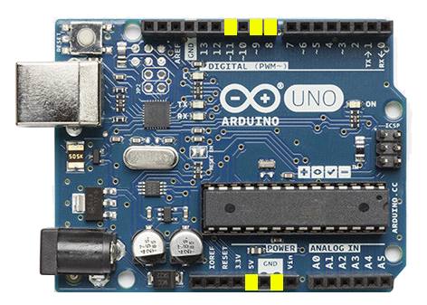
| Arduino connection | Function in this project | Builder check |
|---|---|---|
| 5 V | Powers the IR receiver and relay logic side | Measure close to 5 V between 5 V and GND before connecting the sensor |
| GND | Common reference for Arduino, relay logic, and IR receiver | All low-voltage grounds must be common |
| Digital pin 8 | Relay channel 1 command | Relay should click only for one direction command |
| Digital pin 9 | Relay channel 2 command | Relay should click only for the opposite direction command |
| Digital pin 11 | IR receiver signal input | Serial Monitor should show codes when remote buttons are pressed |
If you change pins in the wiring, update the sketch to match. A frequent mistake is moving the IR signal lead to a different Arduino pin during final assembly and forgetting that the software still listens on pin 11.
Relay Module Setup and Jumper Configuration
The relay module is used to reverse polarity to the actuator motor circuit. This is the same principle used by many simple DC motor direction controls: one polarity extends the actuator, and the opposite polarity retracts it. The Arduino energizes one relay channel for one direction and the other relay channel for the reverse direction.
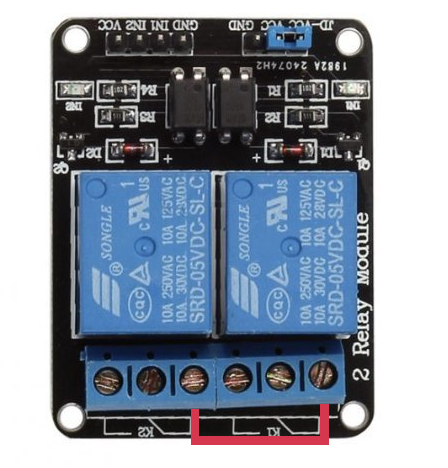
Initial Relay Configuration
The SainSmart board shown in the original build includes a jumper between JD-VCC and VCC. In this version, leave that jumper installed so the relay coils and relay logic share the Arduino 5 V supply. If you remove it, the relay coil side needs its own supply and the wiring method changes.
Creating the Polarity-Reversing Connections
Add the two jumper wires on the relay screw terminals as shown in the original build:
- Connect K1 position 1 to K2 position 1.
- Connect K1 position 3 to K2 position 3.
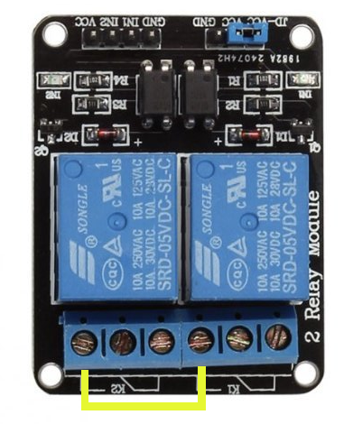
The software must interlock the relays so both channels cannot be active together. Do not rely only on good intentions while pressing buttons. Use code that first turns both relay outputs off, waits briefly if needed, and then energizes only the requested channel. For larger actuators or supplies with high available current, confirm the relay contact rating is suitable for the motor load. The guide Amps, Volts, Watts Guide for Linear Actuators is useful when checking basic electrical sizing.
Infrared Sensor Wiring and Connection
The infrared receiver lets the controller remain hidden while the small sensor is placed where the remote can see it. Most reliability problems with IR systems are not code problems; they are line-of-sight, pinout, or noise problems.
Preparing the Sensor Cable
The 18/5 cable contains more conductors than needed. Use three conductors for signal, ground, and 5 V. In the original build, blue is signal, green is ground, and white is 5 V. Strip only enough insulation to make a secure solder joint. Long bare leads near an IR receiver can touch when the cable is moved into the enclosure.
Soldering the Receiver
With the sensor lens facing you, the original wiring convention is:
- Left terminal: blue wire for signal output
- Middle terminal: green wire for ground
- Right terminal: white wire for 5 V
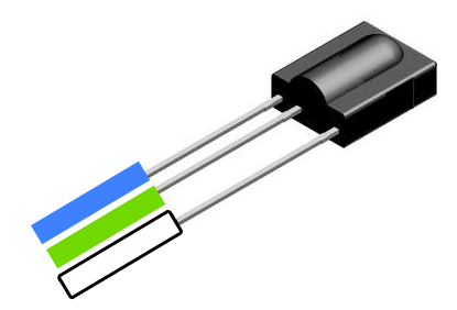
Important assumption: receiver pinouts are not universal. Before soldering, compare your receiver's datasheet or supplier drawing against this orientation. If 5 V and ground are reversed, the receiver may fail immediately. After soldering, add heat-shrink tubing or another insulation method so the leads cannot flex into each other.
Actuator Wiring Harness Modification
The original build modifies the actuator's wired control pendant so the relay board can perform the switching normally done by the hand controller. Work slowly here. Take a photo before removing any wire so you have a record of the original order.
Disassembling the Wired Remote Control
Remove the small screws from the back of the pendant housing and expose the circuit board. The pendant uses momentary switches to connect the actuator wires in the direction needed for extension or retraction. The relay module will duplicate that function electronically.
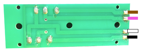
Identifying Wire Order
In the demonstration board, the wire order from left to right is black, white, purple, and brown. Treat that as an example from this build, not a universal color standard. If your harness uses different colors, preserve the positional order and label each conductor before desoldering.
Desoldering the Wires
Heat one solder joint at a time and gently pull the conductor free with small pliers. Avoid pulling before the solder is molten; torn pads or stretched strands make reassembly harder. If you have solder wick, use it to clean the pads and reduce the amount of heat required.
Connecting Wires to Relay Terminals
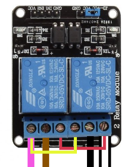
- White wire: K1 position 1
- Black wire: K1 position 2
- Brown wire: K2 position 2
- Purple wire: K2 position 3
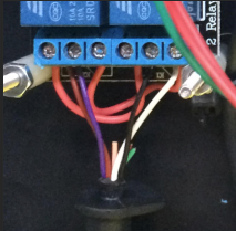
After tightening the terminals, tug each conductor lightly. If a wire slips out, strip and reinsert it. If the terminal is clamping insulation, the circuit may test intermittently on the bench and fail once installed behind the TV.
Breadboard Wiring and Power Distribution
The mini breadboard is used as a tidy distribution point. It keeps the 5 V, ground, and IR signal connections serviceable without twisting wires together inside the enclosure.
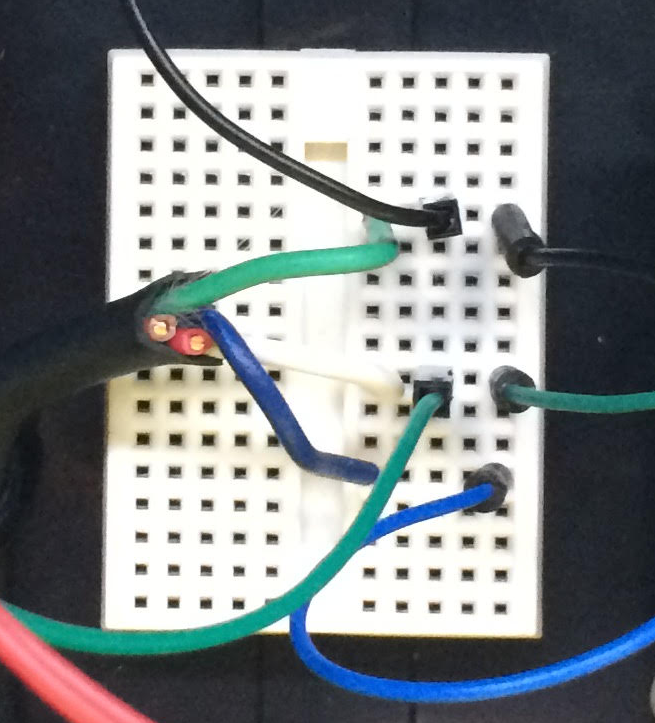
5 V Distribution
- Run a jumper from Arduino 5 V to an unused breadboard row.
- Connect the relay module VCC to that same row.
- Insert the white IR receiver wire into that same row.
Ground Distribution
- Run a jumper from Arduino GND to a different unused breadboard row.
- Connect relay module GND to that row.
- Insert the green IR receiver wire into that row.
IR Signal Connection
- Run a jumper from Arduino digital pin 11 to a third unused breadboard row.
- Insert the blue IR receiver wire into that row.
Before connecting actuator power, use the multimeter to confirm there is no continuity between the 5 V row and the ground row. Then confirm the sensor cable has continuity from each receiver pin to the correct breadboard row.
Arduino Programming and Software Configuration
The Arduino sketch must decode the TiVo remote command and control the relay outputs. At minimum, the code should include the IR library setup, the two recognized button codes, relay output definitions, an interlock routine, and a motion timeout. The timeout matters because an IR command can be repeated, missed, or accidentally held longer than intended.
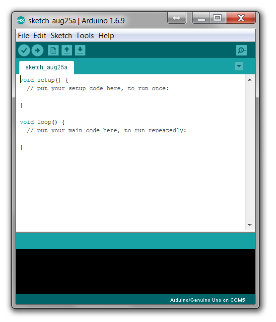
Installing the Arduino IDE
Install the Arduino IDE for your operating system and select the Arduino Uno board. Connect the board with the USB cable and choose the correct port under the Tools menu. If the board is not recognized, try a known data-capable USB cable; many charging cables do not include data lines.
Loading and Adapting the Code
The original project code was shared as a sketch that uses an IR remote library. If you recreate the project with a newer library version, expect some syntax differences. The engineering intent is unchanged: read the received code, compare it to the stored thumbs up or thumbs down value, and activate only the matching relay channel.
A practical commissioning method is to first upload a simple IR receive sketch and open Serial Monitor. Press the TiVo buttons you want to use and record the values displayed. Then paste those values into the control sketch. This avoids assuming your remote emits the same codes as the demonstration remote.
Library and Pin Notes
Older Arduino IDE installations included a RobotIRremote library conflict that could prevent compilation or point the receiver to the wrong pin. In the original instructions, the receive pin was corrected to digital pin 11. With current Arduino setups, the exact file path and library name may differ. If the sketch fails to compile, check for duplicate IR libraries and confirm the sketch's receive pin matches the physical wiring.
For projects that control more than one actuator or more than one direction pair, review FIRGELLI's 4-channel remote control guide for two actuators. It is a different control approach, but it helps explain how channel assignment affects actuator behavior.
System Testing and Functional Verification
Test the system on the bench before it is attached to the artwork. Keep fingers, wires, and loose tools clear of the actuator path. A linear actuator can develop enough force to damage brackets, cabinetry, or a TV frame if it is driven into a stop that was not designed for the load.
Initial Power-Up Test
- Power the Arduino by USB only. Confirm the relay board powers up and no relay is active by default.
- Open Serial Monitor and press the TiVo buttons. Confirm the Arduino receives codes.
- Command each direction and listen for one relay click at a time.
- Only after the logic behaves correctly, connect the actuator supply and actuator harness.
Motion Test
Point the TiVo remote toward the IR receiver from the expected seating position. Press thumbs up and verify the actuator moves in the intended direction. Press thumbs down and verify it reverses. If the directions are swapped, decide whether to correct the wiring or simply swap the button assignments in software. For a finished installation, software reassignment is often cleaner than reopening relay terminals.
Common Faults and Checks
- No serial IR code appears: Check receiver pinout, 5 V, ground, and line-of-sight. Also check that bright sunlight or another IR source is not saturating the receiver.
- Relays click but actuator does not move: Check actuator supply voltage, fuse or power supply protection, and the relay terminal wiring.
- Actuator moves only one direction: Inspect the second relay channel, its Arduino input pin, and the corresponding screw terminals.
- Actuator stops early: Check for mechanical binding, insufficient supply current, or the actuator reaching its internal limit switch.
- System works on the bench but not installed: Look for cable strain, poor sensor placement, panel misalignment, or guide rails that are not parallel.
Final Assembly in Project Enclosure
Once the bench test passes, mount the Arduino, relay board, and breadboard in the project box. Use nylon spacers so the boards cannot contact the enclosure or each other. Do not leave loose boards inside a cabinet; vibration and cable movement eventually create intermittent faults.
Preparing the Enclosure
Create separate openings for the USB cable, actuator harness, and IR receiver cable. If the IR receiver is inside the box, provide a clear window or opening with line-of-sight to the remote. In many hidden TV installations, it is better to mount only the small IR receiver outside the enclosure and hide it near the television frame or cabinet edge.
Strain Relief
Add cable ties inside the enclosure so pulling on an external cable does not load the solder joints or breadboard connections. This is especially important for the IR receiver cable because it may be routed through cabinetry before reaching the controller.
Integration Considerations for Hidden TV Systems
The electronics are only half of the project. The mechanical system determines whether the finished lift looks smooth, quiet, and intentional.
Stroke Length Selection
Measure the distance the artwork must travel to fully clear the viewable screen, then add clearance for the frame, brackets, and any trim. Example assumption: if the artwork must rise 24 inches to uncover the screen and you need 2 inches of extra clearance, select a stroke that provides at least 26 inches of travel. Do not select a stroke so long that the panel can collide with ceiling trim or internal cabinet stops.
Load and Force Margin
Weigh the moving assembly: artwork, frame, mounting plate, fasteners, and any attached guide hardware. Then size the actuator with a margin above that weight and account for friction from guides. If the panel is hinged or mounted at an angle, the force will not equal the panel weight; it changes with geometry. In that case, use a calculator rather than a rule of thumb. FIRGELLI's Actuator Mounting Angle Calculator is helpful when the actuator is not pushing in a straight, efficient line.
Guide Rails and Alignment
Large panels should not rely on the actuator alone to prevent twisting. Use parallel guides or slide rails so the panel moves vertically without racking. Check alignment by moving the panel through its full travel by hand where possible before attaching the actuator. If it binds by hand, the actuator will only hide the problem until something bends or loosens.
Actuator and Control Decision Table
| Design choice | Best fit | What to check before buying | Common mistake to avoid |
|---|---|---|---|
| Track actuator | Vertical panel or artwork lift where the moving carriage benefits from rail support | Stroke, load rating, available mounting space, and clearance behind the TV | Assuming the actuator can also act as the only guide for a wide flexible panel |
| Rod-style actuator | Hinged doors, linkages, or push/pull mechanisms with external guides | Mounting angle, force through the full travel, and bracket strength | Sizing from panel weight only and ignoring leverage |
| Arduino plus relay module | Custom IR commands, experimentation, and expandable logic | Relay current rating, code interlock, timeout behavior, and enclosure quality | Letting both relays energize at once |
| Dedicated remote control system | Simple installations where custom programming is not needed | Number of channels, voltage compatibility, and whether momentary or latching control is required | Buying too few channels for future expansion |
| Feedback actuator or position sensing | Systems needing repeatable intermediate positions or synchronized motion | Controller compatibility with the feedback signal | Expecting a standard two-wire actuator to report position |
System Expansion and Enhancement Options
After the basic TiVo-controlled lift works, the Arduino platform can be expanded. Useful additions include a physical wall switch, a current-sensing cutoff, a door-closed interlock, or a status LED hidden inside the cabinet. For very wide panels, consider whether two actuators are needed and whether they must be synchronized. Wiring two motors in parallel without thinking through load sharing can make one side lead the other, causing the panel to rack.
If your design uses multiple actuators or a nonstandard power arrangement, review the Parallel and Series Actuator Configuration Calculator before wiring. The calculator helps frame the electrical tradeoffs, but you should still follow the actuator and controller documentation for the final design.
Maintenance and Longevity
A hidden TV lift is usually cycled only a few times per day, so a clean installation should last a long time. The key is periodic inspection. Every 6 to 12 months, check the actuator mounts, panel fasteners, guide rail screws, cable strain relief, and relay enclosure. Listen for new scraping, clicking, or uneven motion. A change in sound is often the first sign of a loose bracket or misaligned guide.
Do not add grease or oil to exposed actuator parts unless the actuator documentation specifically calls for it. Unapproved lubricants can attract dust and create wear. Keep the electronics dry, ventilated, and accessible. If the controller is buried permanently behind trim with no service access, a simple relay replacement can become a major cabinet repair.
FAQ
Can I use a different TiVo remote or a universal remote?
Yes, if the remote sends infrared commands that the receiver and Arduino library can read. Capture the actual button codes with a test sketch and update the control sketch. Do not assume two remotes with similar button labels send the same codes.
Can the Arduino power the actuator directly?
No. The Arduino can power low-current logic components such as the IR receiver and relay input side. The actuator motor needs its own appropriately rated power supply. The relay contacts switch the actuator power circuit; the Arduino does not supply motor current.
What happens if someone keeps holding the remote button?
The safest code includes a timeout so the actuator stops after a defined maximum run time. The actuator may also have internal limit switches, but software timeout is still good practice because it protects against stuck buttons, repeated IR commands, and wiring mistakes during testing.
Do I need guide rails?
For a small, rigid, well-balanced panel, the actuator may appear to work without guides during a bench test. For a large artwork panel over a TV, guides are strongly recommended. They keep the panel square, reduce side load on the actuator, and make the motion look professional.
How do I choose the actuator stroke?
Measure the actual travel needed to clear the TV and frame, then add a small clearance allowance. Also confirm the retracted and extended lengths fit inside the wall or cabinet. Stroke is not the same as overall actuator length.
Why does the relay click but the actuator not move?
Most likely causes are no actuator power, incorrect relay terminal wiring, a loose screw terminal, or a supply that cannot provide the required current. Check voltage at the actuator side of the relay while a command is active.
Can I add voice control or smart-home control later?
Yes. The Arduino approach can be expanded with additional modules or replaced by a smart-home-capable controller. Keep the actuator power switching rules the same: correct voltage, sufficient current capacity, relay or driver interlock, and safe motion limits.
Conclusion
This TiVo remote actuator project shows how consumer electronics, Arduino logic, relay switching, and a FIRGELLI actuator can be combined into a practical hidden TV lift. The concept is simple, but the details matter: size the actuator from real loads, preserve correct polarity-reversing relay wiring, verify IR codes before final assembly, and build the mechanical guides so the panel cannot bind.
Once the core system is working, the same architecture can be adapted to many other automation tasks. Start with a safe bench test, document every wire, and make the finished controller serviceable. Those habits are what turn a clever prototype into a reliable installation.
Linear Actuator Force Calculator — Incline with Friction Linear Actuator Gear Reduction Calculator Linear Actuator Speed vs. Force Tradeoff Calculator Thermal Expansion Calculator — Linear Actuator Speed Calculator — Extension Time


