What Is Mechanical Advantage?
Mechanical advantage (MA) is the ratio of the output force a machine produces to the input force you apply. It tells you how much a tool, machine, or mechanism multiplies your effort. An MA greater than 1 means the machine amplifies force — you can move a heavy load with less effort. An MA less than 1 means the machine amplifies speed or distance instead.
The fundamental formula is:
MA = Output Force ÷ Input Force
Or equivalently, using the conservation of energy:
MA = Input Distance ÷ Output Distance
This second formula reveals the core trade-off in every mechanical advantage system: what you gain in force, you lose in distance (or speed), and vice versa. Energy is conserved — no machine creates energy from nothing. A lever that lets you lift 200 lbs with 50 lbs of effort (MA = 4) requires you to push your end four times farther than the load moves.
Ideal vs. Actual Mechanical Advantage
Ideal mechanical advantage (IMA) is calculated from the geometry of the machine alone — lever arm lengths, gear tooth counts, screw pitch — assuming zero friction. Actual mechanical advantage (AMA) is what you measure in the real world, where friction, material deformation, and other losses reduce the output. The ratio of AMA to IMA gives the machine's efficiency:
Efficiency = (AMA ÷ IMA) × 100%
A well-designed ball screw mechanism might achieve 90% efficiency, while a worm gear might be only 40-50% efficient — but that low efficiency is sometimes desirable because it makes the mechanism self-locking (the load can't back-drive the input), which is critical in lifting applications like linear actuators and jacks.
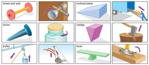
Three Types of Mechanical Advantage Systems
Every mechanical advantage mechanism falls into one of three categories based on what it amplifies:
- Force advantage — amplifies the input force to generate a larger output force (MA > 1). Used for lifting heavy objects, pressing, clamping. Examples: second-class levers, compound pulleys, hydraulic presses, worm gears.
- Distance advantage — amplifies the input displacement to achieve greater output range or reach (MA < 1 for force, but output moves farther). Used for extending reach, covering large distances. Examples: third-class levers, inclined planes, gear step-up ratios.
- Speed advantage — amplifies the input speed so the output moves faster (MA < 1 for force). Used for rapid movement, high-speed operations. Examples: gear step-up ratios, third-class levers, certain pulley configurations.
All Mechanical Advantage Mechanisms at a Glance
The table below summarizes every major mechanical advantage mechanism, its MA formula, what it's best for, and its key trade-off.
| Mechanism | MA Formula | Advantage Type | Typical MA Range | Key Trade-off |
|---|---|---|---|---|
| 1st-class lever | Effort arm / Load arm | Force, distance, or speed | 0.1 – 10+ | Depends on fulcrum position |
| 2nd-class lever | Effort arm / Load arm | Force (always > 1) | 1.5 – 10 | Reduced speed and distance |
| 3rd-class lever | Effort arm / Load arm | Speed/distance (always < 1) | 0.1 – 0.9 | Requires more force than load |
| Fixed pulley | 1 (direction change only) | Direction change | 1 | No force advantage |
| Movable pulley | 2 | Force | 2 | Pull twice the rope length |
| Compound pulley | Number of supporting ropes | Force | 2 – 10+ | More rope, more friction |
| Spur gears | Driven teeth / Driving teeth | Force or speed | 0.2 – 10 | Speed vs. torque |
| Worm gear | Worm wheel teeth / Worm starts | Force (high ratio) | 10 – 100+ | Very slow, high friction |
| Hydraulic system | Output piston area / Input piston area | Force | 2 – 1000+ | Fluid volume, slow speed |
| Inclined plane | Slope length / Height | Force | 1.5 – 20 | Longer distance traveled |
| Wedge | Length / Thickness | Force (splitting) | 2 – 20 | Friction, wear |
| Screw | π × diameter / pitch | Force (very high) | 5 – 200+ | Very slow linear speed |
Levers: Force, Balance, and Leverage
Levers are the most fundamental mechanical advantage mechanism. A lever consists of a rigid bar pivoting around a fixed point (the fulcrum). By changing the position of the fulcrum relative to the input force (effort) and output force (load), levers can amplify force, speed, or distance.
The lever equation is:
Effort × Effort Arm = Load × Load Arm
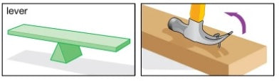
First-Class Levers
In a first-class lever, the fulcrum sits between the effort and the load. Depending on where the fulcrum is placed, the MA can be greater than 1 (force advantage), equal to 1 (balanced), or less than 1 (speed/distance advantage). Examples include seesaws, crowbars, scissors, and pliers.
Try our free First-Class Lever Calculator
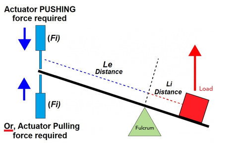
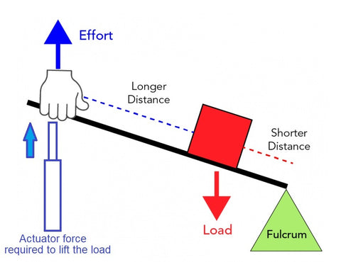
Second-Class Levers
In a second-class lever, the load sits between the fulcrum and the effort. The effort arm is always longer than the load arm, giving an MA that is always greater than 1. This makes second-class levers ideal for lifting heavy loads with less force. Examples include wheelbarrows, nutcrackers, bottle openers, and actuator-powered hatches and lids.
Try our free Second-Class Lever Calculator
Third-Class Levers
In a third-class lever, the effort is applied between the fulcrum and the load. The effort arm is always shorter than the load arm, giving an MA always less than 1. Third-class levers require more force than the load weighs, but in exchange the load moves faster and farther than the effort point. Examples include fishing rods, tweezers, the human forearm, and baseball bats.
Try our free Third-Class Lever Calculator

Lever Comparison
| Feature | First-Class | Second-Class | Third-Class |
|---|---|---|---|
| Arrangement | Effort — Fulcrum — Load | Fulcrum — Load — Effort | Fulcrum — Effort — Load |
| MA | Can be >1, =1, or <1 | Always > 1 | Always < 1 |
| Best for | Versatile applications | Heavy lifting | Fast/long-range motion |
| Examples | Seesaw, crowbar, scissors | Wheelbarrow, nutcracker | Fishing rod, tweezers |
| Calculator | 1st-Class Calc | 2nd-Class Calc | 3rd-Class Calc |
For more on how levers combine to form complete mechanisms, see our Basics of Linkages guide and our Compound Lever Calculator for cascading multiple levers in series.
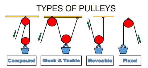
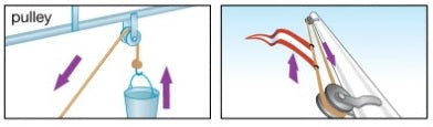
Pulleys: Load Distribution and Direction Change
Pulleys use grooved wheels and ropes or cables to change the direction of applied force and distribute loads across multiple rope segments. The mechanical advantage of a pulley system depends on how many rope segments support the load.
Fixed Pulleys
A fixed pulley is anchored to a structure. It changes the direction of force (letting you pull down to lift up) but provides no mechanical advantage — the effort equals the load. Fixed pulleys are used where changing force direction is more convenient than adding MA, such as flagpole halyards and well buckets.
Movable Pulleys
A movable pulley is attached to the load itself, with one end of the rope fixed. This splits the load across two rope segments, providing an MA of 2 — you need only half the force to lift the load. The trade-off: you must pull twice as much rope to lift the load the same height. Movable pulleys are used in cranes, hoists, and block-and-tackle systems.
Compound Pulleys (Block and Tackle)
Compound pulleys combine fixed and movable pulleys to achieve higher MA. The mechanical advantage equals the number of rope segments supporting the load. A 4-pulley block and tackle has an MA of 4 — a 100 lb load requires only 25 lbs of effort, but you pull 4 feet of rope for every 1 foot the load rises.
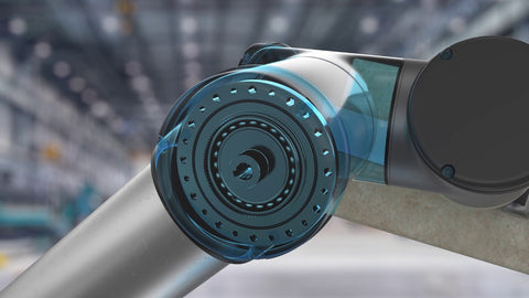
Above: how a telescopic actuator uses pulleys and a leadscrew drive to multiply stroke length
Gears: Torque, Speed, and Precision
Gears are toothed wheels that mesh together to transmit torque and motion between rotating shafts. The mechanical advantage of a gear pair is determined by the gear ratio:
Gear Ratio = Driven Gear Teeth ÷ Driving Gear Teeth
A gear ratio greater than 1 increases torque (force advantage) while reducing speed. A ratio less than 1 increases speed while reducing torque.
Spur Gears
Spur gears have straight teeth and transmit motion between parallel shafts. They are the most common gear type, offering precise speed and torque control. A small driving gear (pinion) meshing with a larger driven gear creates a force advantage — used in gear reduction systems for linear actuators, power tools, and industrial machinery.
Helical Gears
Helical gears have angled teeth arranged in a helix pattern, providing smoother and quieter operation than spur gears. The angled teeth engage gradually, distributing the load over a larger contact area. Helical gears are used in automotive transmissions, high-speed machinery, and applications where noise reduction matters.
Worm Gears
Worm gears consist of a threaded shaft (worm) meshing with a toothed wheel (worm gear). They provide very high gear ratios (often 20:1 to 100:1 in a single stage) and are self-locking — the load cannot back-drive the worm. This makes worm gears ideal for lifting mechanisms, conveyor drives, and the internal gear trains of electric linear actuators where the actuator must hold position under load without a brake.
Hydraulic Systems
Hydraulic systems use incompressible fluid (typically oil) to transmit and amplify force. They operate on Pascal's principle: pressure applied to a confined fluid is transmitted equally in all directions. The mechanical advantage of a hydraulic system is:
MA = Output Piston Area ÷ Input Piston Area
A small piston pushing fluid into a large piston creates enormous force multiplication. Hydraulic systems can achieve MA values of 100:1 or more, making them the highest force-density mechanical advantage mechanism available.
Hydraulic Pistons and Cylinders
Hydraulic cylinders contain a piston that moves linearly when pressurized fluid enters the chamber. They are used in construction equipment (excavators, bulldozers), automotive braking systems, aircraft landing gear, and industrial presses. Hydraulic cylinders deliver very high forces but require a pump, reservoir, valves, and fluid lines — making them more complex and maintenance-intensive than electric alternatives.
Hydraulic vs. Electric Actuators
For many applications that previously required hydraulic cylinders, electric linear actuators now provide a simpler, cleaner, and more controllable alternative. Electric actuators use an internal screw mechanism (another form of mechanical advantage) to convert motor rotation into linear force. They require only an electrical connection — no pumps, hoses, fluid, or maintenance. For a detailed comparison, see our Hydraulic vs. Electric Actuators guide.
Inclined Planes, Wedges, and Screws
These three mechanisms are all variations of the same principle: spreading a vertical force over a longer, angled path to reduce the effort required at any given point.
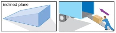
Inclined Planes (Ramps)
An inclined plane reduces the force required to raise an object by increasing the distance traveled. Instead of lifting straight up, you push the object along a slope. The MA equals the slope length divided by the vertical height:
MA = Slope Length ÷ Height
A 10-foot ramp rising 2 feet has an MA of 5 — you need only one-fifth the force of lifting the object straight up, but you push it five times farther. Shallower angles give higher MA but require more distance. Ramps, loading docks, and wheelchair ramps are all inclined planes.
Wedges
A wedge is a portable inclined plane that converts a force applied to its blunt end into splitting force perpendicular to its faces. The MA of a wedge equals its length divided by its thickness. Axes, knives, chisels, door stops, and zipper teeth are all wedges. The thinner and longer the wedge, the greater the splitting force — but the more distance it must be driven.
Screws
A screw is an inclined plane wrapped around a cylinder. Each revolution of the screw advances the load by one pitch (the distance between adjacent threads). The MA of a screw is:
MA = π × Screw Diameter ÷ Pitch
Screws provide extremely high mechanical advantage — a fine-pitch screw can produce MAs of 100:1 or more. This makes screws the operating principle inside most electric linear actuators, where a motor rotates a lead screw or acme screw and a nut converts that rotation into precise, high-force linear motion.

Force, Distance, and Speed Advantage Systems Compared
Every mechanical advantage mechanism involves a trade-off. The table below shows which mechanisms excel at each type of advantage and what you sacrifice in return.
| Advantage Type | Best Mechanisms | You Gain | You Sacrifice | Applications |
|---|---|---|---|---|
| Force | 2nd-class levers, compound pulleys, hydraulics, worm gears, screws | Higher output force | Speed and distance | Lifting, pressing, clamping, actuator-powered hatches |
| Distance | 3rd-class levers, inclined planes, gear step-up ratios | Greater range of motion | Force (need more input effort) | Ramps, extended reach, conveyor systems |
| Speed | 3rd-class levers, gear step-up ratios, fixed pulleys | Faster output movement | Force (need more input effort) | Robotics, sports equipment, high-speed machinery |
Mechanical Advantage in Electric Linear Actuators
Electric linear actuators use mechanical advantage at multiple levels to convert a small motor's rotary output into powerful, precise linear motion.
Internal Mechanical Advantage
Gear reduction between the motor and the lead screw multiplies the motor's torque. A higher gear ratio produces more force but slower speed. FIRGELLI actuators use precision gear trains optimized for the force-speed balance required by each model.
Screw pitch determines the force advantage of the lead screw itself. A finer pitch (fewer threads per inch) produces higher force but slower linear speed. A coarser pitch gives faster speed but lower force. The screw mechanism also provides self-locking — the actuator holds its position under load without consuming power, which is critical for lifting applications.
Above: a 3-stage telescopic linear actuator using nested screw mechanisms for extended stroke length
External Mechanical Advantage: Linkages
When an actuator is mounted in a linkage system, the linkage geometry adds another layer of mechanical advantage. Common configurations include:
- Second-class lever (lid/hatch) — amplifies actuator force for heavy lids. Use our Lid and Hatch Calculator.
- Bell-crank redirect — redirects actuator force 90° for tight spaces.
- Parallel-motion linkage — keeps platforms level in scissor lifts.
- Compound lever — cascades multiple levers. See our Compound Lever Calculator.
A well-designed linkage lets you use a smaller, less expensive actuator to handle a heavier load. The choice of linkage directly affects force requirement, stroke length, and mounting geometry.
Stroke Advantage: Telescopic Actuators
Standard actuators have a retracted length roughly equal to their stroke plus body length. Telescopic actuators use nested sections that extend within each other, providing a much longer stroke in a compact retracted form factor. This is a distance advantage — the actuator reaches farther while maintaining a small footprint. FIRGELLI's telescopic column lifts use this principle for sit-stand desks, TV lifts, and industrial positioning systems.
Real-World Applications by Industry
Mechanical advantage mechanisms are everywhere. Here are key applications across major industries:
Industrial and Manufacturing
Conveyor systems use pulley-based belt drives to transport heavy loads. Cranes and hoists employ compound pulleys and hydraulic cylinders for lifting. Assembly line robots use gear trains and lever systems for precise positioning. Stamping presses use lever and hydraulic mechanisms to generate tons of forming force.
Construction and Engineering
Tower cranes use pulley systems to lift materials to great heights. Excavators and bulldozers rely on hydraulic cylinders (force advantage) to dig and push. Adjustable scaffolding uses screw mechanisms to raise and lower platforms.

Automotive
Braking systems use lever mechanisms to convert pedal force into braking force. Suspension systems use linkages and springs to absorb shocks. Power steering uses hydraulic or electric assist to reduce steering effort. Automatic transmissions use planetary gear sets to provide multiple gear ratios.
Aerospace
Aircraft control surfaces (flaps, ailerons, elevators) use lever and linkage mechanisms controlled by hydraulic or electric actuators. Landing gear uses hydraulic cylinders for deployment and retraction. Thrust reversers use linkage systems to redirect engine exhaust for braking after landing.
Biomechanics and Human Body
The human skeletal system is a lever system — bones are levers, joints are fulcrums, and muscles provide effort. The forearm is a third-class lever (bicep effort between elbow fulcrum and hand load) optimized for speed and range of motion. Prosthetics and exoskeletons use mechanical advantage mechanisms to restore or augment human capabilities.
Robotics and Automation
Robots use gear trains, screw mechanisms, and linkages to achieve precise, high-force, high-speed motion. Humanoid robots are increasingly replacing hydraulic actuators with compact electric actuators that use screw mechanisms and harmonic drives for high torque density in a small package.


Related Engineering Calculators and Guides
Use these free tools and references to design mechanisms with mechanical advantage:
- First-Class Lever Calculator — calculate force and stroke for first-class lever mechanisms
- Second-Class Lever Calculator — force and stroke for lids, hatches, and wheelbarrow-type mechanisms
- Third-Class Lever Calculator — force and stroke for speed amplification mechanisms
- Second-Class Lever Angled Calculator — when the actuator pushes at an angle
- Compound Lever Calculator — cascaded levers for high mechanical advantage
- Lid and Hatch Actuator Calculator — interactive tool for hatch, lid, and pop-top roof actuator sizing
- Scissor Lift Calculator — force and stroke for scissor-lift mechanisms
- Full Calculator Suite — all FIRGELLI engineering calculators in one place
- Basics of Linkages — fundamentals of levers, joints, and linkage design
- Types of Linkages Guide — four-bar inversions, straight-line generators, Grashof's law
- Types of Motion Explained — linear, rotary, reciprocating, and oscillating motion
- IP Ratings Guide — choosing actuators for outdoor and washdown environments
- Humanoid Robot Actuators — the shift from hydraulic to electric actuation
- AWG Wire Gauge Chart — wire sizing for actuator power circuits
- Polarity Reversal Guide — how to reverse actuator direction with DC motor wiring
Frequently Asked Questions About Mechanical Advantage
What is mechanical advantage?
Mechanical advantage (MA) is the ratio of the output force a machine produces to the input force applied. An MA greater than 1 means the machine amplifies force. An MA less than 1 means it amplifies speed or distance instead. The formula is MA = Output Force / Input Force.
What are the three types of mechanical advantage systems?
The three types are force advantage (output force greater than input), distance advantage (output distance greater than input), and speed advantage (output speed greater than input). Every system trades off between these three — increasing one always decreases at least one of the others.
How do you calculate the mechanical advantage of a lever?
MA = Effort Arm Length ÷ Load Arm Length. First-class levers can have MA above or below 1 depending on fulcrum position. Second-class levers always have MA > 1 (force multipliers). Third-class levers always have MA < 1 (speed multipliers). Use our free lever calculators to compute exact values.
What is the difference between ideal and actual mechanical advantage?
Ideal MA (IMA) is calculated from geometry alone, assuming no friction. Actual MA (AMA) is measured from real-world forces, which includes friction and other losses. AMA is always less than IMA. Efficiency = (AMA / IMA) × 100%.
How does a pulley system provide mechanical advantage?
A single fixed pulley changes force direction but gives no MA. A movable pulley gives MA of 2. Compound systems (block and tackle) multiply further — the MA equals the number of rope segments supporting the load. A 4-rope system needs only 25% of the load weight as effort, but you pull 4 times the rope length.
How do gears provide mechanical advantage?
The gear ratio equals driven gear teeth divided by driving gear teeth. Ratios > 1 increase torque (force advantage) while reducing speed. Ratios < 1 increase speed while reducing torque. Worm gears provide very high ratios (20:1 to 100:1) and are self-locking, making them ideal for linear actuators and lifting applications.
How does mechanical advantage apply to electric linear actuators?
Electric actuators use MA at multiple levels. Internally, gear reduction multiplies motor torque, and the lead screw pitch determines force advantage (finer pitch = more force, slower speed). Externally, mounting an actuator in a linkage system can further amplify or redirect force. FIRGELLI provides free lever calculators for sizing actuators in linkage-based installations.


