The Critical Role of Linear Actuator Mounting Brackets
When engineers and DIY enthusiasts design motion control systems, they typically focus considerable attention on selecting the right linear actuator — calculating force requirements, stroke length, speed, and voltage. Yet the seemingly mundane decision of which mounting brackets to use often receives far less consideration, sometimes relegated to an afterthought or a last-minute hardware store run.
🎥 Video — Common Linear Actuators Mounting Brackets
This oversight can be costly. The mounting bracket is the critical mechanical interface between your actuator and your application. It determines whether your actuator can pivot freely or must remain stationary, affects load distribution and alignment, and directly impacts the longevity and reliability of your entire system. A poorly chosen mounting bracket can introduce binding, premature wear, or catastrophic failure — even when the actuator itself is perfectly specified.
This comprehensive guide examines the complete range of linear actuator mounting hardware available from FIRGELLI Automations, from the ubiquitous clevis brackets to specialized rod-end mounts and body clamps. We'll explore the engineering principles behind each design, their load capacities, ideal applications, and compatibility with specific actuator series. Whether you're building a custom TV lift, automating a marine hatch, or designing an industrial positioning system, understanding mounting bracket selection will significantly improve your project's success.
Clevis Mounting Brackets: Maximum Articulation for Dynamic Applications
Clevis mounting brackets represent the most versatile and commonly deployed mounting solution for linear actuators. The clevis design — featuring a U-shaped yoke with aligned holes for a pin connection — has been used in mechanical systems for centuries because it elegantly solves a fundamental challenge: allowing rotational freedom while transmitting substantial forces.


Engineering Principles of Clevis Connections
FIRGELLI's clevis brackets attach to the mounting holes at either end of compatible actuators using a through-pin secured with a cotter pin or R-clip. This simple mechanical joint permits over 180 degrees of rotation, allowing the actuator to pivot freely as it extends and retracts. This articulation is essential in any application where the mounting points move in relation to each other during actuation.
The pin-and-clevis connection distributes forces across a relatively large bearing surface area, which is why properly designed clevis brackets can handle substantial loads. FIRGELLI's clevis mounting brackets are engineered to withstand forces exceeding 1,000 pounds, with heavy-duty variants rated for up to 3,000 lbs. This makes them suitable not just for hobby projects but for demanding automotive, marine, and industrial applications.
FIRGELLI Clevis Bracket Model Range
FIRGELLI offers an extensive selection of clevis brackets designed for specific actuator series:
- MB1: The workhorse bracket compatible with Classic Rod, Feedback Rod actuators, Utility units, and Mini-Track actuators. This is the most universally applicable clevis bracket in the FIRGELLI lineup.
- MB1-P: Specifically engineered for P-Series actuators and Utility units, including Optical Sensor and Adjustable Limit variants. The "-P" designation indicates compatibility with the premium actuator line.
- MB2: Features a unique profile designed to fit into the mounting notch of Sleek Rod Tubular actuators and Utility actuators.
- MB3 and MB3U: Heavy-duty brackets made for L-style Heavy Duty actuators. These robust brackets can be mounted on either end of the actuator and are built for high-load applications.
- MB8: Designed specifically for High Speed actuator units, sold in pairs with one set per actuator.
- MB14: Engineered for Mini-Bullet actuators, including the Bullet .23 Cal series. Note that these will not fit Micro actuators.
- MB17: Purpose-built for Super Duty actuators, fitting either clevis end of these high-force units.
- MB18: Specialized bracket for specific application requirements.
- MB35: Designed for Bullet Series 35 units, supplied in pairs.
- MB50U: Heavy-duty clevis bracket for Bullet .50 caliber actuators, engineered for substantial load capacity.
Ideal Applications for Clevis Brackets
Clevis mounting brackets excel in hinge-style applications where the actuator must accommodate changing angles during operation. Common implementations include:
- Hatches and access doors: Marine hatches, RV roof vents, and truck tonneau covers benefit from the clevis bracket's ability to maintain smooth operation as angles change.
- Solar panel tracking systems: Single or dual-axis solar trackers require actuators that can pivot freely while positioning panels throughout the day.
- Adjustable furniture: Reclining chairs, adjustable beds, and ergonomic workstations use clevis-mounted actuators to provide smooth, reliable motion.
- Automotive applications: From trunk lifts to convertible roof mechanisms, clevis brackets handle the complex motion paths required in vehicle automation.
- Agricultural equipment: Implement positioning, hopper doors, and access panels in farm machinery rely on clevis connections for durability in harsh environments.
The elongated mounting holes featured on most FIRGELLI clevis brackets provide an additional practical advantage: they allow for installation tolerance and adjustment. This feature simplifies alignment during installation and can compensate for minor fabrication variations in custom projects.
Static Mounting Brackets: Body Clamps for Fixed-Orientation Applications
While clevis brackets provide articulation, many applications require the actuator body to remain in a fixed orientation throughout its stroke. This is where static mounting brackets — often called body clamps — become essential. These brackets secure to the cylindrical body of the actuator rather than the end mounting points, preventing rotation while allowing the rod to extend and retract.

Body Clamp Engineering and Installation
FIRGELLI's static mounting brackets feature a clamping collar design that slides over the actuator body and secures with two bolts. This simple yet effective mechanism provides several engineering advantages. The clamping force distributes evenly around the actuator circumference, avoiding stress concentrations. The two-bolt design resists rotational forces that might otherwise cause the bracket to shift under load. Installation is straightforward — simply slide the bracket to the desired position and tighten the mounting bolts.
Unlike clevis brackets that attach at the actuator ends, body clamps can typically be positioned anywhere along the actuator body length. This flexibility allows designers to optimize lever arms, clear obstructions, or position the actuator for best mechanical advantage in their specific application.
FIRGELLI Static Bracket Model Range
FIRGELLI manufactures several distinct families of static mounting brackets:
Standard Static Mount Brackets
- MB6: The standard body clamp designed for Classic Rod and Feedback Rod actuators. These aluminum brackets are robust enough for marine and automotive applications. Installation may require some force to ensure a tight fit over the actuator body.
- MB6-P: Engineered specifically for the rod body of P-Series, P-Series High Force, and Optical Sensor actuators. Note that these brackets are not compatible with Adjustable-Limit Switch variants due to body diameter differences.
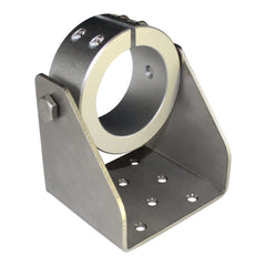
- MB20: A specialized body clamp bracket for Super Duty actuators, featuring a unique flush-mounting flange design perfect for mounting actuators directly against a surface.
Hanging-Style Body Clamps


Some applications require suspending the actuator rather than mounting it to a flat base. FIRGELLI's hanging-style brackets address this need:
- MB36C: Designed for Bullet .36 caliber actuators, this clamp-style bracket eliminates the flat mounting base, allowing the actuator to hang from a structural member or frame.
- MB21: A hanging bracket variant for Super Duty actuators, providing suspended mounting options for high-force applications.
- MB50C: The heavy-duty hanging clamp for Bullet .50 actuators, engineered to support substantial loads in suspended configurations.
Donut-Style Pivot Mounts


FIRGELLI's donut-style mounting brackets represent a hybrid approach, combining body mounting with pivot capability:
- MB36: Exclusively designed for Bullet .36 caliber actuators, this circular mounting bracket slides over the actuator body and secures with two bolts. Unlike standard static mounts, the MB36 allows the actuator to pivot, providing the articulation benefits of clevis brackets with the flexible mounting position of body clamps.
- MB50: The larger variant engineered for Bullet .50 actuators, offering the same body-mount-with-pivot functionality for higher force applications.
These donut-style brackets are particularly valuable in space-constrained applications or when mounting point geometry doesn't align with standard clevis mounting holes.

Applications Best Suited for Static Mounting
Static mounting brackets excel in applications requiring linear motion without actuator rotation:
- Drawer and cabinet systems: Motorized drawer slides benefit from body-clamped actuators that prevent twisting during operation.
- Vertical lift mechanisms: Pop-up TV lifts, monitor lifts, and platform elevators require actuators to maintain precise vertical orientation throughout travel.
- Linear positioning stages: CNC routers, 3D printers, and automated assembly equipment need actuators that move along fixed axes without rotation.
- Sliding door operators: Automated barn doors, pocket doors, and industrial bay doors use body-clamped actuators to maintain alignment with slide rails or tracks.
- Inspection and scanning systems: Camera positioning systems and automated inspection rigs require rigid actuator mounting to maintain optical alignment.
Most FIRGELLI static mounting brackets are manufactured from aircraft-grade aluminum, providing an excellent strength-to-weight ratio while resisting corrosion in marine and automotive environments. This makes them suitable for demanding applications in yachts, RVs, and commercial vehicles where weight matters and environmental exposure is harsh.
MB10 Rod-End Mounting Bracket: Specialized Side-Mount Solution

The MB10 Rod-End Mounting Bracket occupies a unique niche in FIRGELLI's mounting hardware lineup. Rather than attaching to the actuator body or end mounting holes, this specialized bracket fixes directly onto the extending rod itself, creating a rigid mechanical connection at the rod terminus.
MB10 Design and Engineering
The MB10 features a solid aluminum block with five threaded mounting holes strategically positioned across three surfaces. Four smaller tapped holes on the side faces provide mounting options perpendicular to the rod axis, while one large M10 mounting hole aligns coaxially with the actuator rod. This multi-plane mounting capability offers exceptional installation flexibility.
The bracket's compatibility span is impressive — it works with Classic Rod, Feedback Rod actuators, P-Series actuators (including Optical Sensor variants), Super Duty units, and Mini Linear Actuators. This broad compatibility makes the MB10 a versatile solution for engineers working with multiple actuator types.
When to Specify the MB10
The MB10 solves specific mounting challenges that other brackets cannot address:
- Side-mount applications without tracks: When space constraints prevent using a track actuator but side mounting is required, the MB10 provides a rigid connection point.
- Custom mechanical linkages: The multiple mounting holes enable direct attachment to custom brackets, linkages, or mechanical assemblies.
- Compact installations: The MB10's low profile can fit in tight spaces where clevis brackets would interfere with adjacent components.
- Multi-axis assemblies: Robotics and automation systems that require orthogonal mounting planes benefit from the MB10's three-sided hole pattern.
- Retrofit projects: When adapting an actuator to existing machinery, the MB10's flexibility often provides a mounting solution without requiring extensive fabrication.
Premium Base Mounting Bracket: Column Lift Conversion [Discontinued]


While no longer in active production, the Premium Base Mounting Bracket represented an innovative approach to actuator mounting that's worth understanding for those maintaining existing systems or considering DIY alternatives.
Column Lift Configuration
This specialized bracket transformed compatible P-Series and Optical Feedback Linear Actuators (up to 200 lbs force) into column-style lifts. Installation required removing the actuator's rear endplate and replacing it with the Premium Base Mounting Bracket, effectively converting the actuator's back end into a mounting base.
This configuration was particularly valuable for vertical installations, creating a compact alternative to full column lifts. The bracket enabled these actuators to function effectively in pop-up drawer systems, custom TV lifts, and other vertical lift applications where space constraints made traditional lifting columns impractical.
Modern Alternatives
For engineers seeking similar functionality in new designs, several approaches can achieve comparable results:
- Use dedicated column lift products for vertical lifting applications requiring substantial stroke and load capacity.
- Combine static body clamp brackets (MB6 or MB6-P) with clevis end brackets to create pseudo-column configurations suitable for lighter loads.
- Design custom base plates that attach to existing clevis mounting holes, creating application-specific column-style mounts.
- Consider Bullet actuator series with MB36 or MB50 donut-style mounts for compact vertical installations.
Comprehensive Bracket Selection Guide
Selecting the correct mounting bracket requires understanding both your actuator model and your application requirements. This section provides two complementary approaches: selection by bracket type and selection by actuator model.
Bracket-First Selection Guide
If you know which bracket you need, here's the compatibility breakdown:
- MB1: Compatible with Classic Rod, Feedback Rod actuators, Utility units, and both ends of Mini-Track actuators. The most versatile clevis option.
- MB1-P: Works with all P-Series actuators, Utility units, Optical Sensor variants, and Adjustable Limit Switch units.
- MB2: Specifically designed for the mounting notch of Sleek Rod Tubular actuators and Utility actuators.
- MB3 and MB3U: Heavy-duty clevis brackets for L-style Heavy Duty actuators, fitting either end.
- MB5: Required kit for Heavy-Duty Track actuators (one kit per actuator).
- MB6: Body clamp for Classic Rod and Feedback Rod actuators. May require firm installation force for proper fit.
- MB6-P: Body clamp for P-Series, P-Series High Force, and Optical Sensor actuators. Not compatible with Adjustable-Limit Switch units.
- MB8: Clevis brackets for High Speed actuators, supplied in pairs (one set per actuator).
- MB9: Mini L-brackets included with Mini-Track actuators (one set per unit).
- MB10: Universal rod-end bracket fitting Classic, P-Series, Feedback, Optical Sensor, and Adjustable Limit Switch actuators.
- MB14: Clevis brackets for Mini-Bullet and Bullet .23 Cal actuators (not compatible with Micro actuators).
- MB17: Heavy-duty clevis for Super Duty actuators, fits either end.
- MB20 & MB21: Body clamp brackets specifically for Super Duty actuators with different mounting configurations.
- MB35: Designed for Bullet Series 35 units, supplied in pairs.
- MB36, MB36C, MB36SM: Various mounting options for Bullet .36 Cal actuators.
- MB50, MB50C, MB50U: Mounting bracket family for Bullet .50 actuators with different configuration options.
Actuator-First Selection Guide
If you're starting with a specific actuator model, here's your bracket compatibility:
- Classic Actuators: MB1 (clevis), MB6 (body clamp), MB10 (rod-end)
- Feedback Rod Actuators: MB1 (clevis), MB6 (body clamp), MB10 (rod-end)
- P-Series Actuators: MB1-P (clevis), MB6-P (body clamp), MB10 (rod-end), MB-PB (base mount). Note: P-Series High Force units not compatible with MB-PB.
- Optical Sensor Actuators: MB1-P (clevis), MB6-P (body clamp), MB10 (rod-end), FA-OS-IMD3 (column mount variant). Note: 400# force units incompatible with FA-OS-IMD3.
- Adjustable Limit Actuators: MB1-P (clevis), MB10 (rod-end), MB-PB (base mount). Cannot use MB6-P body clamp.
- Super Duty Actuators: MB17 (clevis), MB20 & MB21 (body clamps)
- Utility Actuators: MB1, MB1-P, or MB2 brackets depending on specific model and mounting requirements
- Heavy Duty and Deluxe Actuators: MB3 and MB3U (including IP66-rated models)
- Heavy-Duty Track Actuators: MB5 kit (one per unit)
- Mini-Track Actuators: MB9 L-brackets (included with actuators) plus MB1 clevis holes at ends for additional mounting options
- Mini Linear Actuators: MB1 brackets
- Bullet .23 Cal and Mini-Bullet Actuators: MB14 brackets (supplied in pairs)
- Bullet .36 Cal (BH36): MB36, MB36C, or MB36SM (fitted to units)
- Bullet .50 (BH50): MB50U, MB50C, or MB50 brackets
- Bullet Series 35: MB35 brackets (supplied in pairs)
- Industrial Heavy Duty Units: Oversized clevis holes; MB3U and MB50U can be used but will not provide a tight fit
Key Selection Criteria Beyond Compatibility
While compatibility is essential, optimal bracket selection also considers:
- Load direction and magnitude: Ensure bracket force ratings exceed your application's maximum loads with appropriate safety factor (typically 2:1 minimum).
- Motion requirements: Does your application require articulation (clevis) or fixed orientation (body clamp)?
- Installation constraints: Space limitations, access for tools, and alignment tolerances affect bracket choice.
- Environmental factors: Aluminum brackets resist corrosion in marine environments; consider protective coatings for harsh industrial settings.
- Maintenance access: Some brackets facilitate easier actuator removal for service than others.
- Aesthetic considerations: Visible installations may benefit from lower-profile brackets or specific finishes.
Installation Best Practices and Common Pitfalls
Proper bracket installation significantly impacts actuator performance, longevity, and safety. These guidelines help ensure reliable operation:
Critical Alignment Considerations
Misalignment is the leading cause of premature actuator failure. When both ends of an actuator are mounted, the mounting points must align precisely along the actuator's axis of travel. Even minor misalignment creates side loads that bind the actuator, increase current draw, generate heat, and wear components prematurely.
For clevis-mounted actuators, ensure the pivot pins are parallel to each other and perpendicular to the actuator's axis of travel. The clevis bracket's ability to pivot cannot compensate for poor initial alignment — it's designed to accommodate motion during operation, not construction errors.
Body clamp brackets must be installed perpendicular to the actuator axis. Use a square or level during installation, and verify alignment before fully tightening mounting bolts. The elongated mounting holes on many FIRGELLI brackets provide adjustment range, but they're meant for fine-tuning, not correcting major alignment errors.
Fastener Selection and Torque Specifications
Always use appropriate grade fasteners for your application's loads. For most automotive and industrial applications, Grade 5 or Grade 8 bolts (SAE) or 8.8 or 10.9 metric bolts provide adequate strength. Marine applications benefit from stainless steel fasteners to resist corrosion, though care must be taken to avoid galling during installation.
Apply threadlocker (such as Loctite 242 or equivalent) to threaded fasteners in vibration-prone applications. This prevents bolts from loosening over time while still allowing future disassembly.
Tighten body clamp brackets firmly but avoid excessive torque that could deform the actuator housing. As a general guideline, tighten until the bracket no longer shifts, then add approximately one-quarter turn. If specific torque specifications are critical for your application, consult FIRGELLI technical support for model-specific recommendations.
Load Distribution and Structural Mounting
Mounting brackets can only perform as well as the structures they're attached to. Actuators generating hundreds or thousands of pounds of force require substantial mounting structures. Thin sheet metal, plastic panels, or lightweight frames will flex under load, creating the same problems as misalignment.
For high-force applications, mount brackets to structural members, not decorative panels. Use backing plates or reinforcement where necessary. Distribute loads across multiple mounting points when possible. The elongated mounting holes on FIRGELLI brackets enable multi-bolt installations that significantly increase holding power.
Clearance and Range-of-Motion Verification
Before finalizing your installation, manually cycle the actuator through its entire range of motion, checking for interference, binding, or contact with adjacent components. This verification should be performed both with and without power applied to the actuator.
Pay particular attention to clevis-mounted actuators, ensuring they can pivot freely throughout the full stroke. Mark the extreme positions and verify adequate clearance exists in all orientations. Remember that structures may flex under load, potentially reducing clearances beyond what static measurement suggests.
Troubleshooting Common Mounting Issues
Even properly specified brackets can develop issues if installation or application conditions change. Here are common problems and their solutions:
Binding or Jamming During Operation
If an actuator that previously operated smoothly begins binding or drawing excessive current, mounting issues are the likely culprit. Check all mounting bracket bolts for tightness — loose brackets allow the actuator to shift, creating misalignment. Verify that clevis pins are properly secured with cotter pins or R-clips; a dislodged pin can cause sudden failure.
Examine the actuator body near body clamp brackets for deformation. Over-tightened clamps can compress the actuator housing, creating internal friction. If deformation is visible, loosen the brackets slightly and test operation.
Excessive Noise or Vibration
Rattling or vibration often indicates loose mounting hardware. Systematically check every fastener in the system, including both bracket-to-actuator and bracket-to-structure connections. Pay particular attention to clevis pins — if these work loose, they can create significant noise and dangerous operating conditions.
Vibration can also result from resonance in the mounting structure. Adding damping material, reinforcing flexible members, or changing actuator speed may resolve resonance issues.
Premature Wear or Bracket Failure
If brackets show excessive wear, deformation, or cracking, the installation is likely experiencing loads beyond design specifications. This can result from:
- Insufficient bracket strength for the application loads
- Impact loading from rapid starts or stops
- Side loads from misalignment
- Corrosion weakening bracket material
- Fatigue from vibration or cyclic loading
Address the root cause rather than simply replacing the bracket. Upgrade to higher-capacity brackets if loads exceed original specifications. Implement soft-start or deceleration controls to


