Selecting the Right Power Supply for Linear Actuator Applications
Choosing an appropriate power supply is one of the most critical decisions when integrating linear actuators into your project. An undersized power supply can cause actuators to stall, move sluggishly, or fail prematurely due to voltage drops under load. Conversely, selecting the wrong type of power supply for your environment—such as using an unprotected unit outdoors—can create safety hazards and reliability issues. Whether you're building a DIY automation project, prototyping a new mechanism, or designing a production system, understanding voltage and current requirements is essential to achieving reliable operation.
🎥 Video — Choosing the correct power supply for your application
At FIRGELLI Automations, we've spent over two decades helping engineers and makers match power supplies to actuator applications. This guide walks through the technical considerations and practical steps for selecting the correct power supply, from understanding basic electrical specifications to choosing between battery, wall-adapter, and industrial power supply options. We'll cover voltage and current calculations, safety considerations, and help you navigate the four primary power supply categories used with electric linear actuators.
Understanding Voltage Requirements for Linear Actuators
The first specification to verify is voltage compatibility. The vast majority of FIRGELLI linear actuators operate on 12V DC, which has become the industry standard for small to medium-duty electric actuators. This voltage provides an optimal balance between power delivery, safety, and compatibility with common control systems. Our product line includes industrial actuators, track actuators, feedback actuators, and specialty units—most of which are designed for 12V operation.
However, we also offer select models rated for 24V DC, typically in heavy-duty applications requiring higher power delivery at lower current draws. The 24V option reduces resistive losses in long wire runs and allows for more efficient power transmission in demanding industrial environments. If your application requires a 24V actuator, note that all the power supply options discussed in this guide are 12V rated. You will need to source an appropriate 24V power supply from an industrial electronics supplier, ensuring it meets the current requirements calculated using the same methodology outlined below.
Always verify the voltage rating on your actuator's specification sheet before selecting a power supply. Operating a 12V actuator on 24V will immediately damage the motor windings and internal circuitry, while attempting to run a 24V actuator on 12V will result in severely diminished performance and inability to reach rated force output. Voltage mismatches are one of the most common causes of premature actuator failure in the field.
Calculating Current Requirements: The Foundation of Power Supply Selection
Once you've confirmed voltage compatibility, the next critical specification is current capacity. Electric linear actuators draw varying amounts of current depending on their size, speed, and load conditions. The maximum current draw—also called the stall current or peak current—occurs when the actuator is working at its maximum rated force, typically when first starting to move a heavy load or when reaching the mechanical limits of travel.
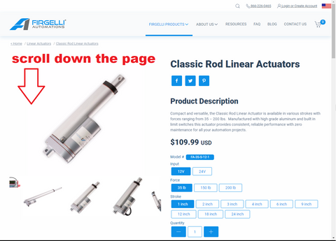
To find the maximum current rating for your actuator, navigate to the product page and locate the specifications tab. The image below shows the product page for our Classic Linear Actuator, one of our most popular models for general-purpose automation:
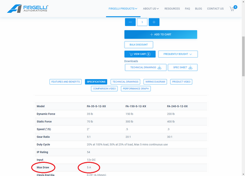
Scroll down to the specifications section, which contains the detailed electrical and mechanical parameters:

Look for the "Max Current Draw" or "Max Current Rating" value. In this example, the Classic Linear Actuator has a maximum current draw of 5 amps:
Calculating Power Requirements for Multiple Actuators
If your application uses multiple actuators powered from a single supply, you must sum the individual current requirements to determine the total current capacity needed. Use this formula:
Total Required Current = Number of Actuators × Max Current per Actuator
For example, if you're driving three Classic Linear Actuators simultaneously, each rated at 5A maximum draw, your power supply must provide at least 15 amps (3 × 5A = 15A). It's good engineering practice to add a 20-30% safety margin above the calculated requirement to account for inrush current spikes, which occur during the first moments of motor startup when the actuator overcomes static friction and accelerates the load.
For applications requiring high current capacity—such as powering four to six actuators—we recommend either the AC to DC Power Supply 12V 30A or the Water Resistant version of the same unit. Both can safely drive up to six 12V 5A linear actuators simultaneously (30A ÷ 5A = 6 actuators maximum).
For single-actuator applications or low-current micro linear actuators, a 12V battery or the 12V 5A wall adapter provides a simpler, more economical solution with direct plug-and-play connectivity.
Power Supply Options: Comprehensive Comparison
FIRGELLI Automations offers four primary categories of power supplies, each optimized for different application scenarios, installation environments, and technical requirements. Understanding the strengths and limitations of each option allows you to make an informed decision based on your specific project constraints.
12V Battery or 12V Automotive Battery
Battery power provides maximum portability and is ideal for desktop prototyping, mobile applications, or situations where AC power is unavailable. A standard 12V lead-acid, AGM, or lithium battery can power most small to medium actuators for reasonable durations depending on battery capacity (measured in amp-hours) and actuator duty cycle.
The primary advantage of battery power is flexibility—no dependence on wall outlets or power infrastructure. This makes batteries particularly suitable for vehicle installations, where the existing 12V automotive electrical system can power actuators directly. Applications like automated truck bed covers, RV slideouts, boat hatches, and mobile equipment benefit from this integration.
However, battery power has significant limitations for stationary installations. Most linear actuator applications—such as automated hatches, TV lifts, standing desks, or industrial positioning systems—remain in fixed locations where AC power is readily available. For these applications, battery power requires periodic recharging, which adds maintenance burden and introduces the risk of unexpected power depletion during operation.
Battery considerations include capacity sizing (calculating required amp-hours based on actuator current and runtime), voltage sag under load (battery voltage drops as it discharges, potentially affecting actuator performance), and temperature sensitivity (battery capacity decreases significantly in cold environments). For most stationary applications, we recommend AC-powered solutions unless portability is essential.
12V 5A AC to DC Wall Converter
The 12V 5A wall adapter represents the simplest power solution for single-actuator applications. This plug-and-play unit converts standard household AC voltage (110-120V in North America, 220-240V in most other regions with appropriate adapter) to regulated 12V DC output. The adapter connects directly to a wall outlet and provides a barrel connector or wire leads for direct actuator connection.
With a maximum output of 5 amps, this adapter is suitable for powering one standard actuator or multiple micro actuators with lower current requirements. The compact form factor and integrated design eliminate the need for separate enclosures, wire terminations, or electrical expertise—making this option ideal for hobbyists, DIY projects, and prototyping scenarios.
Limitations include the fixed 5A current ceiling and lack of environmental protection. Wall adapters should only be used in dry, indoor locations protected from moisture, dust, and mechanical damage. They are not suitable for industrial environments, outdoor installations, or applications requiring multiple high-current actuators. For projects requiring more than 5A or operating multiple actuators simultaneously, consider the 30A power supply options described below.
12V 30A AC to DC Industrial Power Supply
The 12V 30A AC to DC power supply delivers professional-grade performance for multi-actuator systems and demanding industrial applications. This open-frame switching power supply provides 360 watts of continuous power (12V × 30A = 360W), sufficient to drive up to six standard 5A actuators or three heavy-duty 10A units simultaneously.
Critical Safety Warning: This is an adjustable, open-frame power supply with exposed high-voltage terminals and internal components. It has the capability to cause serious injury or death through electrical shock. Never allow children, untrained individuals, or unauthorized personnel to access this unit. Even when disconnected from AC power, internal capacitors retain dangerous charge levels that can persist for hours. Never open the case or touch internal components. Installation must be performed by qualified personnel following all local electrical codes.
Installation and Configuration Procedure
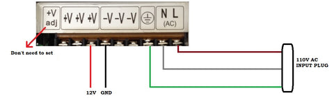
Before connecting any wiring, verify the input voltage selector switch on the side of the case. This switch must match your local AC voltage: set to 110V for North American installations or 240V for international use. Incorrect settings will damage the power supply or create fire hazards.
Input power connection requires a three-wire AC power cable with exposed conductors on one end. The screw terminals are typically labeled L (Line/Hot), N (Neutral), and ground symbol (Earth Ground). Connect the hot wire to L, neutral to N, and ground to the earth ground terminal. Use wire rated for at least 125% of the maximum current draw and appropriate for the voltage level (minimum 16 AWG recommended).
Output connections use screw terminals marked +V (positive 12V output) and -V or COM (ground/common/negative). Multiple positive and negative terminals are provided in parallel to facilitate connections to several actuators. Maintain proper polarity—reversing positive and negative connections will damage actuators. Use color-coded wire (red for positive, black for negative) to prevent connection errors.
After completing all connections, secure all wire terminations, verify no exposed conductor is accessible, and ensure the unit is mounted in a ventilated enclosure away from combustible materials. The power supply generates significant heat during operation and requires adequate airflow. Never operate the unit outside its rated specifications or exceed the 30A maximum output current.
Water Resistant 12V 30A AC to DC Power Supply
The water-resistant variant provides the same 30A output capacity as the industrial unit but features a fully sealed, IP67-rated aluminum housing that protects against moisture, dust, and environmental contaminants. This design makes it suitable for outdoor installations, humid environments, washdown areas, and marine applications where the open-frame unit would fail rapidly due to corrosion or moisture ingress.
The sealed construction provides two significant advantages: environmental protection and improved safety. The enclosed design prevents accidental contact with output terminals (though proper insulation of all connections remains critical), and the conformal coating on internal components resists humidity and temperature cycling that degrades open-frame units in harsh conditions.
Input connections consist of three pre-attached wires—ground (green/yellow), neutral (blue or white), and line/hot (brown or black)—that must be connected to an appropriate AC power source. These connections must be made inside a proper junction box or electrical enclosure, never left exposed. Cover all splices with heat shrink tubing rated for the full AC voltage plus safety margin (minimum 600V rating recommended for 120V circuits).
Output terminals provide two sets of parallel +12V and GND connections, allowing clean wire routing to multiple actuators. The screw terminals accept wire sizes from 14 to 22 AWG, though we recommend 16 or 18 AWG for most installations to minimize voltage drop over typical cable runs. When powering multiple actuators, calculate wire gauge based on total current draw and cable length to ensure voltage drop remains below 3% under full load conditions.
Step-by-Step Power Supply Selection Guide
Follow this systematic approach to identify the optimal power supply for your application:
- Verify actuator voltage rating: Confirm whether your actuator operates on 12V or 24V DC. Check the product specifications or nameplate. All FIRGELLI power supplies are 12V only.
- Determine maximum current per actuator: Locate the "Max Current Draw" specification on your actuator's product page. This is typically between 2-10 amps for standard units.
- Calculate total current requirement: Multiply the per-actuator current by the number of actuators in your system. Add 20-30% margin for safety.
- Assess installation environment: Will the power supply be located indoors in a controlled environment, or outdoors/in humid conditions? This determines whether environmental protection is necessary.
- Consider portability needs: Does your application require battery power for mobility, or can it use stationary AC power?
-
Select appropriate power supply: Use these guidelines:
- Single actuator, indoor, ≤5A: Use 12V 5A wall adapter
- Portable application or vehicle installation: Use 12V battery
- Multiple actuators (6-30A), indoor: Use 12V 30A industrial supply
- Multiple actuators (6-30A), outdoor/humid: Use water-resistant 12V 30A supply
Wire Sizing and Voltage Drop Considerations
Proper wire sizing is equally important as power supply selection. Undersized wire creates excessive voltage drop between the power supply and actuator, resulting in reduced force output, slower speeds, and potential motor overheating. As a general rule, voltage drop should not exceed 3% of the supply voltage under full load conditions, which translates to a maximum of 0.36V drop for 12V systems.
Voltage drop increases with cable length and current draw, and decreases with larger wire gauge (smaller AWG numbers indicate thicker wire). For typical installations under 10 feet with current draws under 10 amps, 16 AWG wire provides adequate performance. Longer runs or higher currents require 14 or 12 AWG wire. Use voltage drop calculators or reference tables to verify your specific installation meets the 3% guideline.
Always use stranded wire rather than solid core for actuator connections, as the flexibility prevents work hardening and wire breakage from repeated actuator movement. Use appropriate crimp connectors or soldered connections with heat shrink—never rely on twist connections or electrical tape for permanent installations. For outdoor or harsh environment installations, use marine-grade wire with tinned copper conductors and UV-resistant insulation.
Integration with Control Systems and Automation
Power supplies work in conjunction with control boxes and remote controls to provide complete actuator automation. The power supply provides the energy source, while the control system handles switching, direction reversal, and position management. For Arduino-based custom control systems, the power supply connects to motor driver circuits that switch the high-current actuator connections while the microcontroller manages logic-level control signals.
When integrating with electronic controls, maintain proper electrical isolation between control circuits and power circuits. Use optoisolators or relay modules to prevent ground loops and electrical noise from damaging sensitive control electronics. Most control boxes include this isolation internally, but custom installations require careful circuit design to ensure reliable operation and prevent EMI issues.
For feedback actuators with built-in position sensors, provide separate clean power for the feedback circuitry when possible. Although many feedback actuators can share power with the motor circuit, sensitive analog position signals can be affected by motor switching noise, potentially degrading position accuracy. Consult the actuator specifications for recommended power supply arrangements when feedback precision is critical.
Frequently Asked Questions
Can I power multiple actuators with different current ratings from one power supply?
Yes, you can power actuators with different current ratings from a single power supply, provided the total current capacity exceeds the sum of all individual maximum current draws. For example, if you have two actuators rated at 5A and one rated at 8A, you need a power supply capable of at least 18A (5A + 5A + 8A). The 30A supply would be appropriate for this application. Each actuator will only draw the current it needs—the power supply rating represents maximum available current, not the current forced through each device. Always size the power supply for the sum of maximum possible draws to prevent overload conditions.
Why does my power supply make a humming or buzzing sound during operation?
A slight humming sound from switching power supplies is normal and results from the high-frequency switching of internal transistors and transformer laminations vibrating at the switching frequency (typically 50-100 kHz). However, loud buzzing, especially under load, may indicate insufficient power supply capacity for your application—the unit is operating at or near its maximum rating and may be entering current-limiting protection mode. If buzzing is excessive, verify your total current draw doesn't exceed the supply rating, check for short circuits or damaged actuators drawing excessive current, and ensure the power supply has adequate ventilation to prevent thermal derating of output capacity.
Can I use solar panels to power linear actuators?
Solar power is feasible for linear actuator applications but requires proper system design including solar panels, charge controller, and battery storage. Solar panels produce variable voltage and current depending on sunlight intensity, making direct connection unsuitable for actuators requiring stable 12V supply. A typical off-grid solar setup would use panels rated for 20-30% above your power requirements to charge a 12V deep-cycle battery bank through a solar charge controller. The actuators then operate from the battery, which provides stable voltage and can supply high surge currents during actuator startup. Size your battery capacity based on the total energy consumption per day and number of days of autonomy desired without sunlight.
What happens if I use too-small wire gauge and experience voltage drop?
Excessive voltage drop reduces the effective voltage reaching the actuator, which directly impacts performance. Actuator force output is proportional to voltage—reducing voltage by 20% typically reduces available force by approximately 40% due to the squared relationship between voltage and power. Speed also decreases with reduced voltage. In severe cases, voltage drop under load may be sufficient to prevent the actuator from moving at all, or cause it to stall partway through its stroke when current demand peaks. Additionally, the resistance causing voltage drop converts electrical energy to heat in the wire, potentially creating fire hazards in extreme cases. Always use appropriately sized wire for your current draw and cable length, following the 3% voltage drop guideline.
Do switching power supplies create electrical noise that affects other electronics?
Switching power supplies can generate electrical noise in the form of conducted EMI on power lines and radiated EMI from the supply itself and connected wiring. Quality power supplies include input and output filtering to minimize this noise, but some applications with sensitive electronics may require additional measures. Use shielded cable for actuator connections when installing near audio/video equipment, use twisted pair wiring to cancel magnetic field emissions, and consider adding ferrite cores on power cables near noise-sensitive equipment. For critical applications, an isolation transformer or filtered power distribution unit between the power supply and sensitive equipment provides additional protection. Most consumer electronics and control systems are sufficiently immune to power supply noise that these measures are unnecessary, but laboratory instruments, audio equipment, and medical devices may require extra attention.
What additional considerations apply for outdoor power supply installations?
Outdoor installations require the water-resistant power supply variant at minimum, but complete weatherproofing demands attention to all system components. All AC and DC electrical connections must be housed in NEMA-rated enclosures appropriate for your environment (NEMA 3R minimum for rain protection, NEMA 4X for washdown or coastal environments). Use conduit or UV-resistant cable for all outdoor wiring runs, and seal all conduit entry points with appropriate fittings. Apply dielectric grease to all connectors to prevent corrosion. Ensure the enclosure containing the power supply has adequate ventilation to prevent heat buildup while maintaining water resistance—typically achieved with breathable vent plugs that allow air exchange while blocking liquid water. Consider temperature extremes: power supplies derate at high temperatures and may fail to start in extreme cold. Install in shaded locations when possible and verify the power supply's operating temperature range covers your climate conditions.


