Precision analog circuits hit a hard limit — not from bad components or poor layout, but from the random thermal motion of electrons inside every resistor. That limit is Johnson-Nyquist noise, and ignoring it will break any low-noise design. Use this Resistor Noise Interactive Calculator to calculate thermal noise spectral density, total integrated noise voltage, SNR, and equivalent noise temperature using resistance, temperature, and bandwidth inputs. It matters in precision instrumentation, low-noise amplifier front-ends, sensor interface circuits, and any measurement system where the noise floor determines what you can resolve. This page covers the governing equations, a worked thermocouple example, practical design rules, and a full FAQ.
What is resistor thermal noise?
Resistor thermal noise — also called Johnson-Nyquist noise — is a small random voltage generated by every resistor just from heat. The hotter the resistor and the wider the frequency range you measure, the more noise you get. It sets the absolute minimum noise floor for any circuit using that resistor.
Simple Explanation
Think of electrons inside a resistor as constantly jostling around like molecules in warm water — they never sit still. All that random movement creates tiny random voltage spikes across the resistor terminals, even when no current is flowing. The bigger the resistor and the warmer it is, the more jostling, and the louder those random spikes get.
📐 Browse all 1000+ Interactive Calculators
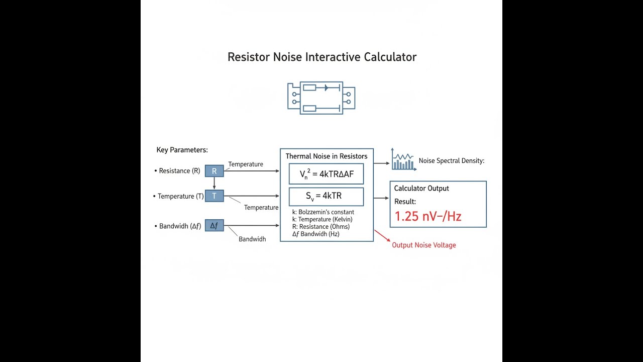
Noise Voltage Diagram

How to Use This Calculator
- Select your calculation mode from the dropdown — choose from total noise voltage, spectral density, bandwidth, maximum resistance, SNR, or equivalent noise temperature.
- Enter the relevant inputs for your chosen mode: resistance (Ω), temperature (K), bandwidth (Hz), signal voltage, or measured noise density as applicable.
- Use the Try Example button to pre-fill realistic values if you want a starting point.
- Click Calculate to see your result.
Interactive Resistor Noise Calculator
Resistor Noise Interactive Visualizer
Watch how resistance, temperature, and bandwidth affect thermal noise generation in real-time. Adjust parameters to see Johnson-Nyquist noise calculations with visual feedback on noise magnitude and frequency distribution.
SPECTRAL DENSITY
12.87 nV/√Hz
TOTAL NOISE
0.41 µV
PEAK-TO-PEAK
2.45 µV
FIRGELLI Automations — Interactive Engineering Calculators
Governing Equations
Simple Example
A 10 kΩ resistor at room temperature (298 K) with a 1 kHz bandwidth:
- Noise spectral density: √(4 × 1.381×10⁻²³ × 298 × 10000) = 12.87 nV/√Hz
- Total integrated noise: 12.87 nV/√Hz × √1000 = 0.407 µVRMS
- Peak-to-peak noise (6σ): 0.407 × 2√2 = 1.15 µVPP
Thermal Noise Spectral Density
Use the formula below to calculate thermal noise spectral density.
en = √(4kBTR)
Where:
- en = Noise voltage spectral density (V/√Hz)
- kB = Boltzmann constant = 1.380649 × 10⁻²³ J/K
- T = Absolute temperature (K)
- R = Resistance (Ω)
Total Integrated Noise Voltage
Use the formula below to calculate total integrated noise voltage.
vn,RMS = en √Δf = √(4kBTRΔf)
Where:
- vn,RMS = Total RMS noise voltage (VRMS)
- Δf = Noise bandwidth (Hz)
Signal-to-Noise Ratio
Use the formula below to calculate signal-to-noise ratio.
SNRdB = 20 log10(Vsignal / vn,RMS)
Where:
- SNRdB = Signal-to-noise ratio (decibels)
- Vsignal = RMS signal voltage (VRMS)
- vn,RMS = RMS noise voltage (VRMS)
Equivalent Noise Temperature
Use the formula below to calculate equivalent noise temperature.
Teq = en2 / (4kBR)
Where:
- Teq = Equivalent noise temperature (K)
- en = Measured noise spectral density (V/√Hz)
Theory & Practical Applications
Resistor noise represents the fundamental quantum-thermodynamic limit on measurement resolution in electronic systems. Unlike other noise sources that can be mitigated through careful design or component selection, thermal noise—also called Johnson-Nyquist noise—is an intrinsic property of any dissipative electrical element at non-zero temperature. Understanding this noise mechanism and its calculation is essential for precision instrumentation, low-noise amplifier design, sensor interfaces, and any application where the noise floor determines system performance.
Physical Origin of Thermal Noise
Thermal noise originates from the random thermal motion of charge carriers within a conductor. At any temperature above absolute zero, electrons possess kinetic energy proportional to kBT and undergo continuous random collisions with the crystal lattice. These collisions produce fluctuating voltages across the conductor terminals even in the absence of applied current. The voltage fluctuations are Gaussian-distributed with zero mean and exhibit a flat power spectral density up to frequencies approaching 1 THz at room temperature, where quantum effects begin to dominate. This white noise characteristic means that each Hz of bandwidth contributes equally to the total integrated noise power.
The factor of 4 in the thermal noise equation arises from the two-sided power spectral density representation and the contribution of both real and imaginary components of impedance fluctuations. The square root relationship between noise voltage and resistance has critical design implications: doubling the resistance increases noise voltage by only √2 (approximately 1.41×), not 2×. This sublinear scaling explains why high-impedance circuits are not always proportionally noisier than low-impedance equivalents when considering current noise contributions.
Bandwidth Dependence and Integration
The total noise voltage depends on the square root of bandwidth because noise power adds incoherently across frequency. When integrating noise spectral density over bandwidth Δf, the relationship vn = en√Δf assumes a brick-wall filter response with sharp cutoffs at f1 and f2, where Δf = f2 - f1. Real filters exhibit gradual roll-off, requiring noise bandwidth correction factors. For a single-pole RC filter with 3-dB corner frequency fc, the equivalent noise bandwidth is πfc/2, approximately 1.57× the 3-dB bandwidth. Second-order Butterworth filters have noise bandwidth factors near 1.11× the 3-dB bandwidth. Failing to account for these factors can introduce 20-30% error in noise predictions for precision circuits.
One critical but often overlooked aspect: noise bandwidth must account for the entire signal chain, not just the intentional filtering. Parasitic capacitances, PCB trace inductance, and amplifier input capacitance all contribute to bandwidth limitation and thus affect integrated noise. A 10 kΩ source resistance with 15 pF of total input capacitance creates a corner frequency near 1.06 MHz, establishing an effective noise bandwidth that may dominate over any subsequent intentional filtering. This is why ultra-low-noise designs minimize input capacitance through careful layout and guard ring implementation.
Temperature Effects and Thermal Management
The linear dependence of noise on √T suggests that cooling resistive elements reduces thermal noise proportionally. Lowering temperature from 300 K to 77 K (liquid nitrogen) reduces noise voltage by √(77/300) ≈ 0.507, or approximately -5.9 dB. Cryogenic systems operating at 4.2 K (liquid helium) achieve another factor of 4.3 reduction. However, these gains must be weighed against system complexity, power dissipation constraints in cryogenic environments, and the emergence of other noise mechanisms that may dominate at low temperatures. Shot noise, for instance, becomes increasingly significant relative to thermal noise as temperature decreases, particularly in high-gain photodetector applications.
Resistor self-heating presents a subtle challenge in noise-critical applications. The effective noise temperature of a resistor carrying current exceeds ambient temperature by ΔT = Pdissipated / (θJA × Asurface), where θJA is the thermal resistance. A 10 kΩ resistor dissipating 1 mW in a small 0603 package may exhibit junction temperatures 20-30°C above ambient, increasing noise by approximately 5%. Precision circuits use larger resistor packages, lower dissipation levels, or thermal coupling to heat sinks to maintain lower effective noise temperatures.
Worked Engineering Example: Precision Thermocouple Interface
A precision data acquisition system interfaces with a Type K thermocouple (41 µV/°C Seebeck coefficient) for temperature measurement in a laboratory environment. The system requires 0.01°C resolution over a 0-1000°C range with a measurement bandwidth of 2 Hz for adequate response time while rejecting high-frequency interference. The thermocouple presents approximately 20 Ω source impedance. The design must determine whether resistor thermal noise limits achievable resolution.
Given Parameters:
- Thermocouple Seebeck coefficient: S = 41 µV/°C
- Source resistance: Rsource = 20 Ω
- Ambient temperature: T = 298.15 K (25°C)
- Measurement bandwidth: Δf = 2 Hz
- Target resolution: 0.01°C
- Amplifier input resistance: Ramp = 10 MΩ (negligible loading)
Step 1: Calculate Required Voltage Resolution
To resolve 0.01°C temperature change:
Vresolution = S × ΔT = 41 µV/°C × 0.01°C = 0.41 µV
Step 2: Calculate Thermocouple Thermal Noise
Noise spectral density of 20 Ω source:
en = √(4 × 1.380649×10-23 × 298.15 × 20)
en = √(3.290×10⁻¹⁹) = 1.814×10⁻⁹ V/√Hz = 1.814 nV/√Hz
Integrated noise over 2 Hz bandwidth:
vn,source = 1.814×10⁻⁹ × √2 = 2.565×10⁻⁹ V = 2.565 nVRMS
Step 3: Equivalent Temperature Noise
Convert noise voltage to equivalent temperature uncertainty:
ΔTnoise = vn,source / S = 2.565×10⁻⁹ V / (41×10-6 V/°C)
ΔTnoise = 6.26×10⁻⁵ °C = 0.0000626°C
Step 4: System Noise Budget Analysis
The thermal noise contribution (62.6 µK) is 160 times smaller than the target resolution (0.01°C = 10 mK). To achieve the target resolution, the total system noise budget must account for amplifier voltage noise, current noise interacting with source impedance, 1/f noise, quantization noise from the ADC, and interference pickup. Assuming a typical instrumentation amplifier with 5 nV/√Hz voltage noise and 100 fA/√Hz current noise:
Amplifier voltage noise contribution:
vn,amp = 5×10⁻⁹ × √2 = 7.07 nVRMS
Amplifier current noise contribution (interacting with 20 Ω):
vn,current = (100×10-15) × 20 × √2 = 2.83×10⁻¹² V (negligible)
Total uncorrelated noise (RSS combination):
vn,total = √(vn,source2 + vn,amp2)
vn,total = √((2.565×10⁻⁹)2 + (7.07×10⁻⁹)2) = 7.52 nVRMS
Equivalent temperature noise floor:
ΔTtotal = 7.52×10⁻⁹ / (41×10-6) = 0.000183°C = 0.183 mK
Step 5: SNR and Effective Bits
For a 1000°C full-scale range (41 mV signal):
SNRdB = 20 log10(0.041 / 7.52×10⁻⁹) = 134.7 dB
Effective number of bits (ENOB):
ENOB = (134.7 - 1.76) / 6.02 ≈ 22.1 bits
Conclusion: The thermocouple thermal noise contributes only 34% of the total noise budget, with the instrumentation amplifier dominating. A 24-bit ADC would theoretically provide 145 dB dynamic range (sufficient for this application), but achieving the full 0.01°C resolution requires addressing amplifier noise, thermal EMF offsets at connections, common-mode interference rejection, and 1/f noise below 2 Hz. The low source impedance of the thermocouple is advantageous—higher impedance sensors would require even more careful noise analysis and potentially active buffering at the sensor itself.
Practical Design Considerations
In precision analog circuits, resistor selection involves trade-offs between noise, voltage coefficient, temperature coefficient, and cost. Metal film resistors exhibit lower 1/f noise than carbon composition types but still generate significant excess noise at low frequencies. For the lowest noise applications below 100 Hz, wirewound or thin-film resistors provide superior performance but at higher cost and with parasitic inductance that complicates high-frequency designs. The noise contribution of a 10 kΩ thin-film resistor at room temperature is approximately 12.8 nV/√Hz—this sets the absolute minimum noise floor for any circuit using this resistance value.
Parallel resistor combinations reduce thermal noise because parallel resistances add reciprocally while noise powers add directly. Two 20 kΩ resistors in parallel present 10 kΩ resistance but with noise spectral density equal to a single 10 kΩ resistor, not two 20 kΩ resistors. This is sometimes exploited in ultra-low-noise designs where physical constraints prevent using lower-valued single resistors. However, the technique increases component count, board area, and 1/f noise contributions due to manufacturing variations between parallel elements.
For more precision electronics calculators, visit the FIRGELLI Engineering Calculator Hub.
Frequently Asked Questions
Free Engineering Calculators
Explore our complete library of free engineering and physics calculators.
Browse All Calculators →🔗 Explore More Free Engineering Calculators
- I2C/SPI Bus Speed & Pull-up Resistor Sizing
- Capacitor Charge Discharge Calculator — RC Circuit
- Wheatstone Bridge Calculator
- RLC Circuit Calculator — Resonance Impedance
- Free Space Path Loss Calculator
- Capacitors In Series Calculator
- Spherical Capacitor Calculator
- Power Factor Calculator and Correction
- Voltage Divider & ADC Resolution Calculator
- Voltage Divider Calculator
About the Author
Robbie Dickson — Chief Engineer & Founder, FIRGELLI Automations
Robbie Dickson brings over two decades of engineering expertise to FIRGELLI Automations. With a distinguished career at Rolls-Royce, BMW, and Ford, he has deep expertise in mechanical systems, actuator technology, and precision engineering.
Need to implement these calculations?
Explore the precision-engineered motion control solutions used by top engineers.


