If you’re building high-frequency circuits or working on power electronics, ignoring skin effect just isn’t an option. At those frequencies, it usually dominates losses and determines your wire or trace size. This Skin Depth Interactive Calculator gives you a practical way to get skin depth, AC resistance ratio, and how much of your conductor cross-section is really doing anything for you. Enter frequency, conductivity, relative permeability, and wire radius—see useful answers and spot design bottlenecks before hardware hits your bench. These numbers affect everything from RF shielding to GHz PCB traces and the windings in ferrite transformers. You’ll also find fundamental equations, worked-through inductor design, straightforward theory, and answers to real engineering questions further down the page.
What is skin depth?
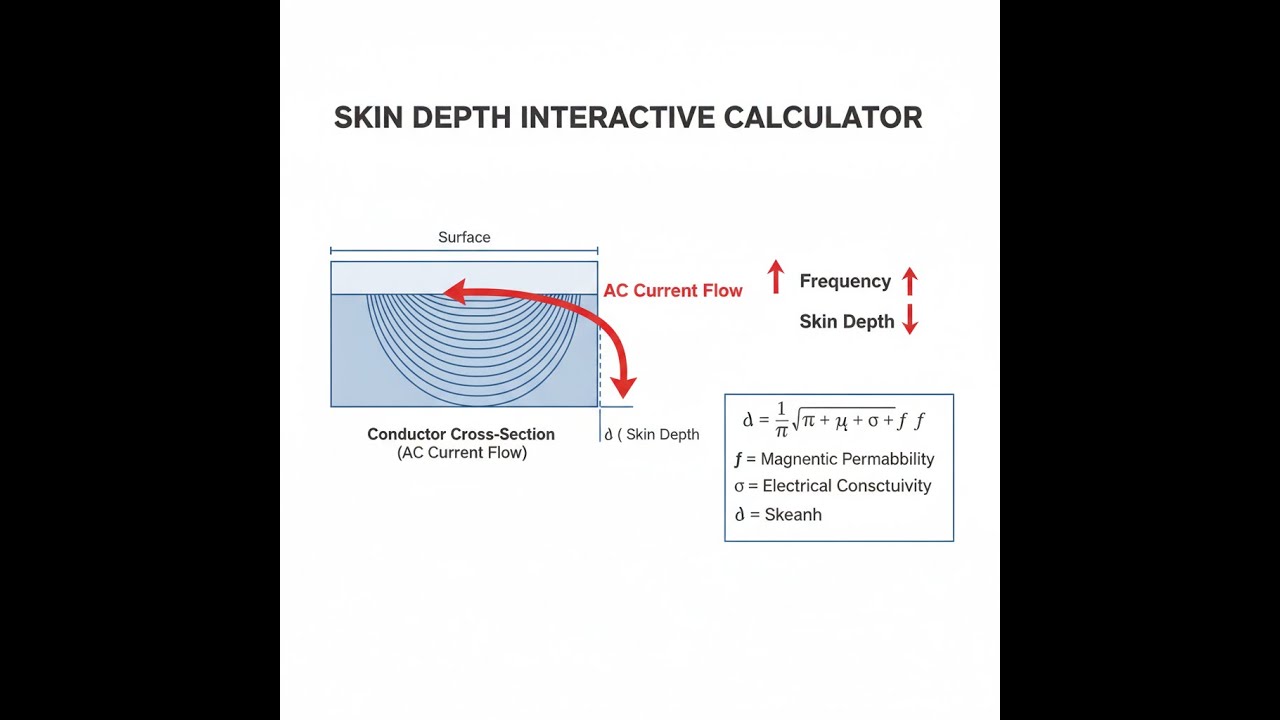
Skin depth is the distance under a conductor’s surface where the AC current density drops to about 37% of the value at the surface. Higher frequency means a shallower current—so AC current “hugs” the outer layer of your wire or trace more and more as frequency goes up.
Simple Explanation
Imagine a copper wire carrying AC like a pipe with water flowing only around the inside edge—hardly any in the center. At low frequencies, all of the wire’s cross-section carries current. At high frequencies, almost all of it travels near the surface. That’s why at RF, thick solid wires don’t help—they act like much thinner wires for AC. Litz wire (a bundle of thin, insulated strands) spreads current out and is a common fix for this problem.
📐 Browse all 1000+ Interactive Calculators
Skin Depth Visualization

Skin Depth Calculator
How to Use This Calculator
This calculator is intended for education, concept evaluation, and preliminary design. Results are based on the equations and assumptions described on this page, but cannot account for every real-world load case, tolerance, material property, environmental condition, installation detail, safety factor, code, or regulatory requirement. Verify all inputs, assumptions, units, and results independently before selecting components or using the result in a real application. Safety-critical, structural, medical, lifting, transportation, or regulated applications must be reviewed by a qualified engineer.
Questions about this calculator or found an error? Message our engineering team.
- Pick the calculation mode: skin depth, frequency, conductivity, permeability, AC resistance ratio, or effective conducting area.
- Enter the right conductivity (S/m) and relative permeability for your material. Take a look at the reference values for a quick start if you’re working with copper or aluminum.
- Fill in frequency (Hz) and, if needed, wire radius (m) for your setup.
- Click Calculate and get the answer.
Skin Depth Interactive Visualizer
You’ll see in real time how AC current density gets squeezed toward the surface as you dial up the frequency, increase permeability, or use a more resistive material. Move the sliders and spot how skin depth, resistance ratio, and real conducting area shift—the effect is immediate and gives you an engineering feel for what’s really happening inside your wire.
SKIN DEPTH
65.4 μm
AC/DC RATIO
7.65×
EFF. AREA
13.1%
FIRGELLI Automations — Interactive Engineering Calculators
Fundamental Equations
The formula below gives you skin depth based on frequency, conductivity, and permeability—about as direct as you’ll get in real-world design work.
Skin Depth (Classical Formula)
δ = √(2 / (ω μ σ)) = √(1 / (π f μ σ))
Where:
- δ = skin depth (m) — depth at which current density falls to 1/e of surface value
- ω = angular frequency = 2πf (rad/s)
- f = frequency (Hz)
- μ = absolute permeability = μrμ0 (H/m)
- μr = relative permeability (dimensionless, ~1 for non-magnetic materials)
- μ0 = permeability of free space = 4π × 10-7 H/m
- σ = electrical conductivity (S/m or Ω-1m-1)
Current Density Decay
J(x) = J0 e-x/δ
Where:
- J(x) = current density at depth x (A/m²)
- J0 = surface current density (A/m²)
- x = depth from surface (m)
- e = Euler's number ≈ 2.71828
Note: At x = δ, current density drops to ~37%; at x = 3δ, only ~5% remains; at x = 5δ, less than 1%.
AC Resistance Ratio (Cylindrical Conductor)
RAC / RDC ≈ (r / 2δ) for r >> δ
Where:
- RAC = AC resistance at frequency f (Ω)
- RDC = DC resistance (Ω)
- r = conductor radius (m)
Approximation valid when wire radius greatly exceeds skin depth. For precise calculations, use Bessel function solutions.
Surface Impedance
Zs = (1 + j) / (σ δ) = √(j ω μ / σ)
Where:
- Zs = surface impedance (Ω)
- j = imaginary unit (√-1)
- Real and imaginary parts equal: Rs = Xs = 1/(σδ)
Simple Example
Copper wire at 1 MHz. σ = 5.96 × 10⁷ S/m, μr = 1, f = 1,000,000 Hz.
δ = √(1 / (π × 1×10⁶ × 1.257×10⁻⁶ × 5.96×10⁷)) = √(1 / 2.355×10⁸) ≈ 65 μm (0.065 mm).
A 1 mm diameter copper wire at 1 MHz has r/δ ≈ 7.7 — strong skin effect. AC resistance is roughly 3.8× its DC value.
Theory & Practical Applications
Physical Mechanism of the Skin Effect
Skin effect starts because AC current generates a changing magnetic field inside your conductor. That field creates eddy currents—essentially little loops of current—inside the metal. Those eddy currents work against the main current in the center and build it up more near the surface. The result: current density falls off exponentially with depth, right from Maxwell’s equations. The skin depth δ shows how deep that current gets before it’s almost gone. At 3 to 5 times δ, there isn’t enough left to matter.
Current only having a thin cross-section to flow through means effective resistance goes up for AC. So all your I²R losses go up unless you redesign the conductor for shorter, thinner current paths—either more surface area or by switching to litz wire, tubing, or flat conductors.
Material Dependencies and Non-Obvious Behavior
The basic formula for skin depth says it’s a function of frequency, permeability, and conductivity. But copper’s conductivity, for example, is only its “book” value at 20°C. If your bus bar runs hot, factor in the conductivity drop—about 0.4% per °C above 20°C. A copper bar at 70°C has 20% higher resistance than you’d expect using a textbook value. This shrinks skin depth and further raises AC resistance when things run hot. For high-current builds, don’t overlook this or you’ll under-design.
Magnetic materials like transformer core steels behave even less predictably. Their permeability drops way off at higher frequencies. At a few Hertz, steel might have μr = 4000; at 10 kHz, it’s often much lower. Don’t try to use low-frequency values in a kilohertz design—always reference the right frequency response chart or use measured data when designing with ferromagnetic parts above a few hundred Hertz. Otherwise, calculations will not match reality.
High-Frequency Circuit Design Implications
At RF, skin effect is usually your main conductor loss. Above a few hundred MHz, skin depth in copper drops below the typical surface roughness of PCB copper. That means the “bumpy” surface matters—a rougher PCB trace makes current take a longer path, raising AC resistance well above what smooth-copper calculations would say. If you’re designing for 5G, radar, or other microwave work, using low-roughness copper can cut your real AC losses in half—or more.
For coax cable at those frequencies, current only flows in the thinnest outer layer on the center conductor. There’s no point in solid cable beyond a few skin depths thick—hollow tubing works just as well for RF and saves weight and copper. But don’t skimp on the tube wall thickness too much: let current decay to near zero to keep shielding and performance as calculated. Practical limit: at least 3-5 skin depths wall for good containment.
Power System and Motor Design Applications
At mains frequencies (50/60 Hz), copper’s skin depth is about 9 mm, so most wires don’t see much skin effect. But things change quickly once harmonics or fast transients appear. For example, variable frequency drives (VFDs) inject strong harmonics, and at the 11th harmonic of 60 Hz (660 Hz), skin depth is just 3 mm or so. Resistance for these harmonics is much higher, causing windings to heat up faster than you’d expect from DC values alone. Using multi-strand or smaller-diameter wires in large motor windings helps keep losses down in these conditions.
Busbars for substations and industrial power must be sized for transient skin effect too, not just for 50/60 Hz currents. Faults can create currents full of high-frequency content, which will have less penetration—so resistance (and therefore heating and voltage drop) during a fault is much higher than in continuous-duty calculations. A good approach is to assume 50–100% higher AC resistance in busbars for these brief but critical cases.
Shielding Effectiveness and EMC Design
Skin effect is what lets a metal box attenuate stray fields. But to actually get decent shielding, your metal needs to be a few skin depths thick at the frequency you want to block. For example, at 100 kHz, aluminum skin depth is about 260 μm, so normal sheet metal thickness is fine. But up at 1 MHz, thin foil starts to let some energy through. You need thicker aluminum or higher conductivity surfaces (like copper or silver plate) if you want really high shielding in tough EMC problems. There’s a logarithmic relationship—each skin depth adds about 17 dB attenuation—so getting “perfect” shielding by just making the wall thicker gets expensive fast.
Litz Wire and Proximity Effect Mitigation
Litz wire splits a conductor into many insulated strands, ideally each just below twice the skin depth. Current divides pretty evenly among all the strands, so AC resistance stays low. But proximity effect (currents induced in nearby conductors or windings) can still make losses spike, even for litz wire, if winding geometry gets too tight. As strands or wires get packed closer, unwanted coupling grows as the square of their diameter to spacing ratio. For practical purposes, choose a strand size close to 2× the skin depth for the frequency in question. Going finer than that makes construction harder without much gain; going coarser costs you in AC losses. If you design custom windings, finding the right balance often means doing a few prototypes.
Worked Example: High-Frequency Inductor Design
Say you need a 10 μH air-core inductor for 500 kHz, carrying 5 A RMS, DC resistance less than 50 mΩ, and AC losses as low as possible. Here’s how the numbers play out:
Step 1: Calculate skin depth in copper at 500 kHz
f = 500 kHz, σ = 5.96 × 10⁷ S/m, μr = 1
μ = 1.257 × 10⁻⁶ H/m
δ = √(2/(2π × 5×10⁵ × 1.257×10⁻⁶ × 5.96×10⁷)) = √(2/(1.870×10⁹)) = √(1.070×10⁻⁹) = 32.7 μm
Step 2: Find max wire diameter for low skin effect
Solid wire diameter should ideally be no greater than 4 skin depths, so about 130 μm. That’s AWG 38—DC resistance will now be huge for the length needed.
Step 3: Wire gauge needed for DC resistance
Assuming you need 3 m of wire: to keep under 50 mΩ DC, area needs to be 1.008 mm², which is about AWG 17 (1.13 mm diameter).
Step 4: AC resistance for that wire
AWG 17: radius = 0.575 mm, r/δ = 575/32.7 = 17.6, so RAC/RDC ≈ 8.8. That’s over 400 mΩ AC—completely impractical.
Step 5: Specify litz construction
Use strands at about 2δ ≈ 65 μm diameter (AWG 42). For 1 mm² total area, you’ll need about 315 of these strands, so a 315/42 litz construction is about right.
Step 6: AC resistance for litz
Each strand runs close to its DC resistance. Factor in a bit of extra loss for imperfections, but typically only about 10% higher than the DC value. Power loss at 5 A is then about 1.4 W, which is manageable. With solid wire, you’d be at 11 W—likely a thermal failure in a compact winding.
Conclusion: This is why pretty much every high-frequency power inductor uses litz, not solid wire, above a few hundred kHz.
Edge Cases and Common Design Errors
One easy mistake: designing everything to DC resistance and never checking AC resistance. You do this, and your prototype transformer or inductor will often overheat badly at high frequencies. Temperature rise then makes conductivity even worse, and things can spiral until something fails.
Another common error in PCB design: expecting thicker copper foil to lower trace resistance at higher frequencies. Skin effect puts most of your current in the top 50–70 μm (at MHz), so adding copper thickness below that just adds thermal mass—not lower resistance where it counts. For RF traces, make them wider rather than thicker as frequency rises.
Frequently Asked Questions
Free Engineering Calculators
Explore our complete library of free engineering and physics calculators.
Browse All Calculators →🔗 Explore More Free Engineering Calculators
- RLC Circuit Calculator — Resonance Impedance
- Low-Pass RC Filter Calculator — Cutoff Frequency
- Resistor Color Code Calculator
- Capacitor Charge Discharge Calculator — RC Circuit
- Capacitors In Series Calculator
- Bridge Rectifier Calculator
- Inductor Energy Calculator
- Power Factor Calculator and Correction
- Voltage Divider Calculator
- Transformer Turns Ratio Calculator
About the Author
Robbie Dickson — Chief Engineer & Founder, FIRGELLI Automations
Robbie Dickson brings over two decades of engineering expertise to FIRGELLI Automations. With a distinguished career at Rolls-Royce, BMW, and Ford, he has deep expertise in mechanical systems, actuator technology, and precision engineering.
Video Walkthrough - How to Use This Calculator
Need to implement these calculations?
Explore the precision-engineered motion control solutions used by top engineers.


