Sizing a spherical capacitor means balancing 3 competing variables — inner radius, outer radius, and dielectric material — against voltage limits and energy storage requirements. Use this Spherical Capacitor Calculator to calculate capacitance, stored energy, electric field strength, and critical dimensions using inner radius (r₁), outer radius (r₂), and relative permittivity (εᵣ). It matters in high-voltage equipment design, electrostatic shielding, and Van de Graaff generator engineering, where field concentration at the inner conductor surface drives every key decision. This page covers the governing formula, a worked design example, field distribution theory, and a full FAQ.
What is a spherical capacitor?
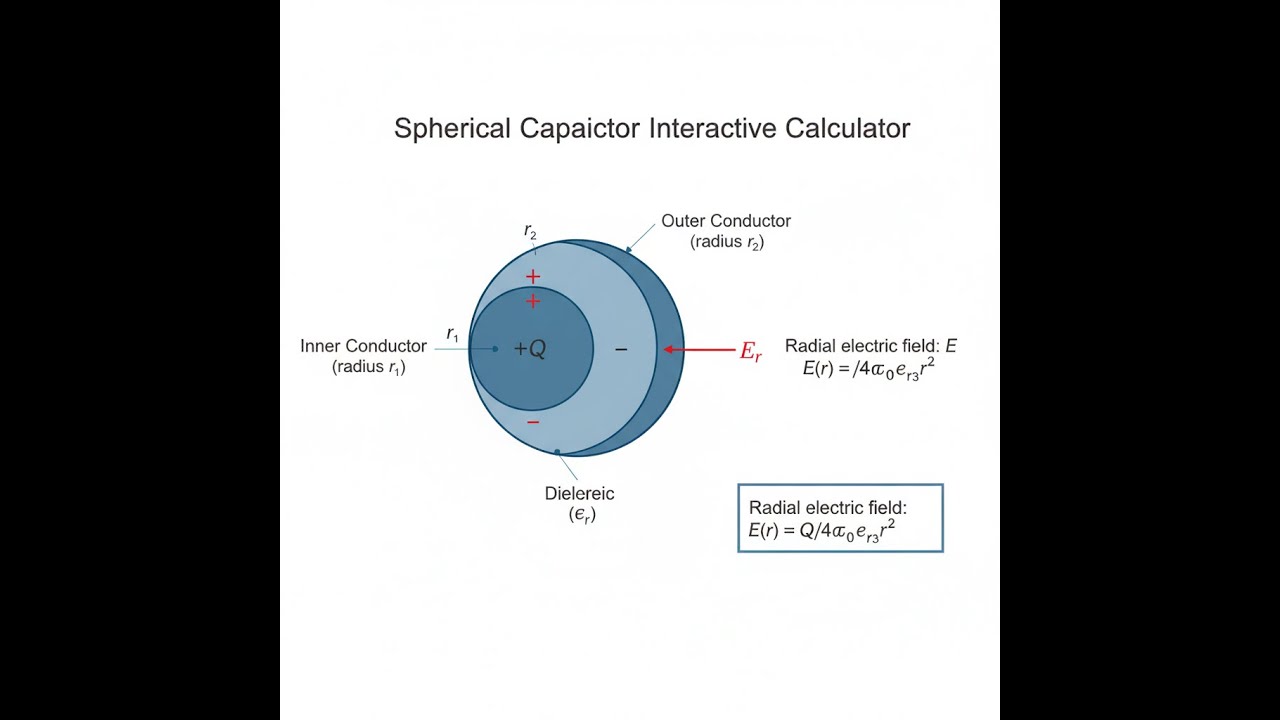
A spherical capacitor is two concentric conducting spheres — one inside the other — separated by a dielectric material. Applying voltage between them stores electrical energy in the gap, with capacitance determined by the sphere radii and the dielectric between them.
Simple Explanation
Think of it like a ball inside a hollow shell — both made of metal, with an insulating material filling the space between them. The inner ball holds charge, the outer shell contains the electric field, and the gap between them determines how much energy the system can store. The smaller the gap relative to the sphere size, the more capacitance you get — just like squeezing more onto a smaller shelf.
📐 Browse all 1000+ Interactive Calculators
Spherical Capacitor Diagram

How to Use This Calculator
- Select your calculation mode from the dropdown — choose what you want to solve for (capacitance, outer radius, inner radius, stored energy, electric field, or voltage).
- Enter the known values for your system: inner radius (r₁) and/or outer radius (r₂) in meters, and relative permittivity (εᵣ) of your dielectric material.
- If your selected mode requires it, enter voltage (V), charge (Q), capacitance (C), or evaluation radius (r) in the fields that appear.
- Click Calculate to see your result.
Interactive Calculator
Spherical Capacitor Interactive Visualizer
Watch how electric field concentration peaks at the inner sphere surface as you adjust the radius ratio and dielectric properties. See instantly how field strength decreases with 1/r² distribution while capacitance depends on the critical gap spacing between conductors.
CAPACITANCE
24.3 pF
STORED ENERGY
48.6 nJ
MAX E-FIELD
1.25 MV/m
RADIUS RATIO
3.00
FIRGELLI Automations — Interactive Engineering Calculators
Governing Equations
Use the formula below to calculate spherical capacitor properties.
Capacitance:
C = 4πε₀εᵣr₁r₂ / (r₂ − r₁)
Electric Field (at radius r):
E(r) = Q / (4πε₀εᵣr²)
Voltage:
V = Q(r₂ − r₁) / (4πε₀εᵣr₁r₂)
Stored Energy:
U = ½CV²
Variable Definitions:
- C = Capacitance (farads, F)
- r₁ = Inner conductor radius (meters, m)
- r₂ = Outer conductor radius (meters, m)
- ε₀ = Vacuum permittivity = 8.854 × 10⁻¹² F/m
- εᵣ = Relative permittivity of dielectric (dimensionless)
- Q = Charge on inner conductor (coulombs, C)
- V = Potential difference (volts, V)
- E(r) = Electric field magnitude at radius r (V/m)
- U = Stored electrostatic energy (joules, J)
Simple Example
Inner radius r₁ = 0.05 m, outer radius r₂ = 0.10 m, air dielectric (εᵣ = 1):
- Capacitance: C = 4π × 8.854×10⁻¹² × 1 × 0.05 × 0.10 / (0.10 − 0.05) ≈ 11.1 pF
- At 1000 V: stored energy U = ½ × 11.1×10⁻¹² × 1000² ≈ 5.55 × 10⁻⁶ J
- Inner surface field: E(r₁) = Q / (4πε₀r₁²) — highest field point in the system
Theory & Practical Applications
Fundamental Physics of Spherical Capacitors
The spherical capacitor represents one of the few electrostatic configurations amenable to exact analytical solution through Gauss's law. Unlike parallel-plate capacitors where field uniformity simplifies analysis, the spherical geometry introduces a 1/r² radial field dependence that creates extreme field concentration at the inner conductor surface. This fundamental characteristic makes spherical capacitors simultaneously valuable for high-voltage isolation and problematic for dielectric breakdown considerations. The capacitance formula C = 4πε₀εᵣr₁r₂/(r₂ − r₁) reveals a critical non-intuitive behavior: capacitance increases with both radii, but the rate of increase diminishes as the gap (r₂ − r₁) widens, eventually approaching the limiting case of an isolated sphere where C → 4πε₀εᵣr₁ as r₂ → ∞.
The electric field distribution E(r) = Q/(4πε₀εᵣr²) exhibits maximum intensity at the inner conductor surface (r = r₁), where field strength can exceed the average field by factors of 2-10 depending on the radius ratio. This concentration effect drives the design constraint that spherical capacitors must be engineered with inner conductor radii large enough to prevent corona discharge or dielectric breakdown at the inner surface, even when the average field strength appears safe. For air-dielectric systems operating at atmospheric pressure, the breakdown threshold of approximately 3 × 10⁶ V/m at the inner surface typically limits practical voltage operation, while high-permittivity solid dielectrics like ceramic (εᵣ = 10-100) enable higher energy densities at the cost of reduced breakdown strength compared to vacuum or sulfur hexafluoride gas.
Energy Storage and Field Energy Density
The stored electrostatic energy U = ½CV² manifests physically as field energy distributed throughout the dielectric volume, with energy density u(r) = ½ε₀εᵣE² varying as 1/r⁴. This fourth-power radial dependence means that despite the infinite theoretical volume available, approximately 90% of stored energy resides within the first two gap widths from the inner conductor. For precision energy storage applications, this concentration demands careful thermal management at the inner conductor where both field energy density and ohmic heating from leakage currents peak simultaneously. In Van de Graaff generators operating at megavolt potentials, the spherical terminal capacitance to ground (approximated as r₁ = 0.5-1.0 m, r₂ → ∞) typically stores 50-200 joules at full charge — enough energy to deliver a noticeable but sub-lethal shock, illustrating why such systems require grounding sticks before maintenance.
Industrial Applications Across Scales
Spherical capacitors find application wherever three-dimensional field control or omnidirectional shielding is required. In high-voltage testing laboratories, calibrated spherical reference capacitors with precisely machined brass shells (r₁ = 50.00 mm, r₂ = 100.00 mm, tolerance ±0.01 mm) serve as traceable capacitance standards because their geometry eliminates edge effects that plague parallel-plate designs. Nuclear physics applications employ spherical electrostatic analyzers with radius ratios r₂/r₁ = 1.4-2.0 to select charged particles by energy, exploiting the fact that particles following the equipotential surfaces experience constant radial force regardless of trajectory angle. The semiconductor industry uses spherical capacitor models to calculate parasitic capacitance in ball-grid-array packages and solder bump interconnects, where the effective radius ratio r₂/r₁ ≈ 1.3-1.5 determines high-frequency signal integrity limits above 10 GHz.
Electrostatic precipitators in industrial air pollution control utilize concentric cylindrical approximations to spherical geometry (treating each cylinder element as locally spherical) to generate corona discharge at thin inner wires (r₁ ≈ 0.1-0.5 mm) while maintaining moderate fields at collecting plates (r₂ ≈ 100-300 mm). This application deliberately operates in the breakdown regime at the inner conductor to ionize gas molecules, demonstrating how field concentration can be exploited rather than avoided. For cleaner air in semiconductor fabs, similar principles apply but with HEPA-filtered environments requiring sub-micron particle capture, pushing radius ratios to r₂/r₁ > 500 to achieve necessary field strengths without excessive ozone generation from corona.
Worked Example: High-Voltage Capacitor Design
Problem: Design a spherical capacitor for a 50 kV impulse generator requiring 2.0 nF capacitance using polypropylene dielectric (εᵣ = 2.25, breakdown strength 25 kV/mm). The design must maintain a safety factor of 2.0 against breakdown at the inner conductor surface. Determine the required inner radius r₁, outer radius r₂, maximum stored energy, and verify that the maximum field strength at r₁ remains below the safe operating limit.
Given:
- Operating voltage: V = 50,000 V
- Required capacitance: C = 2.0 × 10⁻⁹ F
- Relative permittivity: εᵣ = 2.25
- Dielectric breakdown strength: E_breakdown = 25 × 10⁶ V/m
- Safety factor: SF = 2.0 (maximum allowable field = 12.5 × 10⁶ V/m)
- Vacuum permittivity: ε₀ = 8.854 × 10⁻¹² F/m
Step 1: Determine charge and relate to field constraint
Charge on inner conductor: Q = CV = (2.0 × 10⁻⁹ F)(50,000 V) = 1.0 × 10⁻⁴ C
Maximum field at inner surface: E_max = Q/(4πε₀εᵣr₁²) ≤ 12.5 × 10⁶ V/m
Solving for minimum r₁:
r₁² ≥ Q/(4πε₀εᵣE_max) = (1.0 × 10⁻⁴)/[(4π)(8.854 × 10⁻¹²)(2.25)(12.5 × 10⁶)]
r₁² ≥ 0.003177 m²
r₁ ≥ 0.05637 m = 56.37 mm
Select r₁ = 60.0 mm for margin
Step 2: Calculate required outer radius from capacitance formula
C = 4πε₀εᵣr₁r₂/(r₂ − r₁)
Rearranging: r₂ = Cr₁/(4πε₀εᵣr₁ − C)
r₂ = (2.0 × 10⁻⁹)(0.060)/[(4π)(8.854 × 10⁻¹²)(2.25)(0.060) − 2.0 × 10°⁹]
r₂ = (1.2 × 10⁻¹⁰)/(3.769 × 10⁻¹² − 2.0 × 10⁻⁹)
r₂ = (1.2 × 10⁻¹⁰)/(−1.996 × 10⁻⁹)
This negative denominator indicates the capacitance target cannot be met with r₁ = 60 mm. We need a larger inner radius. Recalculating with the capacitance constraint as primary:
For a spherical capacitor, we can approximate when r₂ >> r₁: C ≈ 4πε₀εᵣr₁. For our target:
r₁ ≈ C/(4πε₀εᵣ) = (2.0 × 10⁻⁹)/[(4π)(8.854 × 10⁻¹²)(2.25)] = 3.18 mm (isolated sphere approximation)
This suggests we need significant radius ratio. Let's set r₂/r₁ = 2.5 as a design target and solve simultaneously:
From C = 4πε₀εᵣr₁r₂/(r₂ − r₁) with r₂ = 2.5r₁:
C = 4πε₀εᵣr₁(2.5r₁)/(2.5r₁ − r₁) = 4πε₀εᵣ(2.5r₁²)/(1.5r—) = (10/3)πε₀εᵣr₁
r₁ = 3C/(10πε₀εᵣ) = (3)(2.0 × 10⁻⁹)/[(10π)(8.854 × 10⁻¹²)(2.25)]
r₁ = 9.54 mm, r₂ = 23.85 mm
Step 3: Verify field strength at inner conductor
E_max = Q/(4πε₀εᵣr₁²) = (1.0 × 10⁻⁴)/[(4π)(8.854 × 10⁻¹²)(2.25)(0.00954)²]
E_max = (1.0 × 10⁻⁴)/(2.276 × 10⁻¹⁵) = 4.39 × 10¹⁰ V/m
This exceeds our safe limit by factor of 3500! The issue is that 50 kV across small spheres creates enormous fields. We need much larger radii.
Revised approach: Start with field limit
E_max = 12.5 × 10⁶ V/m at r₁ requires:
r₁ = —[Q/(4πε₀εᵣE_max)] = √[(1.0 × 10⁻⁴)/((4π)(8.854 × 10⁻¹²)(2.25)(12.5 × 10⁶))] = 56.37 mm
Using r₁ = 57 mm and solving for r₂ from capacitance:
r₂ = Cr₁/(4πε₀εᵣr— − C) = (2.0 × 10⁻⁹)(0.057)/[(4π)(8.854 × 10⁻¹²)(2.25)(0.057) − 2.0 × 10⁻⁹]
r₂ = (1.14 × 10⁻¹⁰)/(3.576 × 10⁻¹² − 2.0 × 10⁻⁹) = (1.14 × 10⁻¹⁰)/(−1.996 × 10⁻⁹) = −0.057 m
The negative result proves this capacitance is impossible with this dielectric and safety constraint at 50 kV. Design conclusion: Either reduce voltage specification, accept lower capacitance (C < 0.36 nF feasible), or use vacuum/SF₆ dielectric with higher breakdown strength. This illustrates the harsh reality that spherical geometries cannot achieve large capacitance at high voltage in compact volumes — physics imposes fundamental limits that no clever engineering can circumvent.
Design Considerations and Practical Limitations
The primary engineering challenge in spherical capacitor design stems from the inverse relationship between capacitance and gap width. Achieving high capacitance requires small gaps (r₂ − r₁), but small gaps concentrate electric fields and reduce breakdown voltage. This fundamental tradeoff explains why commercial high-voltage capacitors universally employ parallel-plate or cylindrical geometries despite their edge-effect complications. Spherical designs become practical only when omnidirectional field uniformity justifies the capacitance penalty, such as in charged particle detectors or electrostatic lenses where trajectory independence is essential.
Thermal management presents a secondary challenge rarely discussed in introductory treatments. The dielectric loss tangent tan(δ) in solid dielectrics generates heat proportional to E²f, where f is the operating frequency. In spherical geometries, the 1/r² field distribution means power dissipation density peaks at the inner conductor surface, creating a thermal gradient that drives dielectric aging and eventual failure. Pulsed applications in Marx generators and impulse testing systems sidestep this issue through low duty cycles, while continuous operation requires active cooling or low-loss vacuum dielectrics despite their reduced permittivity.
For further applications of capacitive systems in precision engineering, explore the full range of tools at the FIRGELLI Engineering Calculator Library, where you'll find complementary calculators for electromagnetic force analysis, transmission line impedance, and dielectric material selection.
Frequently Asked Questions
▼ Why does capacitance increase when both radii increase proportionally?
▼ What happens to the electric field at exactly r = r₂?
▼ Can I use this calculator for cylindrical capacitors?
▼ How does partial dielectric filling affect capacitance?
▼ What is the maximum practical radius ratio r₂/r₁?
▼ How do temperature variations affect spherical capacitor performance?
Free Engineering Calculators
Explore our complete library of free engineering and physics calculators.
Browse All Calculators →🔗 Explore More Free Engineering Calculators
- Wheatstone Bridge Calculator
- I2C/SPI Bus Speed & Pull-up Resistor Sizing
- Resistor Color Code Calculator
- Capacitor Charge Discharge Calculator — RC Circuit
- Mosfet Threshold Voltage Calculator
- J Pole Antenna Calculator
- Capacitance Calculator
- Wire Gauge Calculator — Voltage Drop AWG
- Voltage Divider Calculator — Output Voltage from Two Resistors
- Ohm's Law Calculator — V I R P
About the Author
Robbie Dickson — Chief Engineer & Founder, FIRGELLI Automations
Robbie Dickson brings over two decades of engineering expertise to FIRGELLI Automations. With a distinguished career at Rolls-Royce, BMW, and Ford, he has deep expertise in mechanical systems, actuator technology, and precision engineering.
Need to implement these calculations?
Explore the precision-engineered motion control solutions used by top engineers.


