If your wire is too thin, your actuator won't get the voltage it needs—even if you don't notice it right away. When current flows through an undersized conductor, you lose voltage as heat, which robs your actuator or motor of the power it expects. This calculator figures out the wire gauge you actually need, based on current, distance, supply voltage, and how much voltage drop you're willing to tolerate, as a percentage. If you guess wrong, you'll see your actuator slow down, overheat, or fail early—especially in 12V DC setups, where losing just 1V is a big deal. Below you'll find the math, a step-by-step example, some design pointers, and an FAQ.
What is Wire Gauge Voltage Drop?
Wire gauge voltage drop is just the voltage you lose from one end of the wire to the other because of resistance in the wire. The thinner and longer the wire, the more voltage you'll lose along the way. The job is to pick a wire size (AWG) that keeps that loss small enough so your equipment works as expected.
Simple Explanation
If you've ever run a long hose, you know water pressure drops with distance and a smaller hose drops even more. Wire does the same thing to voltage. Thinner or longer wire eats up voltage before it reaches the actuator. Using thicker wire (lower AWG number) helps keep that voltage loss in check so your actuator gets close to what it should at the terminals.
📐 Browse all 1000+ Interactive Calculators
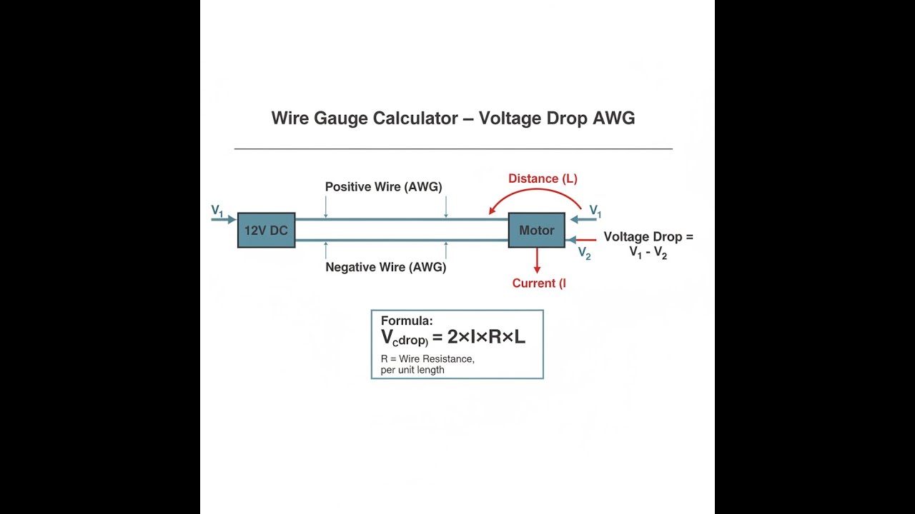
Wire Voltage Drop Diagram

Wire Gauge Voltage Drop Calculator
How to Use This Calculator
This calculator is intended for education, concept evaluation, and preliminary design. Results are based on the equations and assumptions described on this page, but cannot account for every real-world load case, tolerance, material property, environmental condition, installation detail, safety factor, code, or regulatory requirement. Verify all inputs, assumptions, units, and results independently before selecting components or using the result in a real application. Safety-critical, structural, medical, lifting, transportation, or regulated applications must be reviewed by a qualified engineer.
Questions about this calculator or found an error? Message our engineering team.
- Enter the current your load draws in the Current (Amps) field.
- Enter the one-way wire run length in the Distance (Feet) field, then enter your supply voltage in Source Voltage (V).
- Set your acceptable loss threshold in the Max Voltage Drop (%) field — 3% is the recommended starting point for motors and actuators.
- Click Calculate to see your result.
Wire Gauge Voltage Drop Interactive Visualizer
You can see for yourself here how current, wire length, and wire size change your voltage drop. Slide the values and watch what happens. This is an easy way to spot if your wire is too small before anything starts to overheat on your bench.
VOLTAGE DROP
0.64V
DROP PERCENTAGE
5.3%
LOAD VOLTAGE
11.36V
FIRGELLI Automations — Interactive Engineering Calculators
Voltage Drop Equations
Primary Voltage Drop Formula
The standard method for figuring voltage drop is this formula:
The 2x factor is there because electricity has to go out and back—both wires have resistance, and both drop voltage.
Related Calculations
Drop % = (Vdrop ÷ Vsource) × 100
Vload = Vsource - Vdrop
Simple Example
Here’s a real-world case: you have a 12V actuator that draws 10A and sits 20 feet from the power supply. If you run this on 12 AWG wire (resistance = 0.001588 Ω/ft):
- Vdrop = 2 × 10 × 0.001588 × 20 = 0.635V
- Drop % = (0.635 ÷ 12) × 100 = 5.3% — that’s over a 3% guideline
- If you go up to 10 AWG: Vdrop = 2 × 10 × 0.0009989 × 20 = 0.40V (3.3%) — much better
Understanding Wire Gauge and Voltage Drop
What is Voltage Drop?
Voltage drop is what you lose whenever current moves through resistance—every wire has some. Longer wires, or those with a smaller cross-section, have more resistance. That resistance eats up some of your supply voltage before it ever gets to the actuator, with the lost voltage turning into heat. That’s just basic physics.
Motors and actuators are especially sensitive to this. If your 12V actuator gets less than 12V by the time power arrives, expect lower speed and torque, or even a stalled actuator under heavy loads.
Why Wire Gauge Matters
In the AWG system, smaller AWG numbers mean thicker wire, and thicker wire has less resistance per foot. For instance, 12 AWG is about 63% larger in cross-sectional area than 14 AWG, so it has noticeably less resistance. If you’re trying to keep voltage drop within a set limit, using a calculator like this makes finding the right size easier and helps avoid overspending on wire that’s heavier than you need.
The Physics Behind Voltage Drop
The voltage drop comes straight from Ohm’s Law: V = I × R. Wire resistance depends on:
- Material resistivity: Copper is lower than aluminum.
- Length: More length equals more resistance.
- Cross-sectional area: Thicker wire has less resistance.
- Temperature: Hotter wire has more resistance.
The "2" in the voltage drop equation just means you’re adding up both wires—outbound and return—so that’s total resistance.
Worked Example: Linear Actuator Installation
Here's a walk-through for a typical actuator setup. Say your 12V actuator draws 8A at max load and sits 25 feet from the power supply. You want to keep the drop at or below 3% (that’s 0.36V).
Given:
- Current (I) = 8 amps
- Distance (L) = 25 feet
- Source voltage = 12V
- Max voltage drop = 3% = 0.36V
Let's try a few wire sizes:
- 14 AWG: R = 0.002525 Ω/ft, Vdrop = 2 × 8 × 0.002525 × 25 = 1.01V (8.4% - too high)
- 12 AWG: R = 0.001588 Ω/ft, Vdrop = 2 × 8 × 0.001588 × 25 = 0.635V (5.3% - still high)
- 10 AWG: R = 0.0009989 Ω/ft, Vdrop = 2 × 8 × 0.0009989 × 25 = 0.40V (3.3% - a little over)
- 8 AWG: R = 0.0006282 Ω/ft, Vdrop = 2 × 8 × 0.0006282 × 25 = 0.251V (2.1% - passes)
For this case, 8 AWG is needed to stay within 3%. Running smaller wire means your actuator won’t see its expected voltage.
Design Considerations and Best Practices
Voltage Drop Limits
Different loads have different tolerance for voltage drop:
- Motors & actuators (critical): 2-3%
- Lighting/general: 3-5%
- Other loads: Up to 5%
Temperature Derating
As wire temperature goes up (0.4% per °C above 20°C), resistance goes up too. If you're running in a hot area or with many wires bundled together, move up a wire size to compensate for losses due to heat.
Future Load Considerations
If there’s any chance you’ll add to the load later, or re-use the system for something higher power, run a size up now and save the trouble of rewiring.
Applications in Automation Systems
Proper voltage at every actuator is what makes sure your automated system stays synchronized and reliable. Every wire run should be sized for its load and its length. When installing several actuators, check the voltage drop for each branch—not just the main line.
For bigger setups with multiple actuators, calculators like this keep planning straightforward, especially since each wire run will see a different load and length. Take it one branch at a time.
Economic Considerations
Oversized wire isn’t cheap, but over the long term it saves you from nagging issues:
- Lower energy loss (lower heating, longer actuator life)
- No slowdowns or stalls
- Fewer callbacks or troubleshooting for voltage-related failures
- Meets wire code requirements
Safety and Code Compliance
Besides voltage drop, always make sure your chosen wire size also handles the current (ampacity). The National Electrical Code (NEC) lists both voltage drop recommendations and amp limits. Never let your wire get warm under normal use, or you're asking for trouble down the road.
Undersized wire will heat up, damage insulation, or even cause a fire in a bad scenario. Always check both the voltage drop AND the ampacity charts when picking your wire.
Advanced Considerations
If you're dealing with more complex setups, think about:
- AC vs DC: AC runs introduce reactance and skin effect, making real-world impedance a bit harder to estimate.
- Wire metal: Aluminum wire is cheaper but needs to be larger for the same result.
- Conduits/bundling: Bundled wires heat up more, again raising resistance.
- Harmonics: Non-linear loads pull more current than you’d expect from their nameplate rating.
The point is, there’s no single “right” answer for every job—it always depends on your actual loads, distances, and what the system might need in the future. For anything unusual, go through the details rather than guess.
Frequently Asked Questions
📐 Browse all 1000+ Interactive Calculators →
About the Author
Robbie Dickson
Chief Engineer & Founder, FIRGELLI Automations
Robbie Dickson brings over two decades of engineering expertise to FIRGELLI Automations. With a distinguished career at Rolls-Royce, BMW, and Ford, he has deep expertise in mechanical systems, actuator technology, and precision engineering.
🔗 Related Engineering Calculators
More related engineering calculators:
- Cable Sizing Calculator Current and Voltage Drop
- Voltage Divider Calculator
- Wire Ampacity Calculator Nec Table
- Voltage Divider Calculator Output Voltage From Two Resistors
- Voltage Divider ADC Resolution Calculator
- Power Supply Sizing Calculator
- Ohms Law Calculator V I R P
- PWM Duty Cycle Calculator Average Voltage
- Strain Gauge Bridge Output Voltage Calculator
- Motor Torque Calculator Hp Rpm Torque
- Wire Size Calculator — AWG, mm² & Voltage Drop for DC and AC Circuits
Browse all engineering calculators →
Video Walkthrough - How to Use This Calculator
Need to implement these calculations?
Explore the precision-engineered motion control solutions used by top engineers.


