Designing a circuit with multiple resistors connected side by side — rather than end to end — changes how current flows, how resistance adds up, and how heat distributes across your components. Use this Parallel Resistor Calculator to calculate equivalent resistance, branch currents, power dissipation, and conductance using up to 5 resistor values and supply voltage. It matters across electronics prototyping, automotive battery management, and industrial power distribution — anywhere multiple current paths share a common voltage. This page includes the core formulas, a worked engineering example, plain-English theory, and an FAQ.
What is parallel resistance?
Parallel resistance is the combined resistance of 2 or more resistors connected across the same 2 points in a circuit — sharing both voltage but splitting the current. The result is always lower than any single resistor in the group.
Simple Explanation
Think of resistors in parallel like lanes on a highway — adding more lanes lets more traffic through, reducing overall congestion. Each resistor is a separate lane for current, so the more resistors you add in parallel, the easier it is for current to flow — meaning the total resistance drops. The voltage across every lane stays the same; only the current splits up.
📐 Browse all 1000+ Interactive Calculators
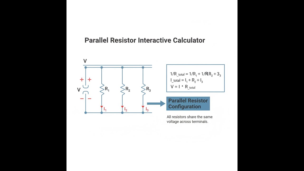
Parallel Resistor Circuit Diagram

Parallel Resistor Interactive Calculator
How to Use This Calculator
- Select your calculation mode from the dropdown — equivalent resistance, branch currents, power dissipation, conductance, or others.
- Enter your resistor values in ohms (Ω) — R1 and R2 are required; R3 through R5 are optional depending on your circuit.
- If your chosen mode requires it, enter the supply voltage in volts (V).
- Click Calculate to see your result.
Parallel Resistor Interactive Visualizer
Watch how adding parallel resistors reduces total resistance while increasing current flow. This animation shows real-time circuit behavior, current distribution, and power dissipation across multiple branches.
EQUIVALENT
54.5Ω
TOTAL CURRENT
220mA
TOTAL POWER
2.64W
CONDUCTANCE
18.3mS
FIRGELLI Automations — Interactive Engineering Calculators
Parallel Resistor Equations & Formulas
Use the formula below to calculate equivalent resistance for parallel resistor networks.
Equivalent Resistance (General Form):
1/Req = 1/R1 + 1/R2 + 1/R3 + ... + 1/Rn
Two Resistors (Product-over-Sum):
Req = (R1 × R2) / (R1 + R2)
Voltage Relationship:
VR1 = VR2 = VR3 = Vsource
Current Division (Ohm's Law):
In = V / Rn
Total Current:
Itotal = I1 + I2 + I3 + ... + In
Power Dissipation in Each Resistor:
Pn = V2 / Rn = In2 × Rn = V × In
Total Conductance:
Gtotal = G1 + G2 + G3 + ... + Gn
where Gn = 1/Rn
Where:
- Req = Equivalent resistance (Ω)
- R1, R2, Rn = Individual resistances (Ω)
- V = Voltage across parallel resistors (V)
- In = Current through resistor n (A)
- Itotal = Total current from source (A)
- Pn = Power dissipated in resistor n (W)
- Gn = Conductance of resistor n (S, siemens)
Simple Example
Three resistors — 100Ω, 200Ω, and 300Ω — connected in parallel across a 12V supply:
- Req = 1 / (1/100 + 1/200 + 1/300) ≈ 54.55Ω
- I₁ = 12V / 100Ω = 120mA, I₂ = 60mA, I₃ = 40mA
- Total current = 220mA
- Total power = 12V × 220mA = 2.64W
Theory & Practical Applications of Parallel Resistor Networks
Parallel resistor configurations form the foundation of current division, load distribution, and impedance matching in electronic systems. Unlike series circuits where current remains constant and voltage divides, parallel circuits maintain constant voltage across all branches while current divides inversely proportional to resistance values. This fundamental property enables critical functions from power supply bus distribution to precision current sources and fault-tolerant redundancy systems.
Fundamental Physics of Parallel Resistance
The reciprocal relationship governing parallel resistance derives directly from Kirchhoff's Current Law (KCL), which states that the algebraic sum of currents entering a node equals zero. At the junction where parallel resistors connect, incoming current Itotal must equal the sum of branch currents. Since each branch experiences identical voltage V and follows Ohm's Law (I = V/R), the total current becomes V(1/R₁ + 1/R₂ + ... + 1/Rₙ). The equivalent resistance Req satisfying Itotal = V/Req yields the reciprocal sum formula.
This conductance-based perspective reveals why parallel resistance always decreases: adding conductance paths (G = 1/R) increases total conductance, reducing equivalent resistance. The equivalent resistance of any parallel combination is always less than the smallest individual resistor—a non-intuitive result for those accustomed to series addition. For two equal resistors R in parallel, Req = R/2; for three, Req = R/3, demonstrating the linear scaling with conductance.
Current Division and Load Sharing
Current distribution in parallel networks follows an inverse relationship to resistance: lower resistance branches draw proportionally higher current. For a two-resistor network, the current through R₁ is I₁ = Itotal × R₂/(R₁ + R₂), showing that R₁'s current depends on the opposite resistor R₂. This cross-coupling effect becomes critical in power distribution systems where load balancing must account for all parallel paths simultaneously.
In high-current applications such as battery discharge systems or motor control, parallel resistors enable current sharing among multiple power devices. A 100A load might use four 0.01Ω sense resistors in parallel (yielding 0.0025Ω equivalent) with each carrying 25A, staying within individual component ratings. However, resistance tolerance creates imbalance—if one resistor measures 0.009Ω and another 0.011Ω, the lower-resistance path carries 11% more current, potentially causing thermal runaway as heating further reduces resistance.
Power Dissipation and Thermal Management
Power dissipation in parallel resistors follows P = V²/R, creating a critical inverse relationship: lower resistance dissipates more power at constant voltage. This contrasts sharply with series circuits where P = I²R makes higher resistance the dominant heat source. In a 12V system with 100Ω and 200Ω resistors in parallel, the 100Ω resistor dissipates 1.44W while the 200Ω dissipates 0.72W—the lower resistance produces twice the heat despite appearing as the "easier" current path.
This property enables deliberate thermal design strategies. Current-sensing shunt resistors use very low values (milliohms) in parallel with load paths specifically to minimize power loss while enabling measurement. Conversely, bleeder resistors across high-voltage capacitors use series-parallel combinations to achieve target resistance while distributing thermal load across multiple physical components, preventing hotspot formation that degrades reliability.
Worked Engineering Example: LED Driver Current Distribution
A 24V LED driver system requires distributing 360mA total current across three parallel LED strings, each with a current-limiting resistor. Each LED string has a forward voltage drop of 18.5V at the operating current. Design the resistor network to achieve equal current distribution and calculate power dissipation.
Step 1: Target current per branch
For equal distribution: Ibranch = 360mA / 3 = 120mA per string
Step 2: Voltage across current-limiting resistors
VR = Vsupply - VLED = 24V - 18.5V = 5.5V
Step 3: Required resistance per branch
Rbranch = VR / Ibranch = 5.5V / 0.120A = 45.83Ω
Nearest standard E24 value: 47Ω (2.5% deviation acceptable for LEDs)
Step 4: Actual current with standard resistor
Iactual = 5.5V / 47Ω = 117.0mA per string
Itotal = 3 × 117.0mA = 351mA
Step 5: Power dissipation per resistor
PR = VR² / R = (5.5V)² / 47Ω = 30.25V² / 47Ω = 0.644W
Select resistors rated for 1W minimum (derating to 65% of maximum)
Step 6: Total system power loss
Presistors = 3 × 0.644W = 1.93W
PLEDs = 3 × (18.5V × 0.117A) = 6.50W
Total power: 8.43W, with 22.9% wasted as resistor heat
Step 7: Tolerance analysis
With 5% tolerance resistors (44.65Ω to 49.35Ω range):
Maximum current: 5.5V / 44.65Ω = 123.2mA (5.3% high)
Minimum current: 5.5V / 49.35Ω = 111.5mA (4.7% low)
Current mismatch between branches: up to 10.5% in worst case
This example demonstrates why precision LED drivers use active current regulation rather than passive resistor networks for critical applications—resistance tolerance creates unacceptable brightness variation in multi-string systems.
Industrial Applications Across Sectors
Power Systems and Distribution: Substation grounding systems employ extensive parallel resistor networks to limit fault current magnitudes during ground faults. A typical 115kV substation might use twenty 0.5Ω resistors in parallel achieving 0.025Ω equivalent resistance, each rated for 50kW momentary power dissipation. The parallel configuration ensures that single-resistor failure doesn't create dangerous overvoltage conditions - one open resistor increases equivalent resistance by only 2.6%, maintaining protective function.
Precision Measurement and Instrumentation: High-precision current shunts for multimeters and oscilloscopes use parallel configurations of matched resistors to achieve target values with superior thermal stability. A 1mΩ shunt might employ four 4mΩ resistors in parallel, each with 1ppm/°C temperature coefficient. Thermal tracking between matched components cancels first-order temperature drift, achieving effective coefficients below 0.2ppm/°C impossible with single-element construction. The four-terminal Kelvin connection separates current and voltage paths, eliminating lead resistance errors.
Automotive Battery Management: Modern electric vehicle battery packs use parallel cell groups to increase capacity while managing failure modes. A Tesla Model 3 battery module contains 46 cells in 2 parallel groups of 23 series cells. If one cell develops high resistance, the parallel connection allows current to bypass through the healthy cell, preventing complete module failure. Cell balancing circuits use parallel resistors across individual cells to dissipate excess charge—a 3.2Ah cell with 50mV imbalance requires 20Ω bleeder resistor dissipating 125mW to equalize over 8 hours.
RF and Microwave Engineering: Parallel resistor networks create precision impedance matching and power division in RF systems. A 50Ω termination for a 75Ω transmission line uses 150Ω and 75Ω resistors in parallel, yielding exactly 50Ω without reactive components that would limit bandwidth. Power combiners for antenna arrays employ parallel quarter-wave transformers with integrated resistors to absorb reflected power from impedance mismatches, maintaining VSWR below 1.5:1 across octave bandwidths.
Test and Burn-in Systems: Semiconductor burn-in systems test thousands of devices simultaneously using parallel load resistors to simulate operating conditions. A typical system might test 512 devices at 100mA each (51.2A total) using a 5V supply. Individual 50Ω load resistors per device would each dissipate 0.5W, but total supply power reaches 256W. Parallel architecture enables per-device current monitoring—any resistor drawing excessive current indicates device failure, triggering automatic bin sorting.
Non-Ideal Behaviors and Practical Limitations
Real resistors exhibit parasitic inductance and capacitance that transform purely resistive networks into complex impedances at high frequencies. A 1000Ω through-hole resistor typically has 10-20nH series inductance, negligible below 1MHz but creating 6-12Ω reactance at 100MHz. When multiple such resistors connect in parallel, inductances combine in parallel (reducing total inductance) while capacitances add—creating resonant circuits with unpredictable impedance peaks. Surface-mount resistors reduce inductance to 0.5-2nH, extending useful frequency range to 500MHz for precision 50Ω terminations.
Thermal effects create dynamic resistance changes that alter current distribution over time. A parallel network designed for equal current sharing at 25°C develops imbalance as components heat at different rates due to airflow patterns or PCB copper distribution. If one resistor in a four-element parallel array runs 20°C hotter than others, its resistance increases by approximately 0.6% (assuming 300ppm/°C coefficient), shifting 0.15% of total current to cooler resistors. Over hours, this creates positive feedback as the hot resistor receives less current, cools slightly, then draws more current again—establishing oscillatory thermal behavior at 0.01-0.1Hz frequencies observable in precision systems.
Voltage coefficient effects in thick-film resistors cause resistance to vary with applied voltage, typically 100-500ppm/V for standard types. In a 1000V divider using parallel networks, 0.05%/V coefficient creates 5% resistance change, completely invalidating simple parallel resistance calculations. Metal film and wirewound types reduce this to below 10ppm/V, essential for high-voltage measurement applications where accuracy depends on voltage-independent resistance.
Optimization Strategies for Robust Design
Achieving precise equivalent resistance requires statistical tolerance analysis beyond simple worst-case bounds. For n resistors in parallel with tolerance σ, the equivalent resistance tolerance follows σeq = σ/√n assuming independent random variations. A 100Ω target using four 400Ω resistors with 1% tolerance yields 0.5% equivalent tolerance—but only if resistors come from different manufacturing lots ensuring uncorrelated variation. Purchasing from a single reel often provides correlated tolerance where all resistors skew high or low together, eliminating statistical improvement.
Current derating in parallel configurations requires calculating individual power dissipation, not simply dividing total power by resistor count. In a network where one resistor is 10% low and another 10% high (within tolerance), the low resistor dissipates 22% more power than the high resistor at constant voltage—requiring 1.5× derating factor instead of the naive 1.0× assumption. Conservative designs use 50% derating (2× safety margin) for all parallel resistors in power applications.
For more complex circuit analysis and design resources, visit our comprehensive engineering calculator library, offering specialized tools for series-parallel networks, voltage dividers, and power distribution systems.
Frequently Asked Questions
Free Engineering Calculators
Explore our complete library of free engineering and physics calculators.
Browse All Calculators →🔗 Explore More Free Engineering Calculators
- Wheatstone Bridge Calculator
- Resistor Color Code Calculator
- Low-Pass RC Filter Calculator — Cutoff Frequency
- Capacitor Charge Discharge Calculator — RC Circuit
- Bridge Rectifier Calculator
- Eirp Calculator
- Resistor Noise Calculator
- Voltage Divider Calculator
- Voltage Divider & ADC Resolution Calculator
- Transformer Turns Ratio Calculator
About the Author
Robbie Dickson — Chief Engineer & Founder, FIRGELLI Automations
Robbie Dickson brings over two decades of engineering expertise to FIRGELLI Automations. With a distinguished career at Rolls-Royce, BMW, and Ford, he has deep expertise in mechanical systems, actuator technology, and precision engineering.
Need to implement these calculations?
Explore the precision-engineered motion control solutions used by top engineers.


