When polarized light goes through a second filter, the intensity you get out depends only on the angle between the two filter axes. This Malus Law Calculator will give you the transmitted light intensity, filter angle, incident intensity, polarization efficiency, or intensity ratio using Malus's Law (I = I₀ cos²θ). You'll see this principle show up in LCD display optics, optical fiber comms, and stress analysis using polarized light. You'll find the main formula, an actual LCD calculation, and some practical notes and questions further down.
What is Malus's Law?
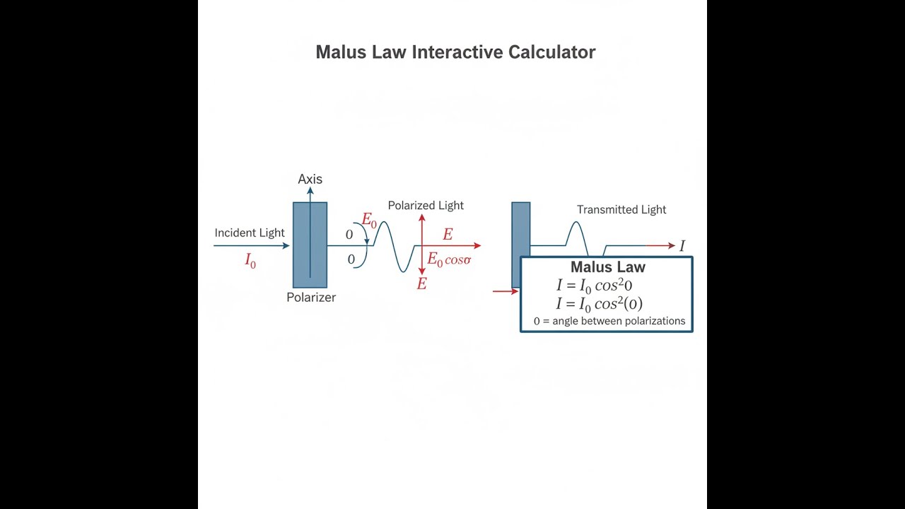
Malus's Law is a simple relationship for how much linearly polarized light makes it through a second polarizer. As you rotate this second filter, the amount of light transmitted peaks when both filters are lined up and drops off smoothly to near zero when the axes are 90° apart (crossed).
Simple Explanation
If you visualize polarized light as straight waves, think of the filter as like a set of bars or slats. When the waves line up with the bars, they get through. Rotating the filter means fewer waves line up, so less gets through. By the time you're at 90°, nothing gets through except a tiny bit due to imperfections. The curve is always cos²θ with angle.
📐 Browse all 1000+ Interactive Calculators
Malus Law Diagram

Malus Law Calculator
How to Use This Calculator
This calculator is intended for education, concept evaluation, and preliminary design. Results are based on the equations and assumptions described on this page, but cannot account for every real-world load case, tolerance, material property, environmental condition, installation detail, safety factor, code, or regulatory requirement. Verify all inputs, assumptions, units, and results independently before selecting components or using the result in a real application. Safety-critical, structural, medical, lifting, transportation, or regulated applications must be reviewed by a qualified engineer.
Questions about this calculator or found an error? Message our engineering team.
- Select your calculation mode from the dropdown — choose what you want to solve for (transmitted intensity, angle, incident intensity, polarization efficiency, or intensity ratio).
- Enter the incident intensity (I₀) in W/m² and/or the angle θ in degrees, depending on the selected mode.
- If solving for angle, enter both incident and transmitted intensity values instead.
- Click Calculate to see your result.
Malus Law Interactive Visualizer
Rotate the analyzer and you'll see the transmitted intensity follow the cos²θ relationship, dropping to nearly zero at 90° for crossed polarizers.
TRANSMITTED INTENSITY
75.0 W/m²
TRANSMISSION
75.0%
COS²(θ) FACTOR
0.750
FIRGELLI Automations — Interactive Engineering Calculators
Malus Law Equations
The standard equation below gives you transmitted light intensity for a polarizing filter at angle θ from original polarization.
Fundamental Malus Law
Where:
- I = transmitted light intensity (W/m²)
- I₀ = incident polarized light intensity (W/m²)
- θ = angle between incident polarization direction and polarizer transmission axis (degrees or radians)
Angle from Intensity Ratio
Valid Range:
- 0 ≤ I/I₀ ≤ 1 (transmitted intensity cannot exceed incident)
- 0° ≤ θ ≤ 90° (principal range for polarizer orientation)
Electric Field Relationship
Intensity-Field Connection:
- E = transmitted electric field amplitude (V/m)
- E₀ = incident electric field amplitude (V/m)
- Since I ∝ E², the intensity follows cos² dependence
Transmission Efficiency
Special Cases:
- θ = 0°: T = 100% (parallel polarizers, maximum transmission)
- θ = 45°: T = 50% (half intensity transmitted)
- θ = 90°: T = 0% (crossed polarizers, complete extinction)
Simple Example
Start with polarized light at 100 W/m² and set the filter to 45°.
I = 100 × cos²(45°) = 100 × 0.5 = 50 W/m² out.
Transmission is 50%. Electric field ratio is cos(45°) = 0.7071.
Theory & Practical Applications
Physical Foundation of Malus Law
Malus Law just tells you the drop in intensity when linearly polarized light passes through a polarizer at angle θ. What’s really happening is only the electric field component lined up with the polarizer gets through. So you get E = E₀ cos(θ). Since intensity goes as E squared, you get the cos²(θ) in your output. This is only exact for perfect polarizers and clean, single-wavelength, fully polarized light. In the real world, polarizer extinction (how well it blocks) is usually limited – sheet film polarizers might hit 1000:1, prisms can break 1,000,000:1 if you pay for it. If your light isn’t perfectly polarized, you’ll need more complicated math (like Stokes parameters). Absorption loss, scattering, angle of incidence, and changing the wavelength with white light can all affect what you actually measure.
The law stops working right if your polarizer is leaking more than expected at 90°, or if you’ve got partly polarized (or unpolarized) input. Any real filter will leak a little at 90°. If your source isn’t a single spot beam but has a wide spread or multiple wavelengths, expect deviations from the ideal formula.
Polarization States and Coordinate Systems
Polarization describes the electric field's direction—always perpendicular to the direction the light is traveling. Linear polarization is just the special case where the direction is fixed; you can always describe that direction as some angle with respect to a reference axis. In multi-polarizer setups, every new polarizer “sets” a new angle—filters that are 90° apart basically block everything, but throwing in a middle filter at another angle can re-orient the polarization and let some light through, following Malus Law each time. If you stick with the linear case, it’s just chaining cos² factors for each step.
Things like circular and elliptical polarization are harder. For instance, circular light going through a linear polarizer always gives you half the original intensity, no matter the orientation, because you’re just splitting the energy evenly between two perpendicular directions. This matters in applications where orientation changes, since you get consistent output with circular polarization. Quarter-wave plates are used to convert linear to circular and vice versa, letting you control polarization for certain measurement or communication purposes.
Real-World Engineering Applications
LCDs rely directly on Malus Law. You start with unpolarized light, filter it (only half passes through), rotate the polarization using liquid crystal (the amount depends on applied voltage), and finally set the output with a second polarizer. With crossed setup, maximum light is transmitted when the liquid crystal rotates the polarization by 90°, minimum when no rotation happens. LCD design is always balancing transmission losses, extinction, and panel geometry. In IPS designs, the liquid crystal is steered sideways rather than “twisting”, for improved color and viewing angles.
Photoelastic stress analysis relies on mechanical stress causing changes in polarization (birefringence). Place your sample between crossed polarizers, and only stressed zones twist the polarization enough to light up. This method directly shows you stress concentrations in plastics, glass, and composite parts that are otherwise completely invisible—no simulation required. Aerospace models often use coating and this technique in wind tunnel testing to reveal where stress hot spots are during real loading.
In fiber optics, engineers use polarization for two channels on the same wavelength (polarization-division multiplexing), essentially doubling the data rate. But environmental variation changes polarization as light travels, causing loss and crosstalk—polarization controllers are used to keep alignment, making sure maximum signal gets through. As speeds and distances go up, managing polarization effects becomes more important, especially over tens of kilometers of cable at 10 Gb/s and above.
Photography and Variable Neutral Density Filters
Stacking two polarizers lets photographers make a variable ND filter. Rotate one, and you reduce transmission smoothly by Malus Law. Real-world losses (surface reflections, imperfect blocking) limit minimum transmission, but it’s still adjustable over several stops. These filters are excellent for video and shooting wide open in bright light, but can give uneven color or dark bands if your scene already has polarized light (like blue skies or reflections off water).
For basic glare reduction, landscape photographers often use one polarizer. Point it at glass or water at the right angle (Brewster’s angle), rotate for minimum reflection, and you’ll get a notable color boost and much less glare. The efficiency depends on wavelength—blue light polarizes more than red in the sky—so you can see weird color shifts if you push it too far, especially with wide-angle lenses.
Quantum Mechanics and Photon Polarization
On the quantum side, Malus Law appears as a probability. A photon polarized at angle α heading into a polarizer at angle θ only passes with probability cos²(θ – α). It either goes through completely or not at all. When you look at a lot of photons, the stats add up to the classical formula. This single-photon behavior is used for quantum cryptography, where the randomness and “no peeking” nature of polarization-based measurements make eavesdropping detectable.
Entangled photons can be sent to separated detectors with polarizers at different angles; the coincidence rate follows a cosine-squared rule modified for both analyzers. These experiments confirm the quantum predictions and are foundational for secure communication systems exploiting the nature of photon polarization.
Worked Example: LCD Optical Design
Problem: LCD pixel design with these specs: backlight intensity I₀ = 850 cd/m², first polarizer transmits 42%, LC cell rotates polarization up to 88°, second polarizer is crossed at 90°. Figure out (a) max pixel brightness, (b) minimum, (c) required angle for 30% of max, and (d) actual contrast ratio limited by extinction.
Solution:
(a) Max brightness (max LC rotation, 90°):
After the first polarizer: I₁ = 0.42 × 850 cd/m² = 357 cd/m²
Full 90° rotation aligns light with output polarizer: I_max = 357 × cos²(0°) × 0.42 = 357 × 1 × 0.42 = 149.94 cd/m²
So, about 150 cd/m²
(b) Min brightness (no LC rotation, still crossed):
Still 357 cd/m² after first polarizer, but polarization is now perpendicular to second: I_min,ideal = 357 × cos²(90°) = 0 cd/m²
But, real polarizers miss perfect extinction. With ER = 2000:1, minimum output I_min ≈ 150 / 2000 = 0.075 cd/m²
This treats extinction as the limiting floor.
(c) Find rotation angle for 30% max brightness:
Target output: I_target = 0.30 × 150 = 45 cd/m²
Set up: 45 = 357 × cos²(θ) × 0.42 ⇒ cos²(θ) = 45 / 149.94 = 0.3001,
cos(θ) = 0.5478 ⇒ θ = arccos(0.5478) ≈ 56.8°
The LC needs to rotate from the crossed state by 56.8°, or, as difference from full rotation, 33.2° less than maximum
(d) Actual contrast ratio:
CR = I_max / I_min = 150 / 0.075 = 2000:1
So in practice, contrast ratio is capped by the extinction ratio. If you need better, you need better polarizers and possibly extra compensating layers.
Engineering insight: The numbers above are for the optical stack under ideal test conditions. In the real world, LCD contrast is often worse because of stray light, backlight bleed, reflections inside the display, and ambient lighting. For consumer devices, you might see contrast in the 500:1 to 800:1 range. More sophisticated panels use technologies like local dimming to boost this for HDR applications—those methods work by dimming parts of the backlight, not by relying on better polarizers alone.
Limitations and Practical Considerations
Malus Law only applies for ideally polarized, non-diverging, monochromatic light and perfect polarizers. Real light sources often have angle spread and extra wavelengths, so each ray might hit the filter at a different effective angle and not follow cos²θ exactly. This angular divergence, along with different reflection coefficients for different polarization directions at the filter surface, explains why measured results often differ from the formula away from normal incidence. System designers building with multiple optics elements or at large angles should expect to use ray tracing or matrix methods for real transmission predictions.
Temperature changes will affect both liquid crystal and polarizer properties, shifting transmission and rotation angles in displays. Automotive LCDs have to account for this over a wide thermal range, usually by sensor feedback and tweaking drive voltages, or by picking special materials. Laser and other high-power setups might create thermal gradients in polarizers, inducing unwanted birefringence and diminishing extinction. Engineers needing stable polarization over fiber runs use specialized stress structures or asymmetric cores in fiber to keep polarization rotation to a minimum.
Frequently Asked Questions
▼ What happens when unpolarized light passes through a polarizer?
▼ Why do two crossed polarizers block light, but adding a third at 45° allows transmission?
▼ How does wavelength affect Malus Law measurements?
▼ Can Malus Law predict transmission through partially polarized light?
▼ What is the extinction ratio and how does it limit practical applications?
▼ How does Malus Law apply to optical fiber communication systems?
Free Engineering Calculators
Explore our complete library of free engineering and physics calculators.
Browse All Calculators →🔗 Explore More Free Engineering Calculators
About the Author
Robbie Dickson — Chief Engineer & Founder, FIRGELLI Automations
Robbie Dickson brings over two decades of engineering expertise to FIRGELLI Automations. With a distinguished career at Rolls-Royce, BMW, and Ford, he has deep expertise in mechanical systems, actuator technology, and precision engineering.
Video Walkthrough - How to Use This Calculator
Need to implement these calculations?
Explore the precision-engineered motion control solutions used by top engineers.


