Choosing the wrong inductor for an AC circuit — or ignoring how frequency changes its behavior — leads to filter failures, power factor penalties, and circuit instability. Use this Inductive Reactance Calculator to calculate XL, inductance, frequency, total impedance, circuit current, or quality factor using frequency, inductance, resistance, and voltage inputs. It matters in filter design, power factor correction, and RF transmission systems where phase relationships directly affect efficiency and stability. This page includes the governing formulas, a worked three-phase motor example, full theory, and an FAQ covering core material effects, parasitic behavior, and multi-inductor circuits.
What is inductive reactance?
Inductive reactance is the opposition an inductor creates against alternating current, measured in ohms. Unlike resistance, it doesn't dissipate energy as heat — it scales with frequency, so the higher the frequency, the harder the inductor pushes back against current flow.
Simple Explanation
Think of an inductor like a flywheel — it resists sudden changes in motion (current). The faster you try to spin it back and forth (higher frequency), the harder it resists. A slow back-and-forth barely bothers it, but rapid reversals create strong opposition. That opposition is inductive reactance.
📐 Browse all 1000+ Interactive Calculators
How to Use This Calculator
- Select a calculation mode from the dropdown — choose what you want to solve for (reactance, inductance, frequency, impedance, current, or quality factor).
- Enter the required input values in the fields that appear — frequency in Hz, inductance in H, resistance in Ω, or voltage in V depending on the mode.
- Check your values are positive and non-zero where required — the calculator will prompt you if something is invalid.
- Click Calculate to see your result.
Circuit Diagram

Interactive Calculator
📹 Video Walkthrough — How to Use This Calculator
Inductive Reactance Interactive Visualizer
Watch how frequency and inductance control AC circuit opposition in real-time. See the phase relationship between voltage and current as inductive reactance changes with your inputs.
REACTANCE XL
37.7 Ω
CURRENT
3.18 A
PHASE ANGLE
90°
FIRGELLI Automations — Interactive Engineering Calculators
Governing Equations
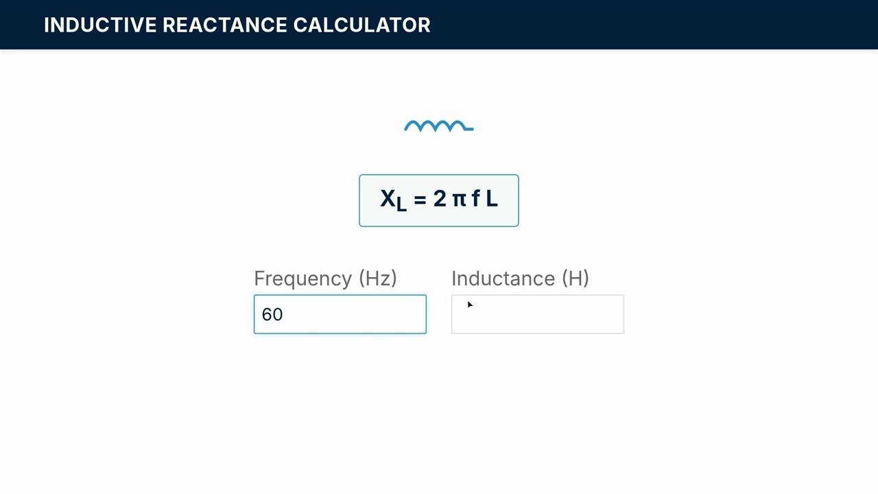
Use the formula below to calculate inductive reactance.
Inductive Reactance
XL = 2πfL = ωL
Where:
- XL = Inductive reactance (Ω, ohms)
- f = Frequency (Hz, hertz)
- L = Inductance (H, henries)
- �� = Angular frequency = 2πf (rad/s, radians per second)
Use the formula below to calculate total impedance in an R-L circuit.
Total Impedance (R-L Circuit)
Z = √(R² + XL²)
θ = arctan(XL / R)
Where:
- Z = Total impedance magnitude (Ω)
- R = Resistance (Ω)
- θ = Phase angle (degrees or radians, current lags voltage)
Use the formula below to calculate current and reactive power.
Current and Power Relationships
I = V / XL
Q = V × I = V² / XL
Where:
- I = RMS current (A, amperes)
- V = RMS voltage (V, volts)
- Q = Reactive power (VAR, volt-amperes reactive)
Use the formula below to calculate the quality factor of an inductor.
Quality Factor
Q = XL / Rcoil = ωL / Rcoil
Where:
- Q = Quality factor (dimensionless)
- Rcoil = Coil winding resistance (Ω)
Simple Example
Given: frequency = 60 Hz, inductance = 0.1 H
XL = 2π × 60 × 0.1 = 37.7 Ω
Angular frequency ω = 2π × 60 = 376.99 rad/s
At 60 Hz, this inductor opposes AC current with 37.7 ohms of reactance.
Theory & Practical Applications
Physical Mechanism of Inductive Reactance
Inductive reactance emerges from Faraday's law of electromagnetic induction, where a time-varying current through a coil generates a changing magnetic flux that induces a counter-electromotive force opposing the current change. This self-induced voltage, proportional to the rate of current change (dI/dt), manifests as an effective impedance that increases linearly with frequency. Unlike resistive dissipation that converts electrical energy to heat, inductive reactance stores energy temporarily in the magnetic field during one quarter-cycle and returns it to the circuit during the next quarter-cycle, resulting in a 90° phase lag between current and voltage waveforms.
The frequency dependence of XL = 2πfL reveals that at DC (f = 0), an ideal inductor presents zero reactance—effectively a short circuit—while at very high frequencies, reactance approaches infinity, making the inductor behave as an open circuit. This frequency-selective behavior makes inductors fundamental to filter design, where they pass low frequencies while blocking high frequencies. Real-world inductors deviate from ideality due to parasitic winding resistance (ESR), inter-turn capacitance, and core losses in ferromagnetic materials. At frequencies approaching the self-resonant frequency (typically 1-100 MHz for power inductors), parasitic capacitance dominates and the component begins behaving capacitively—a critical failure mode in RF applications that engineers must anticipate through careful component selection.
Power Factor Correction in Industrial Systems
Industrial facilities containing large induction motors, transformers, and arc furnaces typically operate at power factors between 0.65 and 0.85 lagging due to high inductive reactance. Utilities penalize poor power factor because it requires higher current delivery for the same real power, increasing transmission losses and requiring oversized infrastructure. A 500 HP induction motor drawing 400 A at 480 V three-phase with a power factor of 0.75 delivers 249 kW of real power but demands 332 kVA of apparent power. The reactive component (223 kVAR) circulates uselessly between the utility and the motor's magnetic field.
Power factor correction capacitors counteract inductive reactance by supplying leading reactive power locally, reducing the reactive burden on utility feeders. The required capacitance for a target power factor follows from the reactive power triangle: Qcap = P(tan θ1 - tan θ2), where P is real power, θ1 is the initial power factor angle, and θ2 is the target angle. For our motor example, correcting from 0.75 to 0.95 power factor requires Qcap = 249(tan(41.4°) - tan(18.2°)) = 249(0.882 - 0.329) = 138 kVAR of capacitive compensation. At 480 V, this demands C = Q/(2πfV²) = 138,000/(2π×60×480²) = 1590 μF per phase. A critical non-obvious constraint: motor starting current transients can excite resonances between correction capacitors and system inductance, potentially generating voltage spikes exceeding 2.0 per-unit that damage insulation. Properly designed systems include series reactors (typically 6-7% reactance) to detune resonances below the 5th harmonic.
Filter Design and Cutoff Frequency Determination
Low-pass RL filters attenuate high-frequency signals while passing low frequencies, with cutoff frequency fc = R/(2πL) where output voltage falls to 0.707 of input (−3 dB point). Consider designing a filter to remove 120 Hz ripple from a DC power supply while preserving the DC component and minimizing voltage drop across the series inductor. Specifying Rload = 100 Ω and targeting fc = 20 Hz for adequate 120 Hz attenuation yields L = R/(2πfc) = 100/(2π×20) = 0.796 H.
At 120 Hz, the inductive reactance XL = 2π(120)(0.796) = 601 Ω. The attenuation factor is 20log₁₀(R/√(R² + XL²)) = 20log₁₀(100/609) = −15.7 dB, reducing 120 Hz ripple amplitude by a factor of 6.09. However, the DC resistance of 0.796 H wound with AWG 20 copper wire (approximately 1600 turns on an EI core) typically measures 18-25 Ω, causing 18-25% voltage loss under load—unacceptable for many applications. This reveals a fundamental inductor design tradeoff: achieving high inductance requires many turns, but more turns increase winding resistance, degrading DC efficiency. Engineers resolve this through core material selection (ferrite for high permeability enabling fewer turns) and wire gauge optimization (larger wire reduces resistance but limits available turns in fixed geometry). Modern switch-mode power supplies sidestep this issue entirely by operating at 50-500 kHz where much smaller inductance values (tens of microhenries) provide equivalent filtering with minimal DC resistance.
Worked Example: Three-Phase Motor Feeder Design
Design the feeder circuit for a 75 HP (55.9 kW), 460 V three-phase induction motor operating at 92% efficiency and 0.84 power factor lagging. Calculate conductor impedance, voltage drop, and required power factor correction to achieve 0.96 system power factor.
Step 1: Calculate Motor Current
Output power Pout = 75 HP × 746 W/HP = 55,950 W
Input power Pin = 55,950 / 0.92 = 60,815 W
Line current I = Pin / (√3 × VL × PF) = 60,815 / (√3 × 460 × 0.84) = 88.3 A RMS
Step 2: Determine Feeder Impedance
Using 250 kcmil copper conductors (300 ft run), reference tables give R = 0.0515 Ω/1000 ft and XL = 0.0435 Ω/1000 ft at 60 Hz.
Total resistance per phase: Rtotal = (0.0515)(300/1000) = 0.01545 Ω
Total reactance per phase: XL,total = (0.0435)(300/1000) = 0.01305 Ω
Step 3: Calculate Voltage Drop
Resistive drop: Vdrop,R = I × R × cos(θ) = 88.3 × 0.01545 × 0.84 = 1.146 V
Reactive drop: Vdrop,X = I × XL × sin(θ) = 88.3 × 0.01305 × 0.540 = 0.621 V
Total drop: Vdrop = √(1.146² + 0.621²) = 1.303 V per phase
Percentage drop = (1.303/460) × 100 = 0.283% (excellent, well below 3% NEC recommendation)
Step 4: Power Factor Correction Calculation
Real power P = 60,815 W
Initial apparent power S1 = P / PF1 = 60,815 / 0.84 = 72,399 VA
Initial reactive power Q1 = S1 × sin(acos(0.84)) = 72,399 × 0.5418 = 39,230 VAR
Target reactive power Q2 = P × tan(acos(0.96)) = 60,815 × 0.2917 = 17,740 VAR
Required capacitive compensation: Qcap = 39,230 - 17,740 = 21,490 VAR
Step 5: Capacitor Sizing
For three-phase delta-connected capacitors at 460 V:
Cper phase = Qcap / (3 × 2π × f × VL²) = 21,490 / (3 × 2π × 60 × 460²) = 89.7 μF
Standard rating: Select 100 μF, 480 V capacitors (three units in delta configuration)
Actual correction: Qactual = 3 × 2π(60)(100×10⁻⁶)(460²) = 23,966 VAR
Corrected power factor: PFnew = 60,815 / √(60,815² + (39,230-23,966)²) = 0.971
This example demonstrates that power factor correction reduces feeder current from 88.3 A to 72.4 A (18% reduction), decreasing I²R losses by 32% and deferring infrastructure upgrades. The non-obvious engineering insight: capacitors must be sized for continuous operation at 135% rated reactive power per IEEE 18-2012 due to harmonic voltage distortion and overvoltage conditions, effectively requiring 120-130 μF units rather than the calculated 100 μF. Additionally, contactor switching must be coordinated with motor starting to prevent transient overvoltages from capacitor-energized motor deceleration.
High-Frequency Parasitic Effects
Above approximately 1 MHz, parasitic effects dominate inductor behavior. Inter-turn capacitance Cpar, typically 5-50 pF for air-core coils and 50-500 pF for ferrite-core inductors, creates a self-resonant frequency fres = 1/(2π√(LCpar)) where the component transitions from inductive to capacitive. A 10 μH inductor with 30 pF parasitic capacitance resonates at fres = 1/(2π√(10×10⁻⁶ × 30×10⁻¹²)) = 9.19 MHz. Operating an inductor near fres produces extreme impedance values—both very high at resonance and potentially negative (capacitive) above resonance—causing circuit instability, oscillation, and EMI generation.
RF engineers mitigate parasitics through distributed winding techniques (basket weave, bank winding) that minimize turn-to-turn capacitance, ferrite material selection optimized for frequency range (67 material for 1-30 MHz, 43 material for 50-200 MHz), and deliberate damping networks. In precision applications like LC oscillators and impedance matching networks, engineers specify inductors with Q values exceeding 100 at the operating frequency and measure self-resonance explicitly, rejecting components where fres is less than 5× the operating frequency. This conservative margin ensures reactance remains predictably inductive across temperature variations and component tolerances. For more information on related electrical calculations, visit our engineering calculator hub.
Frequently Asked Questions
Why does inductive reactance increase linearly with frequency while capacitive reactance decreases? +
How do core materials affect inductor reactance at different frequencies? +
What causes the 90-degree phase relationship between voltage and current in inductors? +
Can inductive reactance ever exceed the impedance magnitude in an RL circuit? +
How does DC bias current affect AC inductive reactance measurements? +
What determines whether parallel or series reactance formulas apply in multi-inductor circuits? +
Free Engineering Calculators
Explore our complete library of free engineering and physics calculators.
Browse All Calculators →🔗 Explore More Free Engineering Calculators
- Wheatstone Bridge Calculator
- Capacitor Charge Discharge Calculator — RC Circuit
- I2C Pull-Up Resistor Calculator
- Resistor Color Code Calculator
- Joule Heating Calculator
- Capacitive Reactance Calculator
- Lc Filter Calculator
- Voltage Divider Calculator
- Transformer Turns Ratio Calculator
- Voltage Divider Calculator — Output Voltage from Two Resistors
About the Author
Robbie Dickson — Chief Engineer & Founder, FIRGELLI Automations
Robbie Dickson brings over two decades of engineering expertise to FIRGELLI Automations. With a distinguished career at Rolls-Royce, BMW, and Ford, he has deep expertise in mechanical systems, actuator technology, and precision engineering.
Need to implement these calculations?
Explore the precision-engineered motion control solutions used by top engineers.


