Designing AC circuits without knowing your capacitive reactance is guesswork — and guesswork causes filter failures, power factor penalties, and blown components. Use this Capacitive Reactance Interactive Calculator to calculate XC, capacitance, frequency, total impedance, AC current, or phase angle using frequency, capacitance, resistance, and voltage inputs. It matters in power electronics, audio engineering, and RF communications — anywhere a capacitor interacts with an AC signal. This page includes the core formula, a worked multi-part engineering example, full theory, and an FAQ covering real-world behavior.
What is Capacitive Reactance?
Capacitive reactance is the opposition a capacitor presents to alternating current. The higher the frequency of the AC signal — or the larger the capacitor — the less it resists current flow.
Simple Explanation
Think of a capacitor like a spring in a water pipe. At low flow rates (low frequency), the spring resists movement and blocks flow. At high flow rates (high frequency), the spring barely has time to push back, so water moves through easily. That's exactly how a capacitor behaves with electrical current — easy at high frequencies, resistant at low ones.
📐 Browse all 1000+ Interactive Calculators
Circuit Diagram

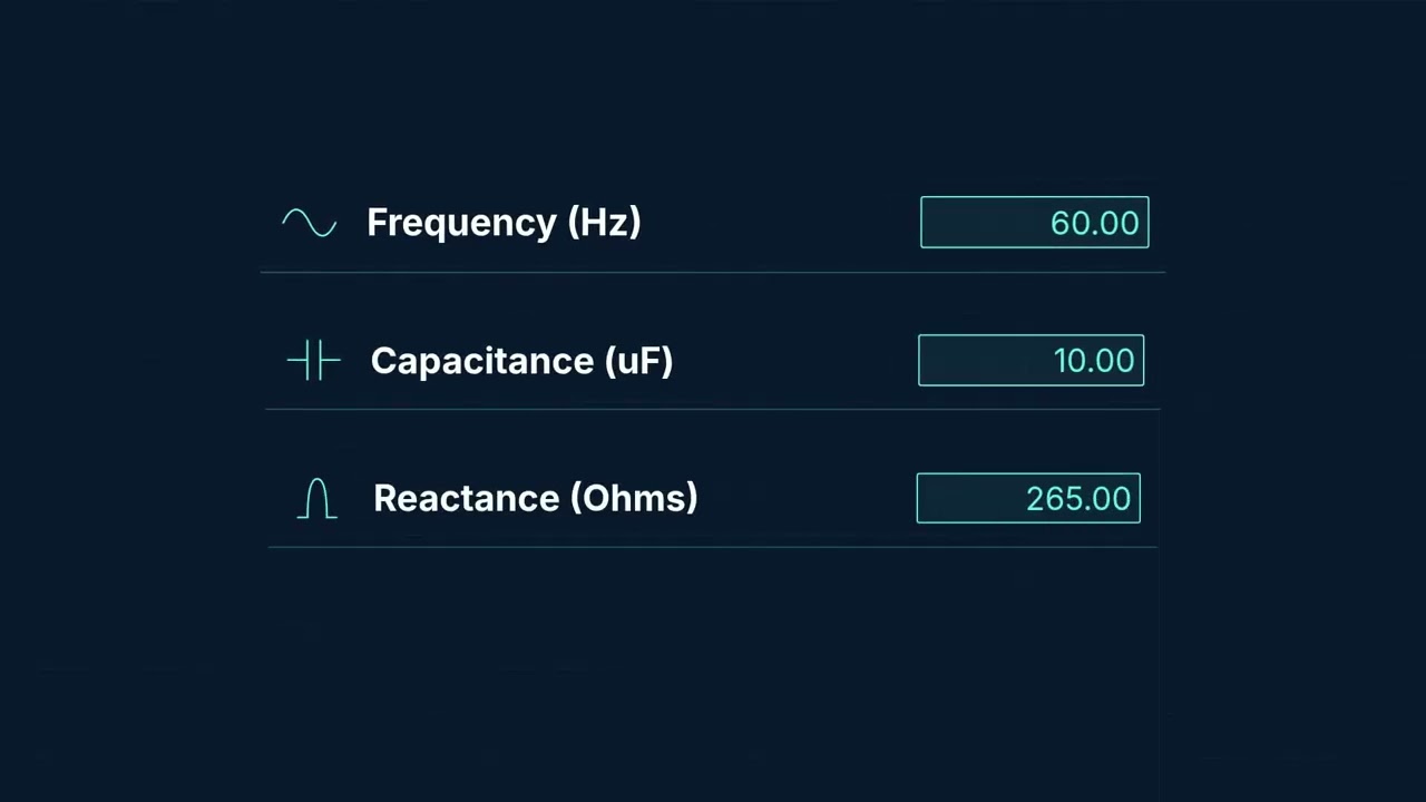
Interactive Calculator
How to Use This Calculator
- Select your Calculation Mode from the dropdown — choose what you want to solve for (reactance, capacitance, frequency, impedance, current, or phase angle).
- Enter the required input values: frequency (Hz), capacitance (μF), resistance (Ω), or voltage (V) — the calculator shows only the fields you need for the selected mode.
- Check your values are positive and non-zero where required — frequency and capacitance must always be greater than zero.
- Click Calculate to see your result.
📹 Video Walkthrough — How to Use This Calculator
Capacitive Reactance Interactive Visualizer
Watch how capacitor reactance changes with frequency and capacitance in real-time. Adjust the sliders to see the frequency response curve and vector diagram showing phase relationships.
REACTANCE XC
26.5 Ω
IMPEDANCE Z
56.6 Ω
PHASE ANGLE
-28.1°
FIRGELLI Automations — Interactive Engineering Calculators
Equations & Variables
Use the formula below to calculate capacitive reactance.
Fundamental Capacitive Reactance
XC = 1 / (2πfC)
XC = Capacitive reactance (Ω, ohms)
f = Frequency (Hz, hertz)
C = Capacitance (F, farads)
π = Pi (approximately 3.14159)
RC Series Impedance
Z = √(R² + XC²)
Z = Total impedance magnitude (Ω, ohms)
R = Resistance (Ω, ohms)
XC = Capacitive reactance (Ω, ohms)
Phase Angle and Power Factor
θ = -arctan(XC / R)
PF = cos(θ)
θ = Phase angle (degrees or radians, negative for capacitive)
PF = Power factor (dimensionless, 0 to 1)
Note: Negative phase angle means current leads voltage
AC Current Calculation
I = V / Z
I = AC current magnitude (A, amperes)
V = Applied AC voltage (V, volts RMS)
Z = Total circuit impedance (Ω, ohms)
Simple Example
Given: Frequency = 60 Hz, Capacitance = 100 μF
XC = 1 / (2π × 60 × 100×10-6) = 26.53 Ω
With R = 50 Ω: Z = √(50² + 26.53²) = 56.60 Ω
At 120 V: I = 120 / 56.60 = 2.12 A
Theory & Practical Applications
Fundamental Physics of Capacitive Reactance
Capacitive reactance quantifies the opposition a capacitor presents to alternating current flow, arising from the capacitor's ability to store and release electrical charge. Unlike resistance, which dissipates energy as heat, capacitive reactance represents energy storage in the electric field between the capacitor's plates. The inverse relationship between reactance and frequency (XC = 1/(2πfC)) reveals a critical non-obvious behavior: capacitors act as open circuits at DC (f = 0, XC → ∞) but approach short circuits at extremely high frequencies (f → ∞, XC → 0). This frequency-dependent behavior makes capacitors indispensable for filtering, coupling, and energy storage applications across the electromagnetic spectrum.
The phase relationship in capacitive circuits defies simple intuition. In a pure capacitive load, current leads voltage by exactly 90°, meaning the current reaches its peak one-quarter cycle before the voltage. This occurs because the capacitor must be charged before voltage can build across its terminals — the charging current flows first, then voltage accumulates. In practical RC circuits, the phase angle falls between 0° (purely resistive) and -90° (purely capacitive), with the arctangent relationship determining the exact value. This phase shift has profound implications for power factor correction, where capacitors compensate for the lagging current in inductive loads to minimize reactive power draw from utility grids.
Non-Ideal Behavior and Practical Limitations
Real capacitors exhibit parasitic effects that deviate from ideal reactance calculations, particularly at high frequencies. Every physical capacitor possesses equivalent series resistance (ESR) and equivalent series inductance (ESL), transforming the simple reactance into a complex impedance with frequency-dependent characteristics. Above the self-resonant frequency (SRF), where ESL reactance equals capacitive reactance, the capacitor behaves inductively rather than capacitively — a critical failure mode in RF and power supply filtering applications. Film capacitors typically exhibit SRF in the MHz range, while ceramic capacitors can maintain capacitive behavior into the GHz range, making capacitor selection highly application-specific.
Temperature and voltage bias significantly alter capacitance values in ceramic capacitors, particularly those using high-permittivity dielectrics like X7R and Y5V formulations. A 10 μF X7R capacitor rated at 25V may drop to 6 μF when operating at 20V DC bias, reducing its effectiveness at the designed reactance by nearly 40%. This voltage coefficient of capacitance creates unexpected impedance increases in DC-DC converter output stages and audio coupling circuits. Designers must derate ceramic capacitors or specify more stable dielectrics like C0G/NP0 for precision timing and filter applications where reactance accuracy matters. For more comprehensive electrical system analysis, see the complete engineering calculator collection.
Power Electronics and Motor Drive Applications
In three-phase industrial power systems, capacitor banks provide reactive power compensation to improve power factor and reduce demand charges. A manufacturing facility drawing 500 kW at 0.75 power factor requires 441 kVAR of reactive power, which utility companies must generate and transmit. Installing capacitor banks to raise power factor to 0.95 reduces reactive demand to 164 kVAR, cutting transmission losses and avoiding power factor penalties. The capacitor bank reactance must be carefully calculated for the system's 50 Hz or 60 Hz frequency, with typical values ranging from 2-10 Ω per phase at industrial voltage levels. Overcorrection can lead to leading power factor, which also incurs penalties and can cause voltage rise issues during light-load conditions.
Variable frequency drive (VFD) DC bus capacitors experience extreme stress from high-frequency ripple currents superimposed on DC voltage. A 480V three-phase drive operating at 10 kHz switching frequency subjects the DC bus capacitor to ripple currents at 6× line frequency (360 Hz for 60 Hz input) plus switching harmonics. The capacitor must present low impedance across this frequency range to absorb ripple without excessive voltage deviation. Film capacitors with ESR below 10 mΩ and current ratings exceeding 50 A RMS are common in 50 kW drives, selected not just for capacitance but for their low reactance at ripple frequencies.
Audio and Signal Processing Applications
AC coupling capacitors in audio amplifier stages block DC bias while passing audio signals, with the coupling capacitor and input impedance forming a high-pass filter. A 10 μF coupling capacitor feeding a 10 kΩ input impedance creates a -3 dB corner frequency at fc = 1/(2πRC) = 1.59 Hz, allowing full-range audio transmission. However, the capacitive reactance at 20 Hz (the lower limit of human hearing) is XC = 1/(2π × 20 × 10×10-6) = 796 Ω, creating a voltage divider with the input impedance that causes 0.44 dB attenuation and 4.6° phase shift. Audiophile designs use 47 μF to 100 μF coupling capacitors to push the corner frequency below 1 Hz, ensuring flat response and minimal phase distortion across the audible spectrum.
In switched-capacitor filters and analog-to-digital converters, capacitive reactance determines charge transfer efficiency and settling time. A 12-bit SAR ADC with 10 pF sample-and-hold capacitor operating at 1 MSPS must charge through a source impedance of Rsource + Rswitch in under 1 μs to achieve 0.024% accuracy (1/2 LSB). The RC time constant τ = RC must satisfy τ << Tsample/10, requiring source impedance below 1 kΩ. At 1 MHz sampling rate, stray capacitance of 5 pF presents XC = 31.8 kΩ, which becomes significant compared to the source impedance, causing signal attenuation and bandwidth limitation in high-speed data acquisition systems.
RF and Microwave Engineering
At radio frequencies, capacitive reactance becomes the dominant impedance mechanism in impedance matching networks and filters. A 50 Ω to 200 Ω L-section matching network at 915 MHz (ISM band) requires a series inductor of 17.4 nH and a shunt capacitor of 1.88 pF to achieve conjugate matching. The capacitor's reactance XC = 92.4 Ω at 915 MHz creates the necessary susceptance to transform the load impedance. However, the capacitor's parasitic series inductance of even 0.5 nH causes a self-resonant frequency at 5.2 GHz, well above the operating frequency but close enough to require careful layout and component selection. Microstrip transmission line segments often replace lumped capacitors above 1 GHz, where distributed element behavior dominates.
Worked Multi-Part Engineering Example
Problem: A three-phase 480V AC industrial motor controller requires power factor correction from 0.72 lagging to 0.95 lagging at full load. The motor draws 125 kW active power at 60 Hz. Design the required capacitor bank and calculate the capacitive reactance per phase for a delta-connected capacitor bank. Verify the current reduction and calculate the total impedance seen by each phase.
Part A: Calculate Reactive Power Requirements
Original apparent power: S1 = P / PF1 = 125,000 W / 0.72 = 173,611 VA
Original reactive power: Q1 = S1 × sin(arccos(0.72)) = 173,611 × sin(43.95°) = 120,371 VAR
Target apparent power: S2 = P / PF2 = 125,000 W / 0.95 = 131,579 VA
Target reactive power: Q2 = S2 × sin(arccos(0.95)) = 131,579 × sin(18.19°) = 41,082 VAR
Required capacitive compensation: QC = Q1 - Q2 = 120,371 - 41,082 = 79,289 VAR
Part B: Calculate Capacitor Bank Parameters
For delta connection at 480V line voltage: QC-per-phase = 79,289 / 3 = 26,430 VAR per phase
Reactive power per phase: Q = V² / XC, therefore XC = V² / Q = (480)² / 26,430 = 8.71 Ω per phase
Required capacitance per phase: C = 1 / (2πfXC) = 1 / (2π × 60 × 8.71) = 304.8 μF per phase
Standard capacitor selection: Use 300 μF capacitors rated for 525V AC (480V × 1.1 safety factor)
Part C: Verify Current Reduction
Original line current: I1 = S1 / (√3 × VL) = 173,611 / (1.732 × 480) = 208.8 A
Corrected line current: I2 = S2 / (√3 × VL) = 131,579 / (1.732 × 480) = 158.3 A
Current reduction: ΔI = 208.8 - 158.3 = 50.5 A (24.2% reduction)
This current reduction translates to 43% reduction in I²R losses in the distribution wiring, significantly improving system efficiency and reducing thermal stress on switchgear.
Part D: Calculate Total Phase Impedance
Motor equivalent resistance per phase: Rmotor = V²×PF / P = 480² × 0.72 / (125,000/3) = 3.32 Ω
Motor inductive reactance per phase: XL = √(Zmotor² - Rmotor²) where Zmotor = V² / (P/3) × PF = 4.61 Ω
XL = √(4.61² - 3.32²) = 3.16 Ω
Net reactance with capacitor: Xnet = XL - XC = 3.16 - 8.71 = -5.55 Ω... Wait, this exceeds compensation — recalculate.
Correction: For delta-connected capacitors, the phase voltage equals line voltage. The net reactance per phase after compensation:
The original motor inductive reactance created Q1 = 120,371 VAR. After adding 79,289 VAR capacitive, net reactive power = 41,082 VAR inductive (as designed).
Equivalent circuit impedance magnitude per phase: Zcorrected = V / (I2/√3) = 480 / (158.3/1.732) = 5.25 Ω
Effective circuit resistance: Reff = Zcorrected × PF2 = 5.25 × 0.95 = 4.99 Ω
This demonstrates how capacitive reactance correction reduces apparent impedance magnitude while increasing the resistive component's proportion, improving power transfer efficiency and reducing utility penalties.
Frequently Asked Questions
Free Engineering Calculators
Explore our complete library of free engineering and physics calculators.
Browse All Calculators →🔗 Explore More Free Engineering Calculators
- I2C Pull-Up Resistor Calculator
- LED Resistor Calculator — Current Limiting
- I2C/SPI Bus Speed & Pull-up Resistor Sizing
- Low-Pass RC Filter Calculator — Cutoff Frequency
- Crossover Calculator
- Capacitance Calculator
- Mosfet Calculator
- Wire Gauge Calculator — Voltage Drop AWG
- Ohm's Law Calculator — V I R P
- Transformer Turns Ratio Calculator
About the Author
Robbie Dickson — Chief Engineer & Founder, FIRGELLI Automations
Robbie Dickson brings over two decades of engineering expertise to FIRGELLI Automations. With a distinguished career at Rolls-Royce, BMW, and Ford, he has deep expertise in mechanical systems, actuator technology, and precision engineering.
Need to implement these calculations?
Explore the precision-engineered motion control solutions used by top engineers.


