Introduction to Optical Sensors for Linear Actuators
When precision positioning matters in your motion control project, understanding feedback mechanisms becomes critical. Feedback actuators equipped with optical sensors offer one of the most accurate methods for tracking linear actuator position, providing significantly higher resolution than traditional hall effect sensors or potentiometer-based systems. Whether you're building a custom automation project, developing industrial equipment, or creating a synchronized multi-actuator system, optical sensor feedback gives you the granular position data needed for precise control.
Optical sensors work on a fundamentally different principle than magnetic hall effect sensors, yet they share similar output characteristics that make them relatively straightforward to integrate with microcontrollers. The optical approach offers distinct advantages: immunity to magnetic interference, exceptional resolution with hundreds or even thousands of pulses per inch, and reliable performance in electrically noisy environments. These characteristics make optical feedback particularly valuable in applications requiring synchronized movement of multiple actuators or precise positioning repeatability.
This comprehensive guide will walk you through the technical fundamentals of optical sensor operation, detailed implementation strategies for reading positional feedback, homing procedures to establish known reference positions, and practical solutions for handling common challenges like electrical noise and false triggers. By the end, you'll understand not just how to wire up an optical sensor, but how to build robust positioning systems that maintain accuracy over thousands of cycles.
How Optical Sensors Work in Linear Actuators
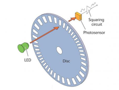
Optical sensors used in linear actuators operate using an optical encoding system consisting of three primary components: a light source (typically an infrared LED), an encoder disk with precision slots, and a photodetector positioned opposite the light source. As the actuator's drive screw rotates, it turns the encoder disk, which is mechanically coupled to the screw assembly.
The encoder disk features a pattern of alternating transparent and opaque segments arranged radially around its circumference. When the disk rotates, these slots periodically allow light from the LED to pass through and reach the photodetector on the opposite side. Each time light strikes the photodetector, it generates a voltage pulse. The photodetector circuit converts these light interruptions into clean digital pulses that can be read by a microcontroller.
The output from an optical sensor is a square wave signal where each complete cycle (high-to-low or low-to-high transition) represents a specific increment of linear travel. The resolution of the system depends on the number of slots in the encoder disk and the pitch of the actuator's lead screw. High-quality optical sensors can provide 200 to 1000+ pulses per inch of linear travel, offering exceptional positioning accuracy that far exceeds the typical 0.01-inch resolution of potentiometer-based systems.
Advantages of Optical Feedback
Optical sensors provide several significant advantages over alternative feedback methods. Unlike potentiometers, which rely on a physical wiper contact that can wear over time, optical systems have no mechanical contact in the sensing mechanism itself, resulting in longer service life and consistent performance over hundreds of thousands of cycles. The non-contact nature also eliminates issues with contact resistance, oxidation, and mechanical wear that can affect potentiometer accuracy.
Compared to hall effect sensors, optical systems typically offer 2-5 times higher resolution, enabling more precise positioning and smoother velocity control in applications like TV lifts or standing desks where subtle position adjustments matter. The optical approach is also inherently immune to magnetic interference, making it ideal for applications near motors, transformers, or other sources of electromagnetic fields that might disrupt hall effect sensors.
Understanding Incremental vs. Absolute Position
It's essential to understand that standard optical sensors provide incremental position feedback, not absolute position. The sensor counts pulses relative to a starting point but cannot inherently determine where the actuator is positioned when power is first applied. This means your control system must establish a known reference position (through a homing routine) each time the system powers up, a topic we'll cover in detail later in this guide.
Electrical Connections and Signal Output
Optical sensors integrated into feedback actuators typically use a three-wire connection scheme that provides both power to the optical components and outputs the position signal. Understanding these connections is fundamental to successful integration with your control system.
Three-Wire Connection Scheme
The three wires serve distinct functions:
- Power Supply (VCC): Provides operating voltage for the LED light source and photodetector circuit, typically 5V DC though some sensors may operate on 3.3V or 12V depending on the actuator model
- Ground (GND): Completes the electrical circuit and provides a common reference voltage
- Signal Output: Delivers the pulse train that represents actuator movement, outputting a square wave that transitions between ground (0V) and VCC level
The signal output is designed to interface directly with digital input pins on microcontrollers like Arduino boards, Raspberry Pi, or dedicated motion controllers. The signal uses TTL (Transistor-Transistor Logic) or CMOS logic levels, making it compatible with virtually all modern digital control systems without requiring additional level-shifting circuitry.
Signal Characteristics
The output signal frequency varies with actuator speed. When the actuator moves slowly, pulses occur at a lower frequency; at maximum speed, pulse frequency increases proportionally. For example, an actuator moving at 1 inch per second with a sensor providing 500 pulses per inch would generate a 500 Hz signal (500 pulses per second). Understanding this relationship helps you determine appropriate microcontroller interrupt handling capabilities and timing requirements.
The duty cycle of the square wave is typically close to 50%, meaning the signal spends equal time in the high and low states. However, your code should be designed to trigger on rising edges (or falling edges) rather than relying on specific duty cycle characteristics, as manufacturing tolerances and temperature variations can affect the exact waveform shape.
Reading Optical Sensor Feedback with a Microcontroller
Successfully reading positional feedback from an optical sensor requires careful attention to how you structure your microcontroller code. The key challenge is accurately counting rapid pulses without missing any, even while your code is performing other tasks. This is where interrupt-driven programming becomes essential.
Using External Interrupts
Microcontrollers provide special pins designated as external interrupt pins that can trigger code execution immediately when a voltage change occurs. Unlike regular polling (where your code repeatedly checks if a pin's state has changed), interrupts allow your processor to respond to each pulse within microseconds, regardless of what other code is running. This ensures you capture every pulse even when your main program loop is busy with other tasks like motor control, display updates, or communication protocols.
To utilize optical sensor feedback effectively, connect the signal output wire to an external interrupt-capable pin on your microcontroller. On Arduino boards, this typically means pins 2 and 3 (interrupt 0 and 1), though this varies by board model. Consult your specific microcontroller's documentation to identify which pins support external interrupts.
Interrupt Service Routine
Once you've configured your external interrupt, you need to define an interrupt service routine (ISR) — a special function that executes each time the interrupt is triggered. This function should be extremely short and fast, performing only the essential task of counting pulses. Lengthy operations within an ISR can cause timing problems and missed interrupts.
volatile int steps = 0;  // volatile keyword ensures variable updates are not optimized away

void setup() {
  pinMode(2, INPUT);  // Configure interrupt pin as input
  attachInterrupt(digitalPinToInterrupt(2), countSteps, RISING);  // Trigger on rising edge
}

void countSteps() {
  steps++;  // Increment pulse counter
}
The volatile keyword in the variable declaration is crucial — it tells the compiler that this variable can change at any time (via the interrupt), preventing optimization that might cache the value and cause your main code to miss updates. The RISING parameter specifies that the interrupt triggers on rising edges (low-to-high transitions), though you could use FALLING or CHANGE depending on your requirements.
Converting Pulses to Position
Counting pulses is only the first step; you need to convert that count into meaningful position information. This requires knowing the direction of travel and the previous position. Since your control code determines which direction the actuator moves (by controlling the polarity or direction signal to the motor driver), you can maintain a direction variable that your position calculation uses.
int currentPosition = 0;  // Position in pulses
int direction = 1;  // 1 for extending, -1 for retracting

void updatePosition() {
  // Temporarily disable interrupts while reading and resetting pulse count
  noInterrupts();
  int newSteps = steps;
  steps = 0;
  interrupts();

  // Update position based on direction
  currentPosition += (newSteps * direction);
}
This function safely reads the accumulated pulse count by temporarily disabling interrupts, preventing the ISR from modifying the variable while we're reading it. After copying the value and resetting the counter, interrupts are re-enabled so new pulses continue to be counted.
Converting to Physical Units
To convert from pulses to physical distance units like inches or millimeters, you need to know the pulses-per-inch specification for your specific linear actuator model. This value depends on both the encoder disk resolution and the actuator's lead screw pitch.
const float PULSES_PER_INCH = 500.0;  // Example value - check your actuator specs

float getPositionInches() {
  return currentPosition / PULSES_PER_INCH;
}
Always refer to your actuator's technical specifications for the exact pulses-per-inch value. Using an incorrect value will cause positioning errors that compound over distance, potentially leading to synchronization problems in multi-actuator systems or collisions with mechanical stops.
Homing Procedures for Known Reference Positions
Because optical sensors provide incremental rather than absolute position feedback, your control system cannot know where the actuator is positioned when power is first applied. Establishing a known reference point through a homing procedure is absolutely critical for accurate position control. Without proper homing, your position calculations will be based on an unknown starting point, making precise positioning impossible.
Basic Homing Concept
Homing involves driving the actuator to a physical limit — typically the fully retracted position — where you can definitively establish that the actuator is at a known location. This position becomes your zero reference point from which all subsequent position measurements are calculated. The fully retracted position is commonly used as home because it provides a positive mechanical stop that's easy to detect.
Implementing a Homing Routine
A robust homing routine drives the actuator toward the home position while monitoring the optical sensor output to detect when the actuator reaches the mechanical stop. When the actuator reaches full retraction, it can no longer move, so the encoder disk stops rotating and pulses cease. Your code detects this absence of pulses to determine that homing is complete.
void homeActuator() {
  steps = 0;  // Reset pulse counter
  direction = -1;  // Set to retract

  // Start retracting actuator
  digitalWrite(directionPin, LOW);  // Direction signal for retraction
  digitalWrite(motorPin, HIGH);     // Enable motor

  unsigned long lastPulseTime = millis();
  bool homed = false;

  while (!homed) {
    unsigned long currentTime = millis();

    // Check if steps variable has been updated by interrupt
    if (steps > 0) {
      steps = 0;  // Reset counter
      lastPulseTime = currentTime;  // Update timestamp
    }

    // If no pulses detected for timeout period, assume we've reached home
    if (currentTime - lastPulseTime > 200) {  // 200ms timeout
      homed = true;
    }
  }

  // Stop motor
  digitalWrite(motorPin, LOW);

  // Set current position to zero (home position)
  currentPosition = 0;
  steps = 0;
}
This routine monitors whether new pulses have been counted by checking if the steps variable has changed. It also tracks the time since the last pulse was detected. When pulses stop arriving for a specified timeout period (200 milliseconds in this example), the code assumes the actuator has reached the mechanical stop and completes the homing process.
Timeout Considerations
The timeout value requires careful tuning based on your actuator's specifications. If you set it too short, the routine might falsely detect home when the actuator is moving very slowly. Set it too long, and homing takes unnecessarily long or may continue driving against the mechanical stop, potentially causing wear. As a starting point, calculate the expected time between pulses at minimum speed, then set your timeout to 3-5 times that value to provide margin for variations.
Alternative Homing Methods
Some applications incorporate external limit switches at the fully retracted (and optionally fully extended) positions. These switches provide a definitive electrical signal when the actuator reaches the end of travel, offering more reliable homing than pulse-detection methods. When limit switches are available, your homing routine becomes simpler and more robust:
void homeActuatorWithSwitch() {
  direction = -1;  // Set to retract

  // Start retracting actuator
  digitalWrite(directionPin, LOW);
  digitalWrite(motorPin, HIGH);

  // Wait until home limit switch is activated
  while (digitalRead(homeSwitchPin) == HIGH) {
    delay(10);  // Short delay to prevent excessive polling
  }

  // Stop motor
  digitalWrite(motorPin, LOW);

  // Set current position to zero
  currentPosition = 0;
  steps = 0;
}
The use of limit switches is particularly common in industrial actuators where reliability and safety are paramount.
Handling Electrical Noise and False Triggers
While optical sensors are significantly more immune to electrical interference than potentiometers, they're not completely impervious to noise-related issues. Electrical noise from motors, switching power supplies, or other sources can couple into the signal wire and create false pulses. Even mechanical switch bouncing in relay contacts can inject transients into your power supply that manifest as spurious triggers. Left unaddressed, these false pulses accumulate as position errors that grow over time.
Software Debouncing with Timing
One effective approach to filtering false triggers is implementing a minimum time delay between accepted pulses. Since you can calculate the maximum expected pulse rate based on your actuator's maximum speed and sensor resolution, any pulse arriving faster than this maximum rate is likely noise rather than a legitimate position update.
volatile unsigned long lastInterruptTime = 0;
const unsigned long TRIGGER_DELAY = 500;  // Minimum microseconds between pulses

void countSteps() {
  unsigned long currentTime = micros();  // Get current time in microseconds

  // Only count pulse if sufficient time has passed since last pulse
  if (currentTime - lastInterruptTime > TRIGGER_DELAY) {
    steps++;
    lastInterruptTime = currentTime;
  }
}
The TRIGGER_DELAY value should be calculated based on your specific application. For an actuator with 500 pulses per inch moving at a maximum speed of 2 inches per second, the fastest legitimate pulse rate would be 1000 pulses per second, or one pulse every 1000 microseconds. Setting your trigger delay to 500 microseconds (half this value) provides a safety margin while filtering out most noise-induced false triggers.
Hardware Filtering
For applications in particularly noisy electrical environments, consider adding a small capacitor (typically 0.1μF to 1μF) between the signal wire and ground near the microcontroller input pin. This creates a low-pass filter that attenuates high-frequency noise while allowing the relatively slower optical sensor pulses to pass through. Keep the capacitor value small enough that it doesn't excessively slow the signal rise and fall times, which could cause missed pulses at high actuator speeds.
Periodic Position Correction
Even with careful noise filtering, a few false triggers may occasionally occur over thousands of cycles. A practical approach to preventing accumulated errors from affecting positioning accuracy is to periodically correct your position value when the actuator reaches a known location. This essentially performs a "soft homing" operation without requiring a full homing routine every time.
const int FULLY_RETRACTED_POSITION = 0;
const int FULLY_EXTENDED_POSITION = 5000;  // Example: 10 inches at 500 pulses/inch

void correctPosition() {
  // Check if actuator is at fully retracted position
  if (atRetractedLimit()) {
    currentPosition = FULLY_RETRACTED_POSITION;
    steps = 0;
  }

  // Check if actuator is at fully extended position
  if (atExtendedLimit()) {
    currentPosition = FULLY_EXTENDED_POSITION;
    steps = 0;
  }
}
This correction can be triggered whenever your application drives the actuator to full retraction or extension, or when external limit switches indicate an end position has been reached. By resetting the position to the known value at these points, you prevent any accumulated position errors from affecting subsequent movements.
Synchronizing Multiple Actuators with Optical Feedback
One of the most powerful applications of optical sensor feedback is synchronizing multiple linear actuators to move in perfect unison. This is critical in applications like multi-post lifts, large TV lift mechanisms, or any system where actuators must share a load evenly to prevent binding or structural stress.
Position-Based Synchronization
The high resolution of optical sensors makes them ideal for position-based synchronization algorithms. In this approach, your control system continuously monitors the position of each actuator and adjusts individual actuator speeds to maintain alignment. When one actuator falls behind, its speed is increased slightly; when it gets ahead, its speed is reduced.
This type of sophisticated control requires either a capable microcontroller running custom code or a dedicated controller like FIRGELLI's FA-SYNC-X, which is specifically designed to maintain synchronized motion across multiple actuators even when they experience different loads. The FA-SYNC-X continuously monitors position feedback from each actuator and automatically adjusts PWM duty cycle to individual actuators to maintain synchronization within a few pulses.
Synchronized Motion Benefits
Proper synchronization prevents mechanical binding in systems where actuators share a common load platform. Without synchronization, one actuator might extend slightly faster than its paired unit, causing the platform to tilt. This tilt increases side loading on both actuators, accelerating wear and potentially causing premature failure. The precise feedback from optical sensors allows your control system to detect position mismatches of just a few thousandths of an inch and correct them before mechanical stress becomes significant.
Practical Implementation Considerations
Wire Routing and Shielding
Pay attention to how you route the sensor wires from the actuator to your controller. Keep sensor wires separate from high-current motor power wires to minimize electromagnetic interference. If running wires in the same cable bundle is unavoidable, consider using twisted-pair wiring for the sensor connections, which helps cancel induced noise through common-mode rejection.
Power Supply Quality
The optical sensor requires clean, stable DC power to operate reliably. If you're powering both the actuator motors and the sensor electronics from the same power supply, ensure the supply has adequate current capacity and good voltage regulation. Motor starting currents can cause voltage sags that might disrupt sensor operation or cause the microcontroller to reset. Using separate regulated supplies for control electronics and motor power is often worthwhile in precision applications.
Environmental Considerations
While optical sensors are sealed within the actuator housing, extreme environmental conditions can still affect performance. Very high temperatures may cause expansion of mechanical components that slightly affects calibration. Excessive vibration or shock loads can potentially disturb the encoder disk alignment. If your application involves harsh environments, consider industrial actuators with enhanced environmental ratings.
Maintenance and Longevity
One significant advantage of optical sensors is their maintenance-free operation. Unlike potentiometers with wipers that eventually wear, optical systems have no contacting components in the encoder itself. The LED light source does have a finite lifetime (typically 100,000+ hours), but this translates to many years of operation in most applications. Over the actuator's service life, the mechanical components (lead screw, nut, bushings) will typically wear long before the optical sensor fails.
Troubleshooting Common Issues
No Pulse Output
If your microcontroller isn't receiving any pulses when the actuator moves, first verify voltage at the sensor power pins using a multimeter. Confirm that you have the correct voltage (typically 5V DC) and that power and ground are connected to the correct wires. If power is present, check that your signal wire is connected to a functioning microcontroller input pin and that the pin is properly configured in your code.
Erratic Pulse Counts
Inconsistent pulse counts that don't correspond to actuator movement suggest electrical noise issues. Verify that you've implemented proper debouncing in your interrupt service routine and that the sensor ground shares a common reference with your microcontroller ground. Adding a small capacitor for hardware filtering can help stabilize noisy signals.
Position Drift Over Time
If your calculated position gradually drifts away from the actual actuator position over many cycles, you likely have occasional missed or false pulses. Examine your interrupt service routine to ensure it's fast and efficient. Consider implementing periodic position correction at known reference points to prevent drift from accumulating. Verify that your microcontroller isn't being overwhelmed by other tasks that might delay interrupt processing.
Homing Failures
If homing routines fail to complete or establish incorrect home positions, check your timeout values. Too short a timeout causes premature homing completion; too long delays the routine unnecessarily. Verify that your pulse-detection logic correctly identifies when pulses stop arriving. If using limit switches for homing, confirm the switches are functioning properly and that pull-up or pull-down resistors are correctly configured.
Conclusion
Optical sensor feedback represents a sophisticated yet accessible approach to precision position control in linear actuator systems. By understanding the fundamental operation of optical encoders, implementing proper interrupt-driven pulse counting, establishing reliable homing procedures, and addressing potential noise issues, you can build motion control systems with exceptional accuracy and reliability. The high resolution offered by optical sensors — often 200 to 1000+ pulses per inch — enables positioning precision measured in thousandths of an inch, making them ideal for applications ranging from synchronized multi-actuator systems to precision automation equipment.
While optical feedback requires more sophisticated programming than simple limit-switch control, the investment in proper implementation pays dividends through improved positioning accuracy, repeatable motion profiles, and the ability to synchronize multiple actuators even under varying loads. Whether you're building custom automation with an Arduino microcontroller or integrating with professional control systems, optical sensor feedback provides the precise position data your application needs for truly professional results.
Frequently Asked Questions
What is the difference between optical and hall effect sensors for linear actuators?
Optical sensors detect position changes by monitoring light passing through slots in an encoder disk, while hall effect sensors detect changes in magnetic field as magnets pass by the sensor. Optical sensors typically provide 2-5 times higher resolution than hall effect sensors, making them better for applications requiring precise positioning. Optical sensors are also immune to magnetic interference, which can be important in environments with strong electromagnetic fields from motors or other equipment. However, both sensor types provide incremental feedback requiring homing procedures, and both output similar square-wave pulse signals that can be processed identically by your microcontroller code.
How many pulses per inch should I expect from an optical sensor?
The pulses-per-inch value varies depending on the specific feedback actuator model and is determined by both the encoder disk resolution and the actuator's lead screw pitch. Typical values range from 200 to 1000+ pulses per inch. Higher pulse counts provide finer position resolution but also generate faster pulse rates at high actuator speeds, which requires more capable interrupt processing in your microcontroller. Always consult your specific actuator's technical specifications for the exact pulses-per-inch value, as using an incorrect value in your code will cause positioning errors.
Do I need to home my actuator every time the system powers on?
Yes, because optical sensors provide incremental position feedback rather than absolute position, you must perform a homing routine each time power is applied to establish a known reference position. Without homing, your microcontroller has no way to determine where the actuator is positioned. The homing process typically takes just a few seconds and is essential for accurate position control. Some applications minimize this inconvenience by keeping actuators at a known position when shutting down, reducing the time required for the next startup homing routine.
Can optical sensor feedback work with Arduino microcontrollers?
Yes, optical sensors work excellently with Arduino and similar microcontrollers. The 5V TTL-compatible output from most optical sensors interfaces directly with Arduino digital input pins without requiring level shifters or special circuitry. Arduino's external interrupt functionality (available on pins 2 and 3 on Uno/Nano boards) is specifically designed for counting rapid pulses like those from optical sensors. The main requirement is writing efficient interrupt service routines and ensuring your main loop doesn't consume so much processing time that it interferes with interrupt handling.
How do I synchronize multiple actuators using optical feedback?
Synchronizing multiple actuators requires continuously monitoring the position feedback from each unit and adjusting individual actuator speeds to maintain alignment. This can be accomplished with custom microcontroller code that compares positions and adjusts PWM signals to individual linear actuators, or through specialized controllers like FIRGELLI's FA-SYNC-X that automatically handle synchronization. The high resolution of optical sensors makes them particularly well-suited for synchronization because they can detect position differences of just a few thousandths of an inch, allowing the control system to make corrections before misalignment becomes mechanically significant.
What causes position drift and how can I prevent it?
Position drift occurs when your calculated position gradually diverges from the actuator's actual position due to missed pulses (interrupts not processed in time) or false triggers (electrical noise counted as legitimate pulses). Prevent drift by ensuring your interrupt service routine executes quickly, implementing software debouncing to filter noise-induced false triggers, using hardware filtering (small capacitor on signal line), and periodically correcting position when the actuator reaches known reference points. Even with these measures, some applications benefit from re-homing periodically during operation to reset any accumulated errors.
Can I use optical feedback actuators in outdoor or harsh environments?
While the optical sensor itself is sealed within the actuator housing, extreme environmental conditions can affect performance. Temperature extremes may cause component expansion affecting calibration precision, and severe vibration or shock loading could potentially disturb the encoder disk alignment. For outdoor or industrial applications with harsh conditions, consider industrial actuators with enhanced environmental ratings, including improved sealing and temperature-compensated designs. The optical sensing mechanism is generally more robust than potentiometers in dirty environments since it doesn't rely on sliding electrical contacts that can be affected by dust or contamination.


