Understanding position feedback is critical when designing automated motion control systems. Whether you're building a standing desk, automated window opener, or precision testing equipment, knowing exactly where your linear actuator is positioned allows you to create intelligent, self-correcting systems that respond to real-world conditions. Among the various feedback technologies available, potentiometer-based feedback offers an accessible, cost-effective solution for many applications.
Potentiometers provide analog position feedback by varying resistance as the actuator extends and retracts. This simple yet effective technology has been used in industrial automation for decades, and when properly implemented with a microcontroller like an Arduino, it enables precise position control without the complexity of digital encoders or optical sensors. However, working with potentiometer feedback requires understanding both the hardware connections and the software techniques needed to interpret the analog signal reliably.
This comprehensive guide will walk you through everything you need to know about implementing potentiometer feedback in your linear actuator projects, from basic wiring and signal interpretation to advanced filtering techniques and multi-actuator synchronization challenges.
In feedback systems, wiring and grounding decide accuracy as much as the sensor does. A clean signal path with separated power and signal wires usually outperforms a "better" sensor wired poorly.
"Potentiometer feedback gets blamed for problems it didn't cause. Most jittery readings aren't the pot — they're motor noise coupling into a signal wire that was run alongside the power leads. Separate the wiring, add a 0.1 µF cap, average five to ten samples, and the same actuator suddenly looks precise." — Robbie Dickson, Founder and Chief Engineer of FIRGELLI Automations
How does potentiometer feedback work in a linear actuator?
A potentiometer is essentially a variable resistor with three terminals. In feedback actuators, the potentiometer is mechanically coupled to the actuator's drive mechanism, typically through a gear train that converts the linear motion into rotary motion. As the actuator extends or retracts, the potentiometer's wiper moves along a resistive element, changing the resistance between the terminals.
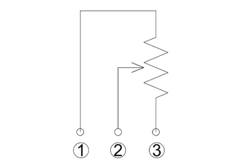
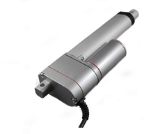
Linear actuators equipped with potentiometer feedback include three additional wires beyond the standard motor power wires:
- Wire 1 (Input Voltage): Supplies reference voltage to the potentiometer, typically the same voltage as your microcontroller (5V for most Arduino boards, 3.3V for some others)
- Wire 2 (Signal Output): The variable voltage output that changes proportionally with actuator position
- Wire 3 (Ground): Common ground reference shared with your control circuit
The key principle is straightforward: as the actuator moves, the voltage on Wire 2 changes proportionally between ground (0V) and the input voltage. By measuring this voltage, you can determine the absolute position of the actuator at any moment. This differs from incremental encoders that only track movement direction and distance, making potentiometers ideal for applications where you need to know exact position even after power loss or system reset.
How do you wire potentiometer feedback to a microcontroller?
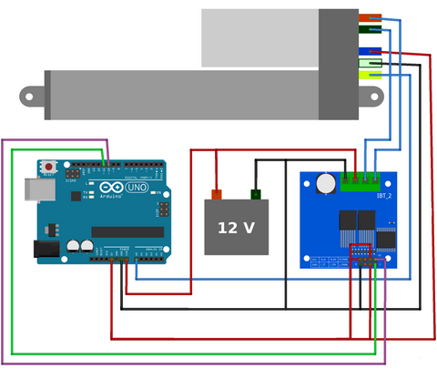
Connecting potentiometer feedback to an Arduino or similar microcontroller requires careful attention to voltage compatibility and proper grounding. The analog input pins on most microcontrollers feature built-in Analog-to-Digital Converters (ADCs) that translate the continuous voltage signal into discrete digital values your code can process.
Understanding ADC Resolution
The Arduino Uno and most AVR-based boards use 10-bit ADCs, which convert the analog voltage into values ranging from 0 to 1023. This means a 5V input range is divided into 1024 distinct steps, giving you approximately 4.88mV resolution per step (5V ÷ 1024). For a 12-inch stroke linear actuator, this translates to roughly 0.012 inches of theoretical position resolution.
Other microcontroller platforms offer different resolutions. The table below compares common ADC bit depths and what they mean for a 12-inch stroke actuator at a 5V reference (theoretical resolution, before noise and backlash are accounted for):
| ADC Bit Depth | Value Range | Steps | Resolution at 5V | Resolution on 12" stroke (theoretical) |
|---|---|---|---|---|
| 8-bit | 0–255 | 256 | 19.5 mV | 0.047" |
| 10-bit (Arduino Uno) | 0–1023 | 1024 | 4.88 mV | 0.012" |
| 12-bit (ARM Cortex-M) | 0–4095 | 4096 | 1.22 mV | 0.003" |
| 16-bit | 0–65535 | 65536 | 0.076 mV | <0.001" |
Higher ADC resolution provides more granular position data, but practical limitations like electrical noise and mechanical backlash in the actuator's gearbox often become the limiting factors before ADC resolution matters.
Connection Best Practices
When wiring your potentiometer feedback:
- Keep the feedback signal wires away from motor power wires to minimize electromagnetic interference
- Use twisted pair or shielded cable for the signal wire in electrically noisy environments
- Ensure a solid common ground between the actuator, microcontroller, and power supply
- Never exceed the microcontroller's maximum input voltage on the analog pin (typically 5V or 3.3V)
- Consider adding a small capacitor (0.1µF) between the signal wire and ground at the microcontroller to filter high-frequency noise
How do you read and interpret the position data?
Once wired correctly, reading potentiometer feedback in Arduino is accomplished using the analogRead() function. However, converting the raw ADC value into meaningful position data requires calibration specific to your actuator.
Calibrating Your Actuator
The internal gearbox and mechanical limits of your linear actuator prevent the potentiometer from rotating through its full range. This means your ADC values won't span the complete 0-1023 range. Calibration involves determining the actual minimum and maximum ADC values at the fully retracted and fully extended positions.
For example, a 4-inch stroke feedback rod actuator might output:
- ADC value of 44 at fully retracted (0 inches)
- ADC value of 951 at fully extended (4 inches)
With these calibration points, you can calculate position using a linear interpolation formula:
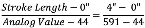
This relationship can be simplified algebraically. For the example above, the formula becomes:
Stroke Length = 0.00441 × (Analog Value - 44)
Where 0.00441 is derived from: 4 inches ÷ (951 - 44) = 4 ÷ 907 ≈ 0.00441
Reading Frequency Considerations
How often you sample the potentiometer affects both system responsiveness and processor load. Several strategies exist:
- Event-driven reading: Read position only while the actuator is moving, reducing unnecessary processing
- Timer-based reading: Use hardware timers to sample at fixed intervals (e.g., every 100ms), ensuring consistent update rates
- Continuous reading: Place analogRead() in the main loop for constant updates, suitable for simple applications but can monopolize processor time in complex projects
For most applications involving feedback actuators, event-driven or timer-based approaches offer the best balance between responsiveness and efficiency. Reading position 10-20 times per second typically provides smooth control without overwhelming the microcontroller.
How do you deal with electrical noise and signal instability?
Electrical noise is the primary challenge when working with potentiometer feedback. DC motors generate significant electromagnetic interference (EMI) during operation, and this noise couples into the analog signal wires, causing position readings to fluctuate unpredictably. In applications with multiple motors, inductive loads, or switching power supplies, noise can make raw position data virtually unusable.
Implementing a Running Average Filter
The most practical software solution for linear actuator applications is a running average filter (also called a moving average). This digital filter smooths the input signal by averaging the last N measurements, effectively removing high-frequency noise while preserving the actual position trend.
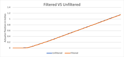
The graph above demonstrates the effectiveness of a running average filter. The blue line shows the noisy raw input signal, while the red line displays the smoothed output after filtering. Notice how the filtered signal tracks the general trend while eliminating the rapid fluctuations.
Choosing the optimal number of samples to average requires balancing two competing factors:
- Too few samples (N=2-3): Insufficient noise reduction, signal remains jittery
- Too many samples (N=20+): Excessive lag, the filtered position trails significantly behind actual position
- Optimal range (N=5-10): Adequate smoothing with acceptable lag for most applications
The ideal value depends on your specific noise environment and application requirements. Start with 5 samples and adjust based on observed performance. Applications requiring rapid response (like active suspension systems) need fewer samples, while slower-moving applications (like TV lifts or standing desks) can use more aggressive filtering.
Advanced Filtering Techniques
For particularly challenging noise environments, consider these additional strategies:
Exponential Moving Average (EMA): Weights recent measurements more heavily than older ones, providing better responsiveness than simple averaging while still filtering noise. The formula is: Filtered Value = (α × New Reading) + ((1-α) × Previous Filtered Value), where α is a smoothing factor between 0 and 1.
Median Filter: Instead of averaging, takes the middle value from the last N samples. Particularly effective at removing occasional large spikes or outliers, though computationally more expensive than averaging.
Kalman Filter: Advanced predictive filter that estimates actuator position based on both measurements and a motion model. Overkill for most hobbyist projects but valuable in precision industrial applications.
Hardware-Based Noise Reduction
Software filtering works best when combined with proper hardware design:
- Add a 0.1µF ceramic capacitor between the signal wire and ground at the microcontroller input
- Use ferrite beads on motor power wires to suppress EMI
- Implement physical separation between high-current motor wires and low-voltage signal wires
- Use shielded cable for signal wires in electromagnetically noisy environments, grounding the shield at one end only
- Ensure stable, well-regulated input voltage to the potentiometer, as voltage fluctuations directly affect the output signal
How do you implement automated position control?
The real power of potentiometer feedback lies in creating self-correcting automated systems. By continuously comparing desired position to actual position, you can implement closed-loop control that automatically drives the actuator to target positions with minimal user intervention.
Basic Position Control Algorithm
The fundamental approach is straightforward:
- Read current position from potentiometer
- Compare to desired target position
- If current position is less than target, extend the actuator
- If current position is greater than target, retract the actuator
- Stop when within acceptable tolerance of target
This simple bang-bang control works well for many applications, though it causes the actuator to hunt (oscillate slightly) around the target position. The tolerance window determines how close the actuator must get before stopping—too tight and the system hunts continuously, too loose and positioning accuracy suffers.
Accuracy and Repeatability Limitations
Potentiometer feedback has inherent limitations affecting precision:
Resolution Constraints: The combination of ADC resolution and potentiometer linearity typically limits practical position resolution to 1-2% of total stroke length. A 10-inch actuator might achieve ±0.1 inch repeatability under ideal conditions.
Mechanical Backlash: Gearbox backlash means the actuator can move slightly without the potentiometer changing position, introducing hysteresis into position measurements. Approaching a position from different directions may yield slightly different readings.
Temperature Sensitivity: Potentiometer resistance and motor characteristics both vary with temperature, affecting calibration accuracy over wide temperature ranges.
Wear and Drift: Potentiometers experience mechanical wear over millions of cycles, gradually degrading accuracy. Regular recalibration may be necessary in high-cycle applications.
For applications requiring positioning precision better than 1-2% of stroke length, consider feedback actuators with optical encoders or hall-effect sensors, or supplement potentiometer feedback with external limit switches or proximity sensors at critical positions.
What goes wrong when synchronizing multiple actuators with potentiometer feedback?
Controlling multiple linear actuators simultaneously introduces additional complexity. Applications like adjustable standing desks, four-corner vehicle leveling systems, or coordinated hatch mechanisms require multiple actuators to move in precise synchronization.
Synchronization Difficulties with Potentiometer Feedback
Several factors complicate multi-actuator control:
Manufacturing Tolerances: Even identical actuator models have slight variations in internal gearing, motor characteristics, and potentiometer calibration. Two actuators commanded to the same position will reach slightly different actual positions.
Load Variations: Actuators supporting different loads will move at different speeds and exhibit different electrical characteristics, making synchronized movement challenging.
Crosstalk and Interference: Multiple motors generate more electrical noise, affecting all potentiometer readings. Signal wires can pick up interference from nearby actuators, causing correlated noise that's difficult to filter.
Voltage Sag: Running multiple high-current actuators simultaneously can cause power supply voltage to sag, affecting both motor speed and potentiometer reference voltage. This makes position readings inconsistent between actuators.
Strategies for Improved Synchronization
To achieve better multi-actuator coordination with potentiometer feedback:
Individual Calibration: Calibrate each actuator separately and store unique calibration constants. Never assume identical actuators will have identical potentiometer ranges.
Position-Based Speed Control: Slow down actuators that are ahead of the group average, allowing lagging actuators to catch up. This requires PWM motor control rather than simple on/off switching.
Staged Operation: For applications where perfect synchronization isn't critical, sequence actuator movements rather than running all simultaneously. This reduces total current draw and electromagnetic interference.
Robust Power Design: Use appropriately sized power supplies with sufficient current capacity and low output impedance to prevent voltage sag during simultaneous operation.
Physical Wire Routing: Route potentiometer signal wires away from motor power wires. Use separate wire harnesses or maintain physical separation to minimize electromagnetic coupling.
Consider Alternative Feedback: For applications demanding tight synchronization (±0.5% stroke length), optical encoders or hall-effect sensors provide superior accuracy and noise immunity compared to potentiometers. While more expensive, the improved performance may justify the cost in demanding applications.
Where is potentiometer feedback used in practice?
Understanding potentiometer feedback implementation becomes clearer through real-world examples:
Adjustable Standing Desk
A motorized standing desk uses potentiometer feedback to remember preset heights (sitting, standing, presentation mode). The system doesn't require extreme precision—being within ±0.25 inches of target height is perfectly acceptable. A running average filter with N=7 samples provides stable readings despite motor noise. The user presses a button, and the desk automatically drives to the stored position without manual adjustment.
Automated Window Opener
An automated skylight uses a micro linear actuator with potentiometer feedback integrated with rain and temperature sensors. When temperature exceeds a threshold, the window opens to a preset position for ventilation. If rain is detected, it immediately closes regardless of temperature. The potentiometer allows the system to open partially (25%, 50%, 75%) rather than just fully open or closed, providing proportional ventilation control.
Camera Slider
A motorized camera slide rail with potentiometer feedback enables programmable time-lapse photography. The system moves the camera smoothly between defined start and end positions over several hours, with the potentiometer ensuring consistent, repeatable motion paths. Exponential filtering (α=0.3) provides smooth motion without the lag that would occur with simple averaging.
What does the Arduino code look like?
Below are practical Arduino code examples demonstrating potentiometer feedback implementation. These examples assume a 4-inch stroke feedback actuator calibrated with minimum ADC value of 44 at 0 inches and maximum value of 951 at 4 inches.
Basic Position Reading
This code reads the potentiometer while the actuator is moving and converts the ADC value to stroke length in inches:
Running Average Filter Implementation
This enhanced version implements a 3-sample running average filter to smooth the position reading:
The array positionArray[] stores the last three measurements, and the code calculates their average to produce a filtered position value. For noisier environments, increase the array size to 5 or 7 samples and adjust the averaging calculation accordingly.
What usually goes wrong with potentiometer feedback?
Most failures with potentiometer feedback are wiring or assumption problems, not sensor problems. The recurring offenders we see on the FIRGELLI bench:
- Signal wire run alongside motor power wires. The pot picks up EMI from the motor leads, and position readings jump unpredictably whenever the motor draws current.
- No common ground between actuator, microcontroller, and power supply. Readings drift or float because the ADC has no stable reference relative to the pot's ground.
- Calibration assumes the full 0–1023 ADC span. Real actuators rarely use the entire pot range — you must measure end-stop ADC values for each unit.
- Bang-bang control with no tolerance window. The actuator hunts and oscillates around the target instead of settling.
- Voltage sag from an undersized power supply. When multiple actuators run together, the pot reference voltage drops, and position readings shift even though nothing physically moved.
- Mechanical backlash ignored in the algorithm. Approaching the same target from extend vs. retract gives different readings, and the control loop treats that as a real position error.
- Pot wear after high cycle counts. Gradual drift appears; recalibration becomes necessary in high-cycle applications.
How should you test potentiometer feedback before trusting it?
Calibration alone is not validation. Before relying on potentiometer feedback in a finished system, put it through these tests:
- Cycle-and-record. Record raw ADC values at full retract and full extend, then repeat after 10 full cycles. Drift between the two runs reveals mechanical slop or pot wear.
- Approach-from-both-directions. Drive to the same target from extend-then-stop and retract-then-stop. The ADC delta between the two approaches is your backlash budget — and your control loop must tolerate it.
- Loaded test. Run the actuator under its expected load, not just unloaded on the bench. Loaded motor current pulls more from the supply and changes the noise floor on the signal wire.
- Log raw vs. filtered. While the motor is running, log both raw and filtered values. If the filtered line still wanders more than a few ADC counts at rest, your wiring layout — not your filter — is the problem.
- Multi-actuator stress test. For multi-actuator setups, run all actuators simultaneously and verify the reference voltage at each pot stays stable. Sag at the pot supply is invisible from a single-actuator bench test.
When should you use potentiometer feedback?
Potentiometer feedback represents an excellent entry point into closed-loop actuator control. It provides absolute position information with simple wiring and straightforward software implementation. For projects where positioning accuracy of 1-2% of stroke length is acceptable, where environmental noise is manageable, and where cost-effectiveness is important, potentiometer feedback delivers reliable performance.
However, recognize its limitations. Applications requiring sub-millimeter repeatability, harsh electromagnetic environments with multiple motors, or tight multi-actuator synchronization may benefit from more sophisticated feedback technologies. Hall-effect sensors and optical encoders offer superior noise immunity and resolution at higher cost and complexity.
The key is matching feedback technology to application requirements. Many successful automation projects—from TV lifts to adjustable workbenches to automated hatches—rely on potentiometer feedback because it provides sufficient accuracy at reasonable cost. By implementing proper filtering techniques, following good wiring practices, and understanding the system's capabilities and constraints, you can create robust, reliable motion control systems with potentiometer feedback.
Industries and applications covered: smart furniture and home office (standing desks, TV lifts), home automation (automated window and skylight openers), entertainment and content creation (camera sliders, time-lapse rigs), and light industrial automation (multi-actuator synchronization, hatch mechanisms, leveling systems).
Frequently Asked Questions
What voltage should I supply to the potentiometer feedback wire?
Supply the same voltage as your microcontroller's logic level—5V for most Arduino boards (Uno, Mega, Nano) or 3.3V for ARM-based boards and newer Arduino models (Due, Zero, MKR series). Never exceed your microcontroller's maximum input voltage on analog pins, as this can permanently damage the ADC circuitry. The potentiometer acts as a voltage divider, so the input voltage directly affects the output signal range. Using a stable, regulated voltage source improves measurement accuracy and consistency.
How do I calibrate a linear actuator with potentiometer feedback?
Calibration is a two-step process: First, upload a simple sketch that continuously reads and displays the analog value from your potentiometer. Second, manually drive the actuator to its fully retracted position and record the ADC value, then drive it fully extended and record that value. These two calibration points define the minimum and maximum of your position range. Use the formula: Position = (Stroke Length) × (Current ADC Value - Min ADC Value) ÷ (Max ADC Value - Min ADC Value). Store these calibration values in your code or in EEPROM for permanent reference. Recalibrate if you notice position drift over time or after mechanical adjustments to the actuator.
Why is my position reading jumping around or unstable?
Unstable readings typically result from electrical noise generated by the DC motor coupling into the analog signal wire. Motors create significant electromagnetic interference, especially during direction changes or under heavy load. Solutions include implementing a software running average filter (start with 5-7 samples), adding a small capacitor (0.1µF) between the signal wire and ground at the microcontroller, physically separating signal wires from motor power wires, using twisted pair or shielded cable for signal wires, and ensuring all grounds are properly connected. Also verify your power supply provides stable voltage without excessive ripple, as voltage fluctuations affect both motor operation and potentiometer readings.
Why won't my actuator stop at the exact target position?
Several factors prevent precise positioning with potentiometer feedback: mechanical backlash in the gearbox means the actuator must move slightly before the potentiometer responds; motor inertia causes the actuator to overshoot before stopping; ADC resolution limits how finely you can detect position changes; and control algorithms using bang-bang (on/off) control cause hunting around the target. Improve accuracy by implementing a tolerance window (stop when within ±2-3 ADC counts of target), using PWM to slow the actuator as it approaches the target, approaching the target from the same direction consistently to eliminate backlash effects, and accepting that potentiometer feedback typically achieves ±1-2% stroke length repeatability rather than absolute precision.
Can I synchronize multiple linear actuators using potentiometer feedback?
Yes, but with limitations. Manufacturing tolerances mean identical actuators won't have identical potentiometer ranges or motor speeds, so individual calibration is essential. Implement position-based speed control where you slow down actuators that are ahead of the group, allowing lagging units to catch up. Use separate analog input pins for each actuator's potentiometer and ensure adequate power supply capacity to prevent voltage sag affecting readings. Route signal wires away from motor power wires to minimize crosstalk. For applications requiring tight synchronization (better than ±2% stroke length), consider feedback actuators with optical encoders instead, as they provide superior noise immunity and resolution compared to potentiometers.
What's the difference between potentiometer, hall-effect, and optical encoder feedback?
Potentiometer feedback uses a variable resistor providing analog voltage output proportional to position. It's cost-effective and provides absolute position (knows position even after power loss) but is susceptible to electrical noise and has limited resolution. Hall-effect sensors use magnetic fields to detect position, offering better noise immunity than potentiometers with similar cost, but typically provide incremental rather than absolute position. Optical encoders use light interruption to count position changes, providing the highest resolution and excellent noise immunity, but are more expensive and provide incremental rather than absolute position (must home to a reference point after power-up). For most hobbyist projects and general automation, potentiometer feedback offers the best balance of cost, simplicity, and performance. Choose hall-effect or optical encoders when working in electrically noisy environments or requiring precision better than 1% of stroke length.


