When implementing linear actuators in automation systems, the difference between basic open-loop control and precision closed-loop operation comes down to one critical factor: feedback. Whether you're engineering a robotic assembly line, designing a medical device, or building a custom TV lift, understanding the feedback mechanism in your actuator directly impacts positioning accuracy, repeatability, and overall system reliability.
Feedback systems transform linear actuators from simple electric motors into intelligent positioning devices. Without feedback, you're essentially running blind—applying voltage and hoping your actuator reaches the desired position. With proper feedback implementation, you gain real-time position data that enables precise control, synchronized multi-actuator systems, and the ability to compensate for varying loads and environmental conditions. This capability is particularly crucial in applications requiring sub-millimeter accuracy or coordinated motion across multiple axes.
This comprehensive guide examines the three primary feedback technologies used in modern feedback actuators: potentiometric sensors, Hall effect sensors, and optical encoders. Each technology offers distinct advantages and trade-offs in terms of resolution, absolute versus incremental positioning, cost, and implementation complexity. Understanding these differences will help you select the right feedback solution for your specific application requirements.
Why Feedback Matters in Linear Actuator Systems
Before diving into specific feedback technologies, it's important to understand why feedback is essential for modern motion control applications. Open-loop control—simply applying voltage to move an actuator without position verification—may work for basic applications, but it introduces several limitations that become critical in professional implementations.
Without feedback, you cannot account for load variations. An actuator pushing against a heavy load will move more slowly and may not reach the target position within the expected time frame. Environmental factors like temperature changes affect motor performance and gear efficiency, causing position drift over time. Mechanical wear in the gearbox and lead screw gradually changes the actuator's stroke characteristics, making manual calibration increasingly unreliable.
Feedback systems solve these problems by providing continuous position data that enables closed-loop control. Your controller can compare the actual position against the target position and make real-time adjustments to ensure accurate positioning regardless of external variables. This capability is non-negotiable in applications like medical equipment, industrial actuators in manufacturing, and any system where safety or precision is paramount.
Potentiometric Feedback: Absolute Position Sensing
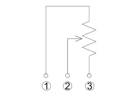
Potentiometric feedback represents the most straightforward approach to position sensing in linear actuators. A potentiometer is essentially a variable resistor mechanically linked to the actuator's drive mechanism. As the actuator extends or retracts, the potentiometer's wiper moves along a resistive element, producing a voltage output that corresponds directly to the actuator's position.
How Potentiometric Feedback Works
The potentiometer configuration used in linear actuators consists of three pins: an input voltage pin (typically 5V or 12V DC), a ground pin, and an output signal pin. The input voltage is applied across the entire resistive element, while the output pin connects to the wiper that moves with the actuator. As the actuator position changes, the resistance between the output pin and ground changes proportionally, creating a variable voltage signal.
Reading this signal requires a controller capable of analog-to-digital conversion, such as an Arduino or similar microcontroller. The controller measures the voltage on the output pin and converts it to a position value. For example, if your potentiometer is supplied with 5V and your actuator has a 10-inch stroke, you might measure 0.5V when fully retracted (0 inches), 2.75V at mid-stroke (5 inches), and 5V when fully extended (10 inches).
Advantages of Potentiometric Feedback
The primary advantage of potentiometric feedback is that it provides absolute position information. Unlike incremental feedback systems that count pulses, a potentiometer always indicates exactly where the actuator is positioned, regardless of whether the system has just powered on or has been running for hours. This eliminates the need for homing sequences at startup—a significant advantage in applications where the actuator must maintain its position during power interruptions.
Implementation is relatively simple from a software perspective. You don't need complex pulse counting algorithms or position tracking variables. Simply read the analog voltage, convert it to a position value using a linear equation, and compare it to your target position. This makes potentiometric feedback ideal for simpler control systems or applications where processing power is limited.
Another practical benefit is that potentiometers are robust mechanical devices with no complex electronics. They're less sensitive to electromagnetic interference than digital sensors and can operate reliably in harsh industrial environments where electrical noise might be a concern.
Limitations of Potentiometric Feedback
Despite these advantages, potentiometric feedback has several limitations that make it less suitable for high-precision applications. The resolution is inherently limited by the quality of the potentiometer and the bit depth of your analog-to-digital converter. A typical 10-bit ADC reading a potentiometer provides only 1024 discrete position values across the entire stroke length. For a 10-inch actuator, this translates to roughly 0.01-inch resolution—adequate for many applications but insufficient for precision positioning requirements.
Electrical noise can significantly affect potentiometric readings. The analog signal is susceptible to interference from motor noise, nearby electrical equipment, and even long wire runs between the actuator and controller. While filtering techniques can mitigate this issue, they add latency and complexity to your control system. Multiple actuators controlled from the same power supply may exhibit slight variations in their potentiometer output due to voltage ripple or drops, making perfect synchronization challenging.
The potentiometer itself is also a wear item. The wiper makes physical contact with the resistive element, and over millions of cycles, this contact can degrade, leading to noise, dead spots, or eventual failure. While quality potentiometers are rated for hundreds of thousands of cycles, this is a consideration in high-duty-cycle applications.

Hall Effect Sensor Feedback: Precision Through Magnetic Pulses
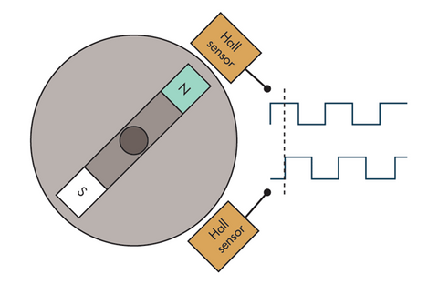
Hall effect sensors represent a significant step up in resolution and reliability compared to potentiometric feedback. These sensors exploit the Hall effect—a phenomenon where a magnetic field induces a voltage across a conductor—to detect the rotation of a magnetic disc inside the actuator's gearbox. This technology provides incremental feedback through a series of digital pulses, with each pulse representing a precise increment of movement.
Hall Effect Sensor Operating Principle
Inside a linear actuator equipped with Hall effect feedback, one or more Hall effect sensors are positioned adjacent to a multi-pole magnetic disc attached to the gear train. As the actuator moves and the gearbox rotates, the magnetic poles pass by the sensor, alternating between north and south magnetic fields. Each transition triggers the Hall effect sensor to output a voltage pulse.
The number of pulses per inch of travel varies by actuator design but typically ranges from several hundred to over 12,000 pulses per inch in high-resolution models. This specification is crucial for determining positioning accuracy. For example, a feedback actuator with 12,000 pulses per inch provides a theoretical resolution of approximately 0.00008 inches (2 microns) per pulse—far exceeding what's achievable with potentiometric feedback.
Implementing Hall Effect Feedback
Implementing Hall effect feedback requires a controller capable of reading high-frequency digital pulses and maintaining an accurate count. Modern microcontrollers like those used in Arduino platforms handle this easily through interrupt-driven pulse counting. Your software must increment or decrement a position counter with each pulse, depending on the direction of movement.
The calculation is straightforward: if you've counted 6,000 pulses and your actuator has a specification of 12,000 pulses per inch, dividing 6,000 by 12,000 tells you the actuator has moved 0.5 inches. To determine absolute position, you need to know the starting point, which typically requires a homing sequence where the actuator retracts fully to a known reference position at startup.
Many Hall effect sensors output two channels (A and B) in quadrature—90 degrees out of phase. This quadrature output serves two purposes: it doubles the effective resolution by counting both rising and falling edges of both channels, and it allows the controller to determine the direction of movement by examining which channel leads the other.
Advantages of Hall Effect Feedback
The resolution advantage of Hall effect feedback cannot be overstated. With thousands of pulses per inch, these sensors enable positioning accuracy measured in hundredths or even thousandths of an inch. This precision is essential in applications like medical devices, precision manufacturing equipment, and robotic systems where repeatability is critical.
Hall effect sensors also provide velocity information inherently. By measuring the frequency of incoming pulses, your controller can determine the actuator's speed in real-time. This enables sophisticated control algorithms that can adjust motor voltage to maintain constant speed regardless of load, or implement smooth acceleration and deceleration profiles.
For multi-actuator synchronization, Hall effect feedback is far superior to potentiometric feedback. The digital pulse counting is not affected by voltage variations or analog signal noise, making it possible to keep multiple actuators perfectly synchronized even under varying loads. FIRGELLI's FA-SYNC-X controller specifically leverages this capability to maintain synchronization across multiple axes with impressive precision.
Hall effect sensors are also non-contact devices with no mechanical wear components, providing superior longevity compared to potentiometers. They're immune to vibration and can handle the harsh mechanical environment inside an actuator gearbox without degradation.
Limitations of Hall Effect Feedback
The primary limitation of Hall effect feedback is that it provides incremental rather than absolute position information. The controller must count every pulse from a known starting point, which means any missed pulses due to electrical noise, signal processing errors, or power interruptions result in position error that accumulates over time.
This characteristic necessitates a homing routine at system startup. The actuator must move to a known reference position—typically fully retracted to a mechanical stop—and reset the pulse counter to zero. This homing process adds complexity to system initialization and may be problematic in applications where the actuator needs to remain in position during power cycles.
The controller must continuously track position in non-volatile memory if position must be maintained across power cycles. This requires additional programming complexity and may introduce reliability concerns if the memory write operations occur frequently.
Optical Encoder Feedback: Maximum Resolution and Accuracy
Optical encoders represent the premium tier of linear actuator feedback systems, offering the highest resolution and accuracy available. These sensors use light transmission through a precisely manufactured encoder disc to generate position pulses, providing performance that exceeds Hall effect sensors while maintaining the same incremental feedback paradigm.
Optical Encoder Technology
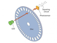
An optical encoder consists of three main components: a light source (typically an LED), an encoder disc with precisely etched slots or patterns, and a photodetector array. The encoder disc is mechanically coupled to the actuator's drive train, rotating as the actuator moves. Light from the LED passes through the slots in the disc and is detected by the photodetector on the opposite side.
As the disc rotates, the slots alternately block and transmit light, creating a series of light pulses that the photodetector converts into electrical signals. High-quality optical encoders can have thousands of slots per revolution, and when geared to the actuator's lead screw, can provide tens of thousands of pulses per inch of linear travel.
Like Hall effect sensors, optical encoders typically provide quadrature output with two channels offset by 90 degrees. This enables direction sensing and doubles the effective resolution by counting both rising and falling edges of both channels. Some advanced optical encoders also include an index pulse—a single pulse per revolution that provides a reference point for more sophisticated positioning algorithms.
Advantages of Optical Encoder Feedback
Optical encoders offer the highest resolution of any feedback technology commonly used in linear actuators. Pulse counts exceeding 20,000 pulses per inch are achievable, providing positioning resolution measured in microns. This extreme precision enables applications in laboratory automation, semiconductor manufacturing, and precision medical devices where even minor positioning errors are unacceptable.
The accuracy of optical encoders is also superior. The precisely manufactured encoder disc ensures that each pulse represents an exact increment of movement, without the variations that can occur in magnetic sensing due to disc magnetization irregularities or external magnetic fields. This consistency is crucial in applications requiring high repeatability over millions of cycles.
Optical encoders are also immune to magnetic interference, making them ideal for applications near motors, transformers, or other sources of magnetic fields that might affect Hall effect sensors. The digital output signal is robust and less susceptible to electrical noise than analog potentiometer signals.
Like Hall effect sensors, optical encoders enable precise multi-actuator synchronization and provide real-time velocity information. They're compatible with advanced motion controllers including FIRGELLI's FA-SYNC-X system, which can leverage the high-resolution feedback to maintain tight synchronization across multiple axes even in demanding applications.
Limitations of Optical Encoder Feedback
The primary drawbacks of optical encoders are cost and environmental sensitivity. Optical encoders are more expensive to manufacture than potentiometers or Hall effect sensors, which increases the overall actuator cost. This premium is justified in precision applications but may be unnecessary for less demanding projects.
Optical encoders can be sensitive to contamination. Dust, oil, or other particles that settle on the encoder disc or the optical path can block light transmission and cause missed pulses or signal errors. While most industrial optical encoders are sealed to prevent contamination, this remains a consideration in extremely dirty or harsh environments where Hall effect sensors might be more robust.
Like Hall effect sensors, optical encoders provide incremental feedback, requiring homing sequences and continuous position tracking. They share all the same implementation considerations regarding power loss, position memory, and initialization procedures.
Comparing Feedback Technologies: Choosing the Right Solution
Selecting the appropriate feedback technology for your linear actuator application requires balancing multiple factors: required positioning accuracy, budget constraints, environmental conditions, control system complexity, and whether absolute or incremental feedback better suits your needs.
Resolution and Accuracy Requirements
If your application requires positioning accuracy better than ±0.1 inches (2.5mm), Hall effect or optical feedback is essential. Potentiometric feedback simply cannot provide sufficient resolution for precision applications. For accuracy requirements in the ±0.01 inch (0.25mm) range, Hall effect sensors are usually adequate. When you need sub-millimeter accuracy or better, optical encoders become the preferred choice.
Consider not just the static positioning accuracy but also repeatability—the ability to return to the same position consistently over many cycles. Incremental feedback systems (Hall effect and optical) generally provide superior repeatability because they're measuring discrete, countable events rather than analog voltages that can drift with temperature and component aging.
Absolute Versus Incremental Positioning
The choice between absolute (potentiometric) and incremental (Hall effect or optical) feedback often hinges on your system's power management and initialization requirements. If your actuator must maintain position memory across power cycles without requiring a homing sequence at startup, potentiometric feedback offers a significant advantage. This is particularly valuable in battery-powered applications or systems where startup time is critical.
However, if your application can accommodate a brief homing sequence at startup—and most can—the superior resolution and accuracy of incremental feedback systems usually outweigh the convenience of absolute positioning. Modern controllers can complete homing sequences in seconds, making this a minor consideration in most applications.
Multi-Actuator Synchronization
Applications requiring synchronized movement of multiple actuators—such as standing desks, large TV lifts, or industrial platforms—benefit significantly from Hall effect or optical feedback. The digital pulse counting provides precise, noise-immune position data that enables tight synchronization even when actuators are fighting different loads.
Potentiometric feedback can work for multi-actuator systems, but achieving perfect synchronization is more challenging due to analog signal variations. Small differences in supply voltage, cable resistance, or potentiometer tolerances can cause the actuators to drift out of sync over time, requiring periodic recalibration.
Environmental Considerations
The operating environment should influence your feedback technology choice. In clean, controlled environments like laboratory equipment or medical devices, optical encoders provide maximum accuracy without environmental concerns. In industrial settings with dust, moisture, or vibration, Hall effect sensors offer an excellent balance of resolution and robustness. For extremely harsh environments with severe electrical noise or electromagnetic interference, potentiometric feedback may be the most reliable option despite its resolution limitations.
Temperature extremes also matter. All three technologies can operate across industrial temperature ranges, but optical encoders may require temperature compensation in precision applications because thermal expansion of the encoder disc can affect accuracy. Hall effect sensors are generally least affected by temperature variations.
Cost and Complexity
Budget constraints often play a significant role in feedback selection. Linear actuators with potentiometric feedback are typically the most economical option, making them ideal for cost-sensitive applications where high precision isn't required. Hall effect feedback represents a mid-range option offering significantly better performance at moderate cost increase. Optical encoders command a premium price justified only when maximum accuracy is necessary.
Control system complexity also varies. Potentiometric feedback requires only analog input capability and simple voltage-to-position conversion. Hall effect and optical feedback require higher processing capability for pulse counting and position tracking, though modern microcontrollers handle this easily. The real complexity comes in implementing robust homing routines and position memory for incremental systems.
Practical Implementation Considerations
Regardless of which feedback technology you choose, successful implementation requires attention to several practical considerations that can make the difference between a reliable system and one that requires constant troubleshooting.
Wiring and Signal Integrity
Proper wiring is crucial for reliable feedback signals. For potentiometric feedback, use shielded cable to minimize electrical noise pickup, especially in environments with motors, variable frequency drives, or other sources of electromagnetic interference. Route feedback cables away from power cables whenever possible, and never run them in the same conduit as high-current motor wiring.
For Hall effect and optical encoders, twisted pair wiring helps maintain signal integrity for the digital pulses. Many industrial controllers provide differential inputs that offer superior noise immunity for encoder signals. Even if your controller uses single-ended inputs, using twisted pair wiring significantly reduces noise-induced errors.
Consider cable length limitations. Long cable runs increase resistance and capacitance, which can degrade analog signals from potentiometers or slow the rise time of digital pulses from encoders. If you must run feedback cables longer than 10-15 feet, consider using line drivers or signal conditioning at the actuator end to maintain signal quality.
Controller Selection and Programming
Your feedback system is only as good as the controller reading it. For potentiometric feedback, ensure your controller's analog-to-digital converter has sufficient bit depth for your accuracy requirements. A 10-bit ADC provides 1024 discrete values, while a 12-bit ADC offers 4096 values—four times the resolution for the same stroke length.
For incremental feedback systems, choose a controller with hardware interrupt capability to ensure no pulses are missed during high-speed movement or when the processor is handling other tasks. Software-based pulse counting that relies on polling can miss pulses if the program is busy with other operations, leading to position errors.
Implement robust error checking in your control software. For potentiometric systems, read the feedback multiple times and average the results to filter out noise. For incremental systems, include limit checking to detect if the pulse count exceeds the actuator's maximum stroke length, which would indicate missed pulses or a counting error.
Power Supply Considerations
Feedback systems require clean, stable power to operate reliably. Use regulated power supplies rather than unregulated wall adapters, especially for potentiometric feedback where the supply voltage directly affects the output signal. If multiple actuators share a power supply, ensure it has sufficient current capacity to avoid voltage sag under load.
Consider providing separate power supplies for the feedback circuits and motor power, particularly in high-current applications. This isolation prevents motor switching noise from contaminating the feedback signals. At minimum, use proper filtering and bulk capacitance on the power supply rails feeding feedback circuits.
Mechanical Considerations
The mechanical installation affects feedback accuracy more than many realize. Ensure the actuator is mounted rigidly with appropriate mounting brackets to prevent flexing or binding that can cause the actual position to differ from the feedback reading. Any mechanical play in the system appears as position error that no amount of feedback sophistication can eliminate.
For applications requiring extreme accuracy, consider that linear actuators have inherent backlash in their gear trains and lead screws. This mechanical dead zone means the actuator must reverse direction and take up the slack before movement begins. High-quality industrial actuators minimize backlash through precision manufacturing, but it's never completely eliminated. Your control algorithm may need to compensate for this by always approaching the final position from the same direction.
Advanced Feedback Applications
Once you've mastered basic position feedback implementation, several advanced techniques can further enhance your actuator system's performance and capabilities.
Velocity and Acceleration Profiling
Incremental feedback systems enable sophisticated motion profiling that extends far beyond simple "move to position" commands. By monitoring the pulse frequency, you can implement closed-loop velocity control, maintaining constant speed regardless of load variations. This is particularly valuable in applications like camera sliders or scanning systems where smooth, consistent motion is critical.
Acceleration and deceleration profiling prevents sudden starts and stops that can cause mechanical stress or disturb sensitive loads. By gradually ramping the motor voltage up and down while monitoring the feedback pulse frequency, you can achieve smooth, controlled motion profiles that improve mechanical life and reduce vibration.
Load Sensing and Stall Detection
Feedback systems enable load sensing by monitoring how actuator speed changes with applied voltage. If the actuator slows significantly despite constant voltage, this indicates increased load. Some control systems use this information to adjust voltage automatically, maintaining constant speed regardless of load variations.
Stall detection is a critical safety feature enabled by feedback. If the controller commands movement but receives no feedback pulses, this indicates the actuator has stalled against an obstruction. The system can immediately stop the motor and raise an error condition, preventing mechanical damage or injury. This capability is particularly important in applications involving human interaction, such as adjustable furniture or medical devices.
Position Memory and Preset Locations
Feedback systems enable sophisticated position memory features. You can program multiple preset positions that the actuator returns to with a single button press or command. This is commonly used in adjustable furniture, camera positioning systems, and industrial machinery where operators need to quickly recall specific positions.
For incremental feedback systems, implementing non-volatile position memory requires careful attention to write endurance of your storage medium. Flash memory has limited write cycles, so implement strategies like only saving position on controlled shutdown rather than continuously updating memory during movement.
Troubleshooting Common Feedback Issues
Even properly implemented feedback systems can exhibit problems. Understanding common failure modes helps you diagnose and resolve issues quickly.
Potentiometric Feedback Problems
Noisy or erratic position readings from potentiometric feedback usually indicate electrical interference or a failing potentiometer. Try adding additional filtering to the signal—a simple RC low-pass filter can eliminate high-frequency noise. If the noise persists, check for poor connections, damaged cables, or deterioration of the potentiometer's resistive element.
Dead spots where the position reading suddenly jumps or becomes unstable indicate worn areas in the potentiometer where the wiper has degraded the resistive track. This typically occurs after hundreds of thousands of cycles and indicates the potentiometer needs replacement.
Incremental Feedback Problems
Position drift in incremental feedback systems—where the reported position gradually becomes incorrect over time—indicates missed pulses. This can result from electrical noise, inadequate controller interrupt handling, or signal integrity issues in long cable runs. Implement more robust noise filtering, ensure your controller prioritizes feedback pulse interrupts, and verify cable quality.
If position drift occurs only at high speeds, your controller may not be fast enough to process all incoming pulses. Either slow the actuator movement speed or upgrade to a faster controller with hardware pulse counting capabilities.
Complete loss of feedback signal indicates a failed sensor, broken wire, or power supply problem. Check that the sensor is receiving proper supply voltage, verify cable continuity, and confirm that the encoder disc or magnetic ring inside the actuator hasn't come loose from the drive shaft.
Conclusion
Selecting the right feedback system for your linear actuator application requires understanding both the technical capabilities of each feedback technology and the specific demands of your application. Potentiometric feedback offers simplicity and absolute positioning for applications where moderate accuracy is sufficient. Hall effect sensors provide the optimal balance of resolution, cost, and reliability for most precision applications. Optical encoders deliver maximum accuracy for the most demanding positioning requirements.
The trend in modern automation increasingly favors digital incremental feedback systems due to their superior resolution and the declining cost of sophisticated controllers that can implement advanced motion control algorithms. However, potentiometric feedback remains highly relevant for applications where absolute positioning without homing is essential.
Regardless of which technology you choose, proper implementation—including appropriate wiring, power supply design, and control algorithms—is just as important as the feedback sensor itself. Taking time to understand these fundamentals will result in a more reliable, accurate, and maintainable motion control system.
Frequently Asked Questions
What is the most accurate feedback option for linear actuators?
Optical encoders provide the highest accuracy and resolution, typically offering 15,000 to 20,000+ pulses per inch of travel. This translates to positioning resolution in the micron range, making them ideal for precision applications like laboratory automation, medical devices, and semiconductor manufacturing. However, Hall effect sensors offer excellent accuracy for most industrial applications at a lower cost, with typical resolutions of 8,000-12,000 pulses per inch. For applications requiring accuracy better than ±0.1mm, either Hall effect or optical feedback is necessary, as potentiometric feedback cannot achieve this level of precision.
Do I need to home my actuator every time I power it on?
This depends on your feedback type. Actuators with potentiometric feedback provide absolute position information and do not require homing—they always know their position even after power loss. However, actuators with Hall effect or optical encoder feedback use incremental position measurement and must establish a known reference position at startup through a homing sequence. Modern controllers can perform homing quickly (typically a few seconds), and the improved accuracy of incremental feedback usually justifies this minor inconvenience. If maintaining position through power cycles is critical and homing is unacceptable, potentiometric feedback is your only option among the three main technologies.
Can I synchronize multiple actuators with different feedback types?
While technically possible, synchronizing actuators with different feedback types is not recommended and significantly increases control system complexity. For reliable multi-actuator synchronization, all actuators should use the same feedback technology—preferably Hall effect or optical encoders. The digital pulse counting from these incremental feedback systems enables precise synchronization even under varying loads. FIRGELLI's FA-SYNC-X controller is specifically designed to synchronize multiple actuators with Hall effect or optical feedback, automatically compensating for load differences to maintain perfect alignment. Attempting to mix potentiometric feedback with incremental feedback would require complex compensation algorithms and would likely never achieve the same synchronization quality.
How do I know how many pulses per inch my actuator provides?
The pulses per inch specification should be provided in your actuator's technical documentation or datasheet. This critical specification determines your system's positioning resolution and must be programmed into your controller for accurate position calculations. If you cannot find this specification in the documentation, contact the manufacturer directly. For FIRGELLI actuators with Hall effect or optical feedback, this information is always provided in the product specifications. You can also determine pulses per inch empirically by commanding a known distance of movement while counting the total pulses received, though this requires careful measurement and may be less accurate than the manufacturer's specification.
What causes position drift in feedback systems and how can I prevent it?
Position drift in incremental feedback systems (Hall effect or optical) occurs when pulses are missed due to electrical noise, inadequate controller processing speed, or signal integrity issues in the feedback wiring. Prevention strategies include using


