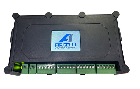
The FIRGELLI FCB-1 control box represents a significant advancement in linear actuator control technology, offering precision synchronization, programmable automation, and intuitive LCD touchscreen operation for up to four actuators simultaneously. Whether you're designing an automated door system, configuring a multi-motor adjustable desk, or implementing a complex motion control solution requiring coordinated movement, understanding the full capabilities of the FCB-1 is essential for achieving reliable, professional-grade results.
This comprehensive operating manual covers everything from initial setup and DIP switch configuration to advanced timer programming and troubleshooting common installation challenges. The FCB-1's ability to synchronize feedback actuators ensures that even under uneven loading conditions, your actuators will maintain precise alignment and coordinated movement—a critical feature for applications like overhead doors, solar tracking systems, or any scenario where multiple actuators must move in perfect unison.
The controller supports both actuators with built-in position feedback (Hall effect or optical sensors) and standard actuators without feedback, making it versatile enough for a wide range of applications. For feedback-equipped actuators, the FCB-1 provides true synchronization, continuously adjusting motor speeds to maintain alignment. For non-feedback actuators, it offers timer-based control and speed adjustment capabilities, extending its utility across your entire actuator inventory.
Critical Pre-Installation: DIP Switch Configuration
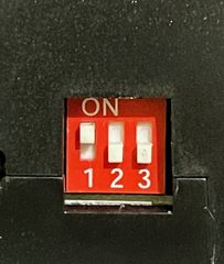
Before connecting power or wiring any linear actuators, you must configure the DIP switches located on the side of the FCB-1 control box. This is the single most common source of setup issues, and incorrect DIP switch settings will prevent the controller from functioning properly, even if all wiring is correct.
The FCB-1 uses three DIP switches to accommodate one to four actuators. The switch position determines how the controller allocates resources and synchronization algorithms. The "up" position indicates ON, while "down" indicates OFF. Here are the correct configurations:
- One Actuator: All DIP switches in the DOWN (OFF) position
- Two Actuators: DIP switch 1 UP (ON), switches 2 and 3 DOWN (OFF)
- Three Actuators: DIP switches 1 and 2 UP (ON), switch 3 DOWN (OFF)
- Four Actuators: All DIP switches in the UP (ON) position
These settings must match the exact number of actuators you're connecting. If you set the switches for four actuators but only connect two, the calibration process will fail. Similarly, connecting four actuators with switches configured for two will result in system errors and red flashing indicators during operation. Always verify DIP switch settings before proceeding to the wiring stage.
Power and Actuator Wiring Guide
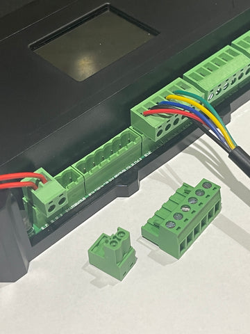
The FCB-1 uses removable green terminal blocks for all connections, making installation and maintenance straightforward. Before beginning the wiring process, remove all green blocks from the controller for easier access. Each connection point is clearly labeled, but understanding the wiring architecture will help prevent errors.
Power Supply Connection
The FCB-1 accepts 12-24VDC input through the small green terminal block located to the left of the M1 (Motor 1) position. The voltage you supply to the controller will be passed through to all connected actuators, so ensure your power supply is rated appropriately for both the controller and the combined current draw of all actuators at their stall current rating.
Connect the positive (+) wire to the left terminal and the negative (-) wire to the right terminal of the power block. If you plan to use an external rocker switch for manual control, add a second positive wire to the same left terminal—this will provide switched power to your control switch. Wire gauge should be selected based on total current draw; for most applications, 18AWG to 16AWG wire is appropriate, but consult your actuator specifications for high-force or high-speed applications.
Actuator Motor Wiring
Each actuator connects via a six-position green terminal block labeled M1 through M4. The leftmost two positions on each block are for the motor power wires. Actuator wire colors vary by model—some use red/black for motor connections, others use blue/brown. Always refer to the wiring diagram on your specific actuator rather than relying on wire color alone.
The terminal positions are typically labeled M+ and M- (or simply + and -), indicating the motor's positive and negative connections. If your actuator runs in the wrong direction after initial testing, simply swap these two motor wires in the terminal block. This is normal and doesn't indicate a wiring error—motor polarity conventions vary among actuator manufacturers.

Feedback Sensor Wiring
For feedback actuators with built-in Hall effect or optical sensors, proper feedback wiring is essential for synchronization functionality. The FCB-1 requires a minimum of three feedback wires, though some actuators provide four wires for differential sensing.
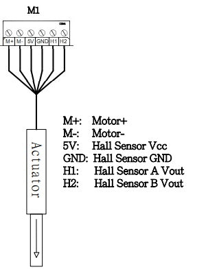
The standard three-wire configuration includes:
- 5V or VCC: Provides power to the feedback sensor (typically red wire)
- GND: Ground reference for the sensor circuit (typically black wire)
- H1 or Signal: The position feedback signal output (color varies—commonly yellow, white, or green)
Four-wire actuators include an additional signal wire (H2, Hall 2, Opt 1, or Opt 2), providing enhanced position resolution. The FCB-1 automatically detects and utilizes this additional signal when present. Ensure all feedback connections are secure in the terminal block—loose feedback wiring is the second most common cause of calibration failures after incorrect DIP switch settings.
External Switch Wiring (Optional)
While the FCB-1's touchscreen provides complete control, many installations benefit from a physical rocker switch for manual operation. To add external switch control, connect the positive power wire from the power terminal (as described earlier) to the center terminal of a DPDT (double-pole, double-throw) rocker switch. The switch outputs then connect to the designated switch terminals on the controller, allowing manual override of automated sequences. This is particularly useful for safety applications or when users need immediate manual control without accessing the LCD interface.
Initial Setup and Calibration Procedure
Once all wiring is complete and DIP switches are correctly configured, power on the FCB-1. The FIRGELLI logo will appear on the LCD screen during the boot sequence. The touchscreen interface responds to finger pressure, but for more precise control, particularly with small buttons, use a stylus, pen cap, or the eraser end of a pencil.
System Configuration
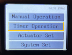
Press the SYSTEM SET button to access system-wide settings. Here you can configure:
- Time and Date: Required for timer-based automation (must be set in 24-hour format)
- Buzzer Settings: Enable or disable audible feedback during operation
- Backlight Adjustment: Optimize screen visibility for your installation environment
Setting the correct time is critical if you plan to use the TIME MODE automation features. The controller uses an internal clock to trigger scheduled movements, and inaccurate time settings will cause your automation schedules to execute at incorrect times.
Actuator Calibration
Calibration is mandatory for proper FCB-1 operation and must be performed before attempting to run actuators. This process allows the controller to learn each actuator's stroke length, speed characteristics, and (for feedback actuators) synchronize their position tracking systems.
To calibrate:
- Press ACTUATOR SET from the main menu
- Press the CAL (Calibration) button
- The controller will automatically extend all connected actuators to their fully extended position
- Actuators will then retract fully to their home position
- Multiple actuators will be synchronized during this process
- Upon successful completion, the controller will emit several clicks and the status LED will flash green
The calibration process typically takes 30 seconds to several minutes, depending on actuator stroke length and speed. Do not interrupt power during calibration. If calibration fails (indicated by a red flashing LED), verify DIP switch settings and all wiring connections before attempting recalibration.
Stroke Length Configuration
After successful calibration, you must enter each actuator's stroke length. This information is typically printed on a label affixed to the actuator body. Even if you're using actuators with position feedback, entering the correct stroke length ensures accurate position display and limit setting.
From the ACTUATOR SET menu, use the numeric keypad to enter the stroke length. The system requires four-digit entry, including leading zeros. For example:
- A 6-inch stroke actuator is entered as: 0600
- A 12-inch stroke actuator is entered as: 1200
- A 2.5-inch stroke actuator is entered as: 0250
Press SAVE to confirm the entry. The display will show the stroke length in inches (or millimeters if you've changed the unit setting in SYSTEM SET).
Advanced Features: Speed and Limit Adjustment
The FCB-1 provides precise control over actuator speed and operating limits, enabling optimization for specific applications and load conditions.
Speed Adjustment
Within the ACTUATOR SET menu, access the speed controls to independently adjust extension and retraction speeds. This dual-speed capability is valuable when your application requires different speeds for each direction—for example, opening a hatch quickly but closing it slowly for safety, or extending an adjustable desk at normal speed but retracting it more quickly for rapid height changes.
Speed adjustment is accomplished through percentage controls, typically from 20% to 100% of the actuator's rated speed. Note that reducing speed also reduces force output slightly, due to the actuator's motor characteristics. For applications requiring full force, maintain speed settings at 80% or higher.
Limit Position Setting
One of the FCB-1's most powerful features (available only with feedback actuators) is electronic limit setting. This allows you to define custom start and stop positions that differ from the actuator's built-in mechanical limit switches.
To set custom limits:
- From ACTUATOR SET, press the LIMIT button
- Two arrows appear on a position bar—the bottom arrow represents the retracted limit, the top arrow represents the extended limit
- Slide each arrow to your desired position
- The arrows cannot cross each other
- Press SAVE to confirm
For example, if you're using a 6-inch stroke actuator but your application only requires movement between 0.5 inches and 5.1 inches, you can set those exact limits. The actuator will never extend beyond 5.1 inches or retract below 0.5 inches, regardless of command input. This feature protects mechanical components and enables precise positioning in applications where the full stroke isn't needed or would cause interference.
Timer Automation: Interval Mode
Interval mode enables repetitive automation based on time delays rather than clock time. This is ideal for applications requiring periodic actuation, such as greenhouse ventilation, automatic pet feeders, or industrial processes requiring cyclic operation.

Configuring Interval Mode
To set up interval operation:
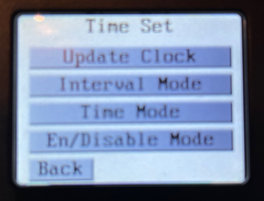
- Press TIMER OPERATION to enter the TIME SET menu
- Select INTERVAL MODE
- Enter the "Delay Until Extend" time in hours:minutes:seconds format (HH:MM:SS)
- Press SAVE
- Enter the "Delay Until Retract" time using the same format
- Press SAVE
Time entry requires two digits for each field, including leading zeros. For example:
- 2 hours = 02:00:00
- 30 minutes = 00:30:00
- 45 seconds = 00:00:45
- 1 hour and 15 minutes = 01:15:00
It's critical to understand that these timers measure idle time, not total cycle time. The "Delay Until Retract" countdown begins only after the actuator has completed its extension movement. Similarly, the "Delay Until Extend" countdown starts only after the actuator has fully retracted. Actuator movement time is not included in the interval periods.
Enabling Interval Mode
After configuring your interval timing, you must explicitly enable the mode:
- From the TIME SET menu, press EN/DISABLE MODE
- Select INTERVAL (it will highlight in yellow when enabled)
- Press BACK twice to return to the main screen
- The program begins running immediately
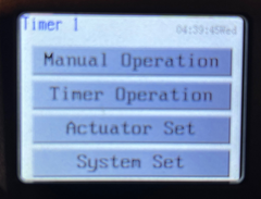
When interval mode is active, "Interval 1" appears at the top of the main screen, confirming the program is running. The actuator(s) will now cycle continuously according to your programmed intervals until you manually disable the mode.
Timer Automation: Time Mode
Time mode provides sophisticated scheduling capabilities, allowing you to program up to five independent timer sequences. Each timer can specify exact times of day, specific days of the week, and independent extend/retract schedules. This makes time mode ideal for applications like automated blinds, solar tracking systems, or any scenario requiring predictable daily or weekly actuation patterns.
Programming Timer Sequences
To create a timed automation sequence:
- Press TIMER OPERATION to access the TIME SET menu
- Select TIME MODE
- Choose a timer slot (TIMER 1 through TIMER 5)
- Enter the "Extend Time Set" using 24-hour format (e.g., 09:00:00 for 9:00 AM)
- Press SAVE
- Enter the "Retract Time Set" (e.g., 16:00:00 for 4:00 PM)
- Press SAVE
- Select the active days by tapping each day you want this timer to run (selected days highlight in yellow)
- Press SAVE

The ability to program five independent timers enables complex scheduling scenarios. For example, you might configure:
- Timer 1: Monday-Friday, extend at 08:00, retract at 17:00 (office hours)
- Timer 2: Saturday, extend at 10:00, retract at 14:00 (weekend schedule)
- Timer 3: Tuesday and Thursday, extend at 12:00, retract at 12:30 (midday ventilation)
Each timer operates independently, and multiple timers can be active simultaneously. The controller handles overlapping schedules intelligently, but for clarity and predictability, it's best to design non-overlapping timer sequences.
Enabling and Managing Timers
After programming your desired timer sequences, enable them through the EN/DISABLE MODE screen:
- From the TIME SET menu, press EN/DISABLE MODE
- Tap each timer number you want to activate (enabled timers highlight in yellow)
- Press BACK twice to begin program execution
The main screen displays active timer status at the top. If multiple timers are enabled, you'll see "Timer 1+2+3" or similar notation. This provides quick visual confirmation of which automation sequences are currently active.
Manual Override Considerations
Even with timers enabled, you retain manual control through the LCD touchscreen's MANUAL OPERATION button or through an external rocker switch if installed. However, activating manual control does not disable timer programs. If you manually extend an actuator at 2:00 PM, but a timer is programmed to retract it at 3:00 PM, the timer will still execute its retract command at the scheduled time.
For maintenance work or testing, it's advisable to temporarily disable all active timers through the EN/DISABLE MODE menu. This prevents unexpected automated movements while you're working with the system.
Troubleshooting Common Installation Issues
Even with careful attention to wiring and configuration, installations occasionally encounter issues. Understanding common failure modes helps resolve problems quickly and avoid unnecessary component replacement.
Actuators Running in Wrong Direction
If one or more actuators extend when they should retract (or vice versa), the motor polarity is reversed. This is not a defect—it simply means the motor wire connections need to be swapped in the green terminal block. Power down the controller, remove the relevant actuator's green block, swap the two motor wires (the leftmost two positions), and reconnect. This reverses polarity and corrects the direction.
In multi-actuator installations, if all actuators run in the wrong direction, you may have reversed the polarity of the power supply itself. Verify that the positive and negative power leads are connected to the correct terminals on the power input block.
One Actuator Not Moving After Calibration
If calibration appears successful (green LED flash) but one actuator remains stationary during operation, the issue is almost always a loose or improperly seated feedback wire. The calibration process can sometimes succeed with marginal connections, but consistent operation requires solid contact.
Troubleshooting steps:
- Power down the system
- Remove the green terminal block for the problematic actuator
- Loosen each terminal screw completely
- Verify each wire is stripped to the appropriate length (1/4 inch of bare conductor)
- Reinsert each wire individually, ensuring it seats fully in the terminal
- Tighten each screw firmly—you should feel resistance, but don't over-torque and strip the terminal
- Gently tug each wire to confirm it's secure
- Reconnect the block and re-run calibration
If the problem persists, test the actuator in isolation. Disconnect all other actuators, set the DIP switches for single-actuator operation (all switches DOWN), and run calibration with just the problematic unit. This isolates whether the issue is with the actuator itself or the multi-actuator configuration.
Red Flashing After Successful Calibration
The most common cause of red status LED flashing after calibration is DIP switch misconfiguration. The calibration process can sometimes complete with incorrect DIP settings, but when you attempt to run the actuators, the controller detects a mismatch between configured and actual actuator count.
Verify your DIP switch settings match the number of connected actuators:
- 1 Actuator: All switches DOWN (OFF)
- 2 Actuators: Switch 1 UP, switches 2 and 3 DOWN
- 3 Actuators: Switches 1 and 2 UP, switch 3 DOWN
- 4 Actuators: All switches UP (ON)
After correcting DIP switch settings, power cycle the controller and re-run calibration. The system needs to re-initialize with the correct configuration.
Intermittent Synchronization Loss
If synchronized actuators periodically lose alignment and the controller flashes red during operation, this usually indicates inconsistent feedback signal quality. Possible causes include:
- Damaged feedback sensor wire (inspect for cuts, pinches, or exposed conductor)
- Electromagnetic interference from nearby motors or high-current wiring (route feedback wires away from motor power leads)
- Failing feedback sensor within the actuator (test with a known-good actuator to isolate)
- Insufficient power supply capacity causing voltage sag under load (verify power supply can deliver rated current to all actuators simultaneously)
Touchscreen Unresponsive
If the LCD touchscreen doesn't respond reliably to touch input, use a stylus, pen cap, or pencil eraser rather than your finger. The resistive touchscreen technology used in the FCB-1 responds best to concentrated pressure on a small surface area. Finger touches, especially with dry skin or in cold environments, may not provide sufficient pressure for reliable detection.
If the touchscreen remains unresponsive even with a stylus, verify the controller is receiving stable power within the 12-24VDC specification. Undervoltage conditions can cause erratic touchscreen behavior.
Application Considerations for Optimal Performance
The FCB-1's advanced synchronization and programming capabilities enable reliable operation in demanding applications, but understanding the controller's operating principles helps optimize system design.
Synchronization and Uneven Loading
When controlling multiple linear actuators in a synchronized application, the FCB-1 continuously monitors position feedback and adjusts individual motor speeds to maintain alignment. This is particularly valuable in applications with uneven loading, such as:
- Overhead doors where one side carries more weight due to off-center placement
- Adjustable desks where users place items unevenly across the surface
- Solar panels where wind loading varies across the array
- Vehicle access ramps where the grade creates varying load conditions
In these scenarios, actuators experience different forces and would normally extend or retract at different speeds, causing misalignment and mechanical stress. The FCB-1 detects when one actuator is moving faster than others and reduces its speed, or increases the speed of slower actuators, to maintain synchronization within tight tolerances (typically ±1mm).
For optimal synchronization performance, use actuators of the same model and specifications. While the FCB-1 can synchronize different actuator types, mixing actuators with significantly different force ratings or speeds reduces synchronization accuracy and may trigger overload protection if the controller cannot maintain alignment.
Power Supply Sizing
When selecting a power supply for FCB-1 applications, calculate total current requirement based on worst-case loading. Each actuator draws maximum current at stall (when blocked or under maximum load). While actuators rarely all stall simultaneously in normal operation, your power supply must handle this scenario to prevent voltage sag and system shutdown.
For example, if you're controlling four actuators, each rated for 6A stall current at 12VDC, your power supply should provide at least 24A continuous at 12VDC. Add 20% headroom for safety: 24A × 1.2 = 28.8A, so a 30A power supply would be appropriate. The FCB-1 controller itself draws minimal current (typically under 500mA), so the calculation is primarily driven by actuator requirements.
Wire Gauge and Voltage Drop
For installations with long wire runs between the controller and actuators, calculate voltage drop to ensure adequate voltage reaches the actuators. Excessive voltage drop reduces actuator force and speed, and can cause the controller to interpret low voltage as a fault condition.
As a general guideline, keep voltage drop under 3% of supply voltage. For a 12V system, this means no more than 0.36V drop; for 24V systems, no more than 0.72V drop. Use online voltage drop calculators or reference wire gauge tables to select appropriate wire size based on your specific current requirements and cable length.
Maintenance and Long-Term Reliability
The FCB-1 requires minimal maintenance, but periodic inspection ensures continued reliable operation:
- Every 6 months: Inspect all terminal block connections for tightness. Thermal cycling and vibration can gradually loosen screw terminals. Re-torque if necessary.
- Annually: Clean the LCD screen with a soft, dry cloth. Avoid liquid cleaners that might seep into the touchscreen assembly.
- As needed: Recalibrate after actuator replacement or if synchronization accuracy degrades over time.
- Environmental protection: While the FCB-1 enclosure provides protection against dust and splash, it's not waterproof. In outdoor or high-humidity applications, install the controller in a NEMA-rated enclosure appropriate for your environment.
Frequently Asked Questions
Can I use the FCB-1 with actuators that don't have feedback?
Yes, the FCB-1 can control standard linear actuators without position feedback sensors. However, without feedback, you lose the synchronization capability—the primary advantage of the FCB-1. You can still control up to four non-feedback actuators simultaneously and utilize the timer functions and speed control features, but the actuators will not be synchronized to each other. They will run at their natural speeds, which may vary due to manufacturing tolerances and load differences. For applications requiring precise alignment, use feedback actuators.
What happens if power fails during timer operation?
The FCB-1 does not have battery backup, so a power loss will cause the controller to shut down immediately. When power is restored, the controller reboots and resumes timer operation based on the current time. However, any movement that was in progress during the power failure will not resume automatically—the actuators will remain in whatever position they were in when power was lost. The next scheduled timer event will execute normally. If your application requires guaranteed completion of movements despite power interruptions, consider adding an uninterruptible


