Effortless Actuator Control: Mastering Time-Based Automation
Industrial automation and precision timing go hand-in-hand in modern manufacturing, material handling, and automated systems. Whether you're operating a production facility, managing agricultural equipment, or building a sophisticated home automation project, the ability to control linear actuators on a timed schedule transforms simple mechanical movement into intelligent, repeatable operations. Time-based actuator control eliminates the need for manual intervention, reduces labor costs, and ensures consistent performance across multiple cycles throughout the day.
🎥 Video — How to set a timer with an actuator - Effortless Actuator Control
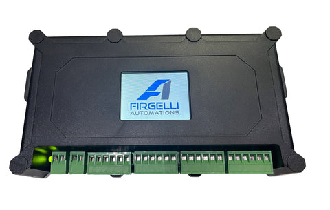
Traditional timer relay systems have served this purpose for decades, but they come with inherent limitations: imprecise mechanical timers, separate power requirements for controllers and actuators, limited programming options, and the complexity of wiring multiple components together. Modern integrated solutions like the FIRGELLI FCB-1 control box address these shortcomings by combining actuator control, timer functionality, and power management in a single unit with an intuitive LCD touchscreen interface.
This comprehensive guide walks you through everything you need to know about setting up timer-based actuator control, from understanding the two primary timing modes to step-by-step programming instructions and real-world application examples.
Understanding Timer Relay Functionality in Actuator Systems
A timer relay is an electronic or electromechanical device that controls the switching of electrical circuits based on preset time intervals or specific times of day. When integrated with linear actuator systems, timer relays enable automated movement cycles without constant human supervision. This functionality is essential for applications ranging from automated ventilation systems that open louvers at specific temperatures and times, to material handling systems that move products through assembly lines at regular intervals.
The FIRGELLI FCB-1 controller distinguishes itself from standalone timer relays by incorporating the timing logic directly into the actuator control board. This integration eliminates compatibility issues between separate components and simplifies wiring considerably. The controller can manage up to four industrial actuators simultaneously, allowing synchronized movement of multiple components—ideal for applications like dual-door systems, coordinated material handling, or multi-point adjustable platforms.
Unlike mechanical timer relays that drift over time and require periodic recalibration, the FCB-1 uses digital timing with crystal oscillator accuracy. This precision ensures that scheduled operations occur within seconds of the programmed time, even after months of continuous operation. The digital interface also provides visual confirmation of programming, reducing setup errors common with mechanical dial-based timers.
Time Mode: Scheduling Actuator Operations by Clock Time
Time mode operates similarly to a programmable thermostat or irrigation controller—you specify exact times during the day when you want the actuator to extend and retract. This mode is ideal for applications tied to business hours, daylight cycles, or scheduled production runs. The FCB-1 controller allows programming of up to five separate time events, each with independent open and close times.
Consider a commercial greenhouse application where automated roof vents need to open at 9:00 AM to allow morning air circulation, close at 11:00 AM during peak sun hours to retain humidity, reopen at 2:00 PM for afternoon ventilation, and close again at 5:00 PM as temperatures drop. With time mode, you program these four transition points once, and the system executes them automatically every day—or only on selected days of the week if preferred.
The day-of-week selection feature proves particularly valuable in industrial settings. A production facility might need automated material handling Monday through Friday but remain idle on weekends. Rather than manually enabling and disabling the system each week, you simply configure which days the timer program should run. This feature also accommodates shift work schedules, where different automated operations occur during first, second, and third shifts.
Time mode programming requires setting the controller's internal clock accurately. The FCB-1 maintains time through a backup battery, ensuring scheduled operations continue even if the main power supply experiences brief interruptions. For critical applications, verifying clock accuracy monthly ensures long-term timing precision.
Interval Mode: Continuous Cycling at Regular Intervals
Interval mode operates independently of clock time, instead functioning as a continuous cycle timer. You specify two parameters: the extension duration and the delay before retraction. Once activated, the controller repeats this cycle indefinitely until manually stopped. This mode excels in applications requiring repetitive motion at consistent intervals regardless of the actual time of day.
Manufacturing assembly lines frequently use interval mode for processes like parts feeding, quality inspection stations, or automated testing equipment. For example, an automotive parts manufacturer might use track actuators in interval mode to advance components along a production line every 45 seconds. Each cycle extends the actuator to push a part forward, holds briefly, then retracts to reset for the next cycle. This continuous operation runs throughout the production shift without requiring time-of-day programming.
Agricultural applications benefit significantly from interval mode. Automated livestock feeders can dispense measured amounts of feed at regular intervals, maintaining consistent feeding schedules that promote animal health. Aquaculture systems use interval-controlled actuators to open feeding hatches every few hours, ensuring fish receive appropriate nutrition throughout the day and night without manual intervention.
The interval timing can be set in seconds, minutes, or hours, providing flexibility for both rapid-cycle applications (like pick-and-place operations occurring every few seconds) and slow-cycle applications (like hourly material handling). The FCB-1's digital timer maintains consistent intervals even under varying electrical loads, unlike mechanical timers whose accuracy degrades with motor startup currents.
Complete Setup Guide: Connecting and Programming Your Timer-Controlled Actuator
Making the Physical Connections
Begin by identifying the connection terminals on the FCB-1 controller. The larger green screw terminals accommodate actuator connections—up to four actuators can connect simultaneously. Smaller terminals handle the power supply input (typically 12V or 24V DC depending on your actuator specifications) and optional external switch connections for manual override capability.
Connect your power supply to the designated terminals, observing proper polarity. Most linear actuators operate on 12V DC, though higher-force industrial actuators may require 24V DC. Verify your actuator's voltage requirements before connecting power. The FCB-1 serves as the power distribution point for all connected actuators, eliminating the need for separate actuator power supplies.
If you plan to use manual override switches alongside automated timer control, connect them to the external switch terminals. This dual-control capability allows operators to manually trigger actuator movement when needed while still maintaining scheduled automatic operations. Wire your actuator to one of the green terminals, ensuring secure connections that won't vibrate loose during operation.
Initial Controller Programming and Calibration
Upon powering the controller, the LCD touchscreen displays the FIRGELLI logo during initialization, then proceeds to the main menu. Access the system settings to configure the internal clock—accurate timekeeping is essential for time mode operations. Set both the current date and time, paying attention to AM/PM designation if using 12-hour format.
Next, configure basic actuator parameters. Select your preferred unit of measurement (inches, millimeters, or centimeters) for stroke length display. Enter the stroke length specification for your connected actuator—this information is available on the actuator's product page or specification sheet. For example, a standard linear actuator might have a 6-inch stroke, while micro linear actuators typically feature shorter strokes between 1 and 4 inches.
The calibration sequence synchronizes the controller with the actuator's physical limits. During calibration, the actuator extends fully, then retracts fully, allowing the controller to establish accurate position tracking. This process typically takes 30-60 seconds depending on stroke length and actuator speed. The touchscreen displays progress and confirms successful calibration completion.
Setting Limits and Speed Control
Limit switches define the actuator's usable travel range. While physical limit switches within the actuator prevent over-extension damage, the controller's programmable limits allow you to restrict travel for specific applications. If your application requires only 4 inches of travel from a 6-inch actuator, set the extended limit to 4 inches. This feature protects mechanical components and ensures the actuator stops precisely where needed.
Speed control adjusts how fast the actuator extends and retracts. The FCB-1 offers independent speed settings for each direction, useful when applications require slow, controlled extension but rapid retraction for increased cycle speed. Speed settings typically range from 10% to 100% of the actuator's maximum rated speed. Lower speeds provide smoother, quieter operation and reduced mechanical stress, extending component life in continuous-duty applications.
Test manual operation before programming timer functions. The touchscreen includes manual control buttons that command extension and retraction. Verify the actuator moves smoothly throughout its range, reaches the set limits correctly, and responds at the programmed speed. This testing phase identifies mechanical binding, insufficient power supply capacity, or wiring issues before implementing automated timing.
Programming Time Mode and Interval Mode
To program time mode, navigate to the timer settings menu and select "Time Mode." The interface displays five programmable events, each with fields for opening time and closing time. Enter your desired schedule using the touchscreen numeric keypad. For each event, specify which days of the week it should execute by selecting from the day-of-week checkboxes. You can create complex schedules like weekday-only operations or alternating-day cycles.
After entering all time events, enable the time mode program through the enable/disable toggle. The controller immediately begins monitoring the clock and will execute programmed events when their scheduled times arrive. A status indicator on the main screen confirms that time mode is active and displays the next scheduled event.
For interval mode programming, select "Interval Mode" from the timer menu. You'll configure three parameters: the time unit (seconds, minutes, or hours), the extension duration, and the retraction delay. For example, a material handling application might use a 10-second extension duration (time for the actuator to push a part forward and hold it in position) followed by a 50-second retraction delay (allowing downstream processes to complete before the next cycle begins). This creates a 60-second total cycle time.
Enable interval mode through the same enable/disable toggle used for time mode. The controller immediately begins the first cycle, extending the actuator according to your programmed parameters. Unlike time mode, interval mode runs continuously once started—it doesn't wait for a scheduled time. Monitor the first few cycles to verify timing matches your application requirements, adjusting parameters as needed.
Real-World Applications of Timer-Controlled Actuators
Manufacturing and Production Line Automation
Automotive component manufacturing relies heavily on timed actuator sequences. Consider a welding station where industrial actuators position parts for robotic welding. Interval mode extends actuators to present parts at precise intervals matching the robot's cycle time, ensuring continuous production flow. Time mode might control shift changes, where automated systems secure all moving components at shift end for safety during personnel transitions.
Electronics assembly facilities use micro linear actuators in interval mode for component insertion operations. The small form factor allows integration into compact assembly stations, while timer control ensures consistent placement rates that match downstream soldering or testing processes. The precision timing eliminates the inconsistency inherent in manual operations, improving quality and throughput.
Agricultural and Greenhouse Applications
Modern greenhouse operations depend on environmental control for optimal plant growth. Timer-controlled actuators manage ventilation openings, adjusting automatically based on time of day and season. During summer, vents might open earlier and close later than winter schedules. The FCB-1's day-of-week programming accommodates maintenance schedules, keeping vents closed during planned system inspections.
Poultry and livestock operations use timed linear actuators for automated feeding and watering systems. Interval mode dispenses feed at regular intervals proven optimal for animal health, while time mode can adjust feeding schedules to match natural feeding patterns—heavier morning and evening feedings with lighter midday portions. This automation reduces labor costs while improving animal welfare through consistent care.
Material Handling and Warehouse Systems
Distribution centers implement timer-controlled actuators in sorting systems. Track actuators extend at precise intervals to divert packages from main conveyor lines to designated shipping lanes. The timing synchronizes with barcode scanners and sorting logic, ensuring packages reach correct destinations. During off-shift hours, time mode can run periodic maintenance cycles, testing actuator function to identify issues before they cause production delays.
Vertical storage systems use timed actuators for automated retrieval. Time mode can pre-position commonly needed items before shift start, reducing initial retrieval delays when workers arrive. Interval mode handles repetitive pick operations during production hours, maintaining consistent throughput rates regardless of operator experience.
Advantages of Integrated Control Over Standalone Timer Relays
Traditional standalone timer relays require external wiring between the relay, power supply, actuator, and any control switches. This complexity increases installation time, introduces multiple potential failure points, and complicates troubleshooting when issues arise. The integrated approach of the FCB-1 consolidates these functions into a single unit, reducing wiring by 60-70% compared to discrete component systems.
Mechanical timer relays drift over time as springs fatigue and gear mechanisms wear. A mechanical timer set for 10-minute intervals might operate at 9:45 after several months, gradually degrading process consistency. Digital timing maintains microsecond-level accuracy indefinitely, ensuring the thousandth cycle executes with the same precision as the first. This reliability is crucial for applications where timing variation affects product quality or safety.
Cost considerations favor integrated controllers for systems controlling multiple actuators. A standalone timer relay typically controls one actuator, requiring additional relays for each actuator added to the system. The FCB-1 manages four actuators simultaneously with a single controller, reducing per-actuator control costs. The ability to synchronize multiple actuators also enables applications impossible with separate timers, like coordinated door systems or multi-point adjustable platforms.
The LCD touchscreen interface eliminates the interpretation errors common with mechanical timer dials. Mechanical timers use small dials with minimal markings, making precise time setting difficult—especially distinguishing between 2:00 AM and 2:00 PM. The FCB-1's digital interface displays exact times and settings in clear numerical format, with separate AM/PM indicators preventing 12-hour errors. The visual feedback confirms programming before activation, a critical safety feature for systems where timing errors could cause equipment damage or safety hazards.
Troubleshooting Common Timer Control Issues
If scheduled events fail to execute, first verify the controller's clock accuracy. Power interruptions longer than the backup battery's capacity will reset the clock, causing all time-based schedules to shift. Check the displayed time against a reliable reference and reset if necessary. Enable/disable status should also be confirmed—time mode programs won't execute if the enable toggle is off, an easy oversight after testing or maintenance.
Actuators that move during programming or testing but fail during automated cycles often indicate limit switch configuration problems. If the actuator reaches a programmed limit before completing its intended motion, it stops prematurely. Review limit settings to ensure they accommodate the full range required by your application. Physical obstructions in the actuator's path will also prevent full travel—verify mechanical clearances allow complete extension and retraction.
Erratic timing or missed cycles in interval mode typically result from insufficient power supply capacity. When multiple actuators operate simultaneously, instantaneous current draw can exceed power supply ratings, causing voltage drops that reset the controller. Calculate total current requirements by adding individual actuator draw figures, then select a power supply rated for at least 25% above this total. This headroom accommodates startup current surges that exceed running current.
Speed variations between cycles suggest mechanical binding or inadequate lubrication in the actuator or load mechanism. Linear actuators require periodic lubrication of the lead screw and internal bearings. Mounting misalignment can also cause binding—verify the actuator's mounting axis aligns with the load's direction of travel. Even slight angular misalignment creates side loads that increase friction and slow movement.
Maintenance and Long-Term Reliability
Timer-controlled actuator systems require minimal maintenance when properly installed, but periodic inspections ensure continued reliability. Monthly verification of clock accuracy prevents timing drift from affecting schedules. Compare the controller's displayed time against a reliable reference and adjust if necessary. Most digital controllers maintain accuracy within seconds per month, but verification is quick insurance against schedule-critical applications.
Quarterly mechanical inspections should check mounting bracket security and alignment. Vibration during operation can loosen fasteners over time. Verify all electrical connections remain tight—screw terminals can work loose due to thermal cycling or vibration. A loose power connection creates intermittent operation that's difficult to diagnose, while a loose actuator connection may cause erratic movement or complete failure.
Annually, update controller firmware if the manufacturer releases improvements. The FCB-1 includes a QR code providing access to the latest instruction manuals and firmware updates. Firmware updates can add features, improve timing accuracy, or address discovered issues. Before updating, document current programming to simplify reconfiguration if settings reset during the update process.
Keep a spare power supply on hand for critical applications. Power supplies are the most common electrical failure point due to continuous operation under varying loads. Having a replacement available minimizes downtime if the primary supply fails. For actuators in harsh environments, consider IP-rated industrial actuators designed for extended service life under demanding conditions.
Achieving Precise Automated Motion Control
Timer-controlled actuator systems transform manual operations into efficient, repeatable automated processes. The choice between time mode and interval mode depends on your application requirements—clock-based scheduling for operations tied to business hours or daylight, continuous cycling for manufacturing processes requiring consistent throughput. The FIRGELLI FCB-1 controller's integrated approach simplifies installation, improves reliability, and provides the flexibility to manage complex multi-actuator systems from a single, intuitive interface.
Whether you're automating industrial material handling, agricultural ventilation, or custom automation projects, understanding timer relay functionality and proper programming techniques ensures your system operates reliably for years. The investment in proper setup and periodic maintenance pays dividends through reduced labor costs, improved consistency, and the freedom to focus on higher-value tasks while your automated system handles repetitive motion control.
Frequently Asked Questions
Can I control multiple actuators with different timer schedules on one controller?
The FCB-1 controller can manage up to four linear actuators simultaneously, but all connected actuators follow the same timer program. If your application requires different schedules for different actuators—for example, one opening at 9 AM while another opens at 10 AM—you'll need separate controllers for each timing sequence. However, if multiple actuators need to move together synchronously, the FCB-1's multi-actuator capability provides perfect coordination impossible to achieve with separate timers.
What happens to my timer schedule if power is interrupted?
The FCB-1 controller includes a backup battery that maintains the internal clock during power interruptions. Brief outages (typically up to several hours depending on battery condition) won't affect your programmed schedules or clock time. However, extended power loss exceeding the backup battery's capacity will reset the clock, requiring you to set the correct time before scheduled operations resume. The timer programs themselves remain in memory—you only need to reset the clock, not reprogram the entire schedule.
Is there a limit to how many cycles an actuator can perform in interval mode?
Interval mode runs continuously without a preset cycle limit—it will repeat indefinitely until manually stopped. However, every linear actuator has a duty cycle rating that specifies the maximum percentage of time it can operate before requiring a cooling period. Continuous operation beyond the duty cycle rating accelerates motor wear and can cause overheating. For continuous-duty applications, select actuators rated for 100% duty cycle, or ensure your interval timing includes sufficient rest periods to stay within the actuator's duty cycle specifications.
Can I manually override the timer program without stopping the entire schedule?
Yes, connecting an external switch to the designated terminals on the FCB-1 controller provides manual override capability. When you trigger the external switch, the actuator responds immediately regardless of the timer schedule. Once manual operation completes, the controller resumes normal timer-based operation according to the programmed schedule. This feature is valuable for applications requiring occasional manual intervention—like maintenance access or emergency operations—without disrupting the overall automated schedule.
How precise is the timing accuracy for scheduled events?
Digital timer controllers like the FCB-1 maintain timing accuracy within a few seconds over extended periods, significantly more precise than mechanical timer relays that can drift by minutes. The crystal oscillator used for timekeeping provides consistent performance regardless of temperature variations or electrical load changes. For most industrial and automation applications, this level of precision is more than adequate. If your application requires sub-second timing accuracy—such as high-speed manufacturing processes—consider using feedback actuators with position control for even greater precision.


