Wireless Control for Modern Motion Systems
The evolution of linear actuator control has moved far beyond simple wired switches. Today's DIY builders, automation enthusiasts, and engineers increasingly demand wireless control solutions that integrate with smartphones and modern home automation ecosystems. Whether you're building a motorized TV lift, automated standing desk, or custom robotic project, Bluetooth-enabled relay modules provide an accessible entry point into wireless linear actuator control.
This comprehensive guide demonstrates how to implement Bluetooth control for electric linear actuators using a two-channel relay module. While the specific TOSR02 V2 module originally featured in this tutorial is no longer available, the fundamental wiring principles and control methods apply universally to any wireless 2-channel, 12V relay unit. This includes modern modules compatible with Alexa, Google Home, and other smart home platforms available through various retailers. The techniques covered here provide a foundation for anyone looking to move beyond FIRGELLI Automation's standard remote control systems toward custom wireless solutions.
Understanding how to properly wire and control relays through Bluetooth interfaces opens the door to sophisticated automation projects. From synchronized multi-actuator systems to computer-controlled motion sequences, mastering these fundamentals enables you to design control systems tailored to your specific application requirements.
Understanding Bluetooth Relay Modules for Actuator Control
A Bluetooth relay module serves as the intermediary between your wireless control device (smartphone, tablet, or computer) and the high-current electrical circuit powering your linear actuators. These modules contain electronically controlled switches (relays) that can handle the substantial current requirements of actuator motors—typically ranging from 2A for small micro linear actuators to 10A or more for larger industrial actuators.
The typical two-channel Bluetooth relay module features two single-pole double-throw (SPDT) relays, each providing three connection points: normally open (NO), common (COM), and normally closed (NC). When de-energized, the relay connects the common terminal to the normally closed terminal. When energized via the Bluetooth control signal, the relay switches the common terminal to the normally open terminal. This switching action is what enables bidirectional control of DC motors in linear actuators.
Most modules operate on 5V logic power (separate from the actuator power supply) and can switch loads up to 10A at 12V or 24V DC. The Bluetooth interface typically operates in the 2.4 GHz range with an effective range of 30-50 feet in open space, though range decreases through walls and interference. Modern modules may also include WiFi capability, enabling integration with home automation systems and control from anywhere with internet access.
Key Specifications to Consider
When selecting a Bluetooth relay module for actuator control, evaluate these critical specifications:
- Relay Current Rating: Must exceed your actuator's peak current draw by at least 20% for reliability and longevity
- Contact Configuration: SPDT (single-pole double-throw) is essential for reversible motor control
- Control Voltage: Typically 5V DC, often supplied via USB or separate power input
- Switching Voltage: Should match your actuator voltage (12V, 24V, etc.)
- Communication Protocol: Bluetooth 4.0 or higher recommended; some offer both Bluetooth and WiFi
- App Compatibility: Verify iOS and Android support if using smartphone control
- API/SDK Availability: Important if developing custom applications
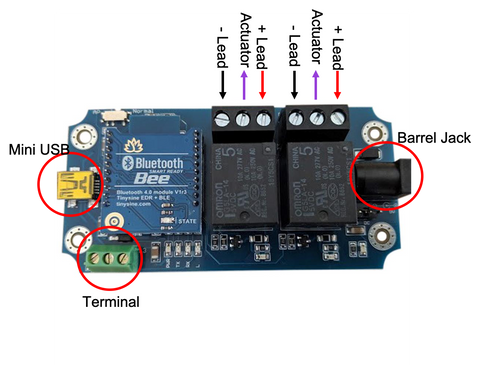
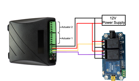
Wiring the Bluetooth Relay Module to Your Linear Actuator
Proper wiring is critical for safe, reliable operation. The configuration uses both relays to create a reversible motor controller—one relay for extending the actuator, another for retracting. This H-bridge-like arrangement allows you to reverse polarity to the actuator motor, changing its direction of movement.
Step-by-Step Wiring Instructions
Follow this wiring sequence carefully to ensure correct operation:
- Connect Actuator Leads to Relay Commons: Connect each of the two wires from your linear actuator to the common (COM) terminal of each relay. These are the middle terminals on most relay modules. It doesn't matter which actuator wire goes to which relay at this stage—this simply determines which relay extends versus retracts.
- Connect Power Supply Positive: Connect the positive (+) lead from your DC power supply to the normally open (NO) terminal of both relays. Use wire splitters or a distribution block if necessary to reach both terminals.
- Connect Power Supply Negative: Connect the negative (-) lead from your power supply to the normally closed (NC) terminal of both relays. Again, you'll need to split this connection to reach both relays.
- Verify Power Supply Voltage: Ensure your power supply matches your actuator's rated voltage (typically 12V or 24V). The supply must also provide adequate current—check your actuator's specifications and add 20% headroom. For example, a 5A actuator requires at least a 6A power supply.
Powering the Relay Module
The relay module itself requires separate 5V DC power for its control electronics and Bluetooth radio. Most modules offer multiple power input options:
- Mini USB Port: Convenient for testing and computer-controlled applications
- Barrel Connector: Standard 5V DC barrel power supplies work well for permanent installations
- Screw Terminal: Allows direct wiring from a 5V power source
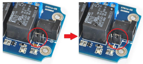
If using a barrel connector or screw terminal power input, you'll typically need to move a jumper on the module from "USB" to "DC" position to select the power source. Consult your specific module's documentation for the exact jumper location.
Important: Never power the relay module from the same high-voltage supply powering your actuators. The 5V control circuit must remain isolated from the higher voltage motor circuit for safety and to prevent damage to the control electronics.
Controlling Your Actuator with a Smartphone
One of the most appealing aspects of Bluetooth relay control is the ability to operate your linear actuator directly from your smartphone without custom programming. Most Bluetooth relay modules include dedicated apps for both iOS and Android platforms, providing immediate control capability out of the box.
Initial Pairing Process
To establish communication between your smartphone and the relay module:
- Download the Module App: Search your device's app store for the app specified in your module's documentation. Common names include "Smart Bluetooth Relay," "BT Relay Control," or manufacturer-specific apps.
- Enable Bluetooth: Ensure Bluetooth is enabled on your smartphone and that you've granted the app necessary permissions to access Bluetooth functionality.
- Power the Module: Connect 5V power to the relay module. Most modules indicate power status with an LED—typically solid red or blue when powered but not yet paired.
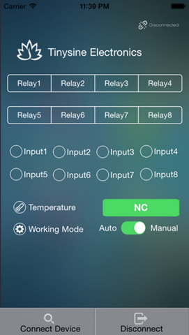
- Scan for Devices: Open the app and initiate a device scan. The module should appear in the list of available Bluetooth devices, often with names like "BT Bee-BLE" (iOS), "BT Bee-EDR" (Android), "HC-05," "HC-06," or similar designations.
- Pair the Device: Select your module from the list. Some modules require a pairing PIN, commonly "0000" or "1234" unless changed in the module settings. Once paired, the connection indicator in the app should change from "disconnected" to "connected."
Operating the Actuator Through the App
Most relay control apps use a simple button interface where each button corresponds to one relay. The relay state is typically indicated by color—blue or green when energized (closed), gray or white when de-energized (open).
To extend or retract your linear actuator:
- Energize One Relay: Tap the button for Relay 1 to energize it (button turns blue/green)
- De-energize the Other: Ensure Relay 2 is de-energized (button gray/white)
- Observe Movement: The actuator should begin moving in one direction
- Reverse Direction: To reverse, de-energize Relay 1 and energize Relay 2
- Stop Movement: De-energize both relays to stop the actuator
Note: If the actuator moves in the opposite direction than desired, you can either swap which relay button you press or physically swap the two actuator wires on the relay common terminals.
Advanced App Features
Many Bluetooth relay apps offer additional functionality beyond basic on/off control:
- Timer Functions: Automatically energize relays for specific durations
- Scheduled Operation: Program actuators to operate at specific times
- Multi-Device Management: Control multiple relay modules from a single app
- Scene Programming: Create preset configurations that activate multiple relays simultaneously
- Password Protection: Prevent unauthorized access to your control system
Computer-Based Control and Automation
For applications requiring programmatic control, data logging, or integration with other systems, computer-based control offers significant advantages over smartphone apps. Most Bluetooth relay modules support serial communication protocols that can be accessed through the USB interface or direct Bluetooth connection from a computer.
USB Serial Connection Setup
Many modules include a USB-to-UART (Universal Asynchronous Receiver-Transmitter) chip that converts USB signals to the serial commands the relay module understands. To use this interface:
- Install Required Drivers: Download and install the USB-to-serial driver for your module's specific chip (common types include CH340, CP2102, or FTDI). These are typically available from the module manufacturer's website or the chip manufacturer.
- Connect via USB: Plug the module into your computer using a mini-USB or micro-USB cable. The operating system should recognize a new serial port (COM port on Windows, /dev/ttyUSB on Linux, /dev/cu.usbserial on macOS).
- Configure Communication Parameters: Set your serial terminal or programming environment to match the module's communication settings, typically: 9600 baud, 8 data bits, no parity, 1 stop bit (9600-8-N-1).
- Test Communication: Send test commands according to the module's protocol documentation to verify connectivity.
Programming Custom Control Software
Once serial communication is established, you can develop custom software in virtually any programming language that supports serial communication. Popular choices include:
- Python: Using PySerial library for straightforward scripting and automation
- C/C++: For high-performance applications or embedded system integration
- Java: With libraries like jSerialComm for cross-platform applications
- LabVIEW: For industrial automation and data acquisition integration
- MATLAB: For research applications requiring data analysis and control
The specific command protocol varies by module but typically involves sending hexadecimal or ASCII commands to switch relays on or off, query relay status, or configure module settings. Always consult your module's technical documentation for exact command sequences.
Automation and Integration Applications
Computer control enables sophisticated automation scenarios:
- Position control when paired with feedback actuators that provide position data
- Sensor-triggered operation (temperature, light, motion sensors)
- Synchronized multi-actuator control for complex mechanisms
- Data logging of actuator operation for maintenance and analysis
- Integration with industrial control systems and PLCs
- Machine vision integration for robotic applications
Controlling Multiple Linear Actuators
Many applications require operating multiple actuators simultaneously—lift systems, adjustable platforms, or synchronized doors. However, directly connecting multiple actuators to a single relay exceeds most modules' current ratings, typically 10A per relay.
Understanding Current Limitations
Each relay channel on standard Bluetooth modules can safely switch approximately 10A at 12V DC. Running two actuators drawing 5A each would push the relay to its absolute maximum, risking overheating, contact welding, or premature failure. This conservative approach to current ratings is essential for reliable long-term operation.
Synchronous Control Board Solution
The proper solution for controlling multiple actuators involves using the Bluetooth relay module as a low-current control signal source for higher-capacity controllers. FIRGELLI's Synchronous Control Boards provide exactly this capability, allowing multiple linear actuators to move in perfect synchronization while handling much higher combined current loads.
Wiring Bluetooth Relay to Synchronous Control Boards
To integrate a Bluetooth relay module with synchronous control boards:
- Configure the Relay Module: Wire the two relays to mimic a double-pole double-throw (DPDT) rocker switch by connecting the common terminals together, the normally open terminals together, and the normally closed terminals together.
- Connect to Control Board Input: Wire the relay common connections to the input terminals of the synchronous control board. This provides the directional control signal without carrying the actuator current.
- Power the Synchronous Board: Connect your main power supply directly to the synchronous control board's power input, not through the Bluetooth relays.
- Connect Actuators: Wire your multiple actuators to the synchronous board's output channels according to the board's documentation.
- Calibrate the System: Follow the synchronous control board's calibration procedure to set the movement range and synchronization parameters. This typically involves running the actuators through their full extension range while the board learns their characteristics.
This configuration allows the low-current Bluetooth relay signals to control the synchronous board, which in turn manages the high-current operation of multiple actuators. The synchronous board ensures all connected actuators move together, compensating for differences in load, friction, or manufacturing tolerances to maintain alignment.
Integration with Smart Home Ecosystems
Modern wireless relay modules increasingly support integration with popular smart home platforms like Amazon Alexa, Google Home, Apple HomeKit, and Samsung SmartThings. This integration elevates actuator control from manual smartphone operation to voice commands and automated routines.
Voice Control Setup
To enable voice control of your linear actuator system:
- WiFi-Enabled Modules: Select a relay module that supports both Bluetooth and WiFi connectivity, with explicit compatibility for your preferred smart home platform
- Cloud Service Registration: Create an account with the module manufacturer's cloud service, which acts as the bridge between your smart home platform and the relay module
- Smart Home Skill Installation: Install the appropriate skill, action, or integration in your smart home platform's app
- Device Discovery: Use your smart home app to discover and add the relay module as a new device
- Naming and Organization: Assign intuitive names like "TV Lift Extend" and "TV Lift Retract" for easy voice control
Creating Automation Routines
Smart home platforms enable sophisticated automation routines that trigger actuator movement based on various conditions:
- Time-Based: Automatically raise a TV lift at 6 PM for evening viewing, lower it at 11 PM
- Sensor-Triggered: Extend window actuators when indoor temperature exceeds a threshold
- Geofencing: Adjust standing desk height when you arrive home
- Scene Integration: Include actuator positions as part of "movie mode" or "presentation mode" scenes
- Cross-Device Automation: Coordinate actuator movement with lighting, audio systems, or security devices
Troubleshooting Common Issues
Connection and Pairing Problems
If you're unable to connect your smartphone or computer to the Bluetooth relay module:
- Verify the module is receiving 5V power (check for power indicator LED)
- Ensure Bluetooth is enabled on your control device
- Move closer to the module—initial pairing often requires proximity within 3-6 feet
- Remove the module from previously paired devices list and re-scan
- Reset the module according to manufacturer instructions (often involves holding a button during power-up)
- Check for Bluetooth interference from other devices or 2.4 GHz WiFi networks
Actuator Doesn't Move
When relays click but the actuator remains stationary:
- Verify the actuator power supply voltage matches actuator requirements
- Check all wiring connections for tightness—loose connections are the most common cause
- Measure voltage at actuator terminals while relay is energized to confirm power delivery
- Test the actuator with direct power connection to rule out actuator failure
- Ensure power supply provides adequate current for your specific actuator model
- Check for blown fuses in the power supply or relay module
Actuator Moves in Wrong Direction
If pressing "extend" causes retraction or vice versa:
- Swap the two actuator wires on the relay common terminals
- Alternatively, switch which relay button controls which direction in your app or code
- For synchronous control boards, use the board's direction reversal setting if available
Intermittent or Unreliable Operation
For inconsistent actuator behavior:
- Check relay current ratings against actuator current draw—relays may be overloaded
- Inspect relay contacts for signs of burning or pitting from arc damage
- Verify all connections use appropriate wire gauge for current being carried
- Add capacitors across actuator terminals to suppress electrical noise
- Ensure adequate power supply capacity with at least 20% headroom above actuator requirements
- Check for voltage drop in long wire runs—use heavier gauge wire if necessary
Safety Considerations and Best Practices
Electrical Safety
When working with relay-controlled actuators, observe these safety guidelines:
- Disconnect Power: Always disconnect all power sources before making wiring changes
- Proper Wire Sizing: Use wire gauge appropriate for current—14 AWG minimum for 10A loads
- Secure Connections: Ensure all screw terminals are tight and wires properly stripped
- Fusing: Install appropriate fuses in the power supply circuit to protect against short circuits
- Insulation: Keep all exposed connections properly insulated with heat shrink or electrical tape
- Enclosure: Mount relay modules in appropriate enclosures to prevent accidental contact
Mechanical Safety
Protect people and property from actuator movement hazards:
- Pinch Point Protection: Install guards or sensors to prevent injury from moving actuators
- Limit Switches: Many linear actuators include internal limits, but verify they function correctly
- Emergency Stop: Implement easily accessible emergency stop capability for powered systems
- Load Ratings: Never exceed manufacturer-specified force and load ratings
- Proper Mounting: Use appropriate mounting brackets and hardware rated for your application
- Movement Visibility: Ensure actuator movement is visible to nearby persons
System Reliability
Design your system for long-term reliable operation:
- Select relays rated for at least 2x the expected number of switching cycles
- Operate actuators within their rated duty cycle—typically 20% or 2 minutes on, 8 minutes off
- Provide adequate ventilation for relay modules and power supplies
- Use shielded cables in electrically noisy environments
- Implement software timeouts to prevent continuous operation if communication is lost
- Regularly inspect connections and components for signs of wear or damage
Conclusion
Bluetooth relay modules provide an accessible, flexible solution for wireless control of electric linear actuators. Whether you're using ready-made smartphone apps for simple control or developing custom computer-based automation systems, understanding the fundamental relay wiring principles and control methods enables you to design sophisticated motion control systems for your projects.
The key to success lies in proper component selection—matching relay current ratings to actuator requirements, choosing modules with appropriate connectivity options for your use case, and implementing safe, reliable wiring practices. For applications requiring control of multiple actuators or higher current capacity, pairing Bluetooth relays with synchronous control boards extends these wireless control capabilities to more demanding applications.
As wireless technology continues evolving, integration with smart home ecosystems and voice control platforms makes linear actuator automation more accessible than ever. Whether you're building a one-off custom project or developing a product for market, these wireless control techniques provide the foundation for creating modern, user-friendly motion control systems.
Frequently Asked Questions
What current rating relay do I need for my linear actuator?
Select a relay rated for at least 20% more current than your actuator's maximum draw. For example, if your actuator draws 8A under full load, use a relay rated for at least 10A. Most micro linear actuators draw 2-5A, while larger industrial actuators may require 6-10A or more. Check your actuator's specifications for exact current draw, which varies with load. Never connect multiple actuators to a single relay unless their combined current remains well below the relay rating.
Can I use a 12V Bluetooth relay with a 24V actuator?
The relay switching voltage rating must meet or exceed your actuator voltage. Most "12V" relay modules can actually switch 12V or 24V DC loads—the "12V" typically refers to the relay coil voltage, not the switching capacity. However, verify your specific module's specifications. The relay contacts must be rated for your actuator's voltage, while the relay module itself is powered by separate 5V DC supply. Never apply actuator voltage directly to the module's 5V power input.
What is the typical range for Bluetooth actuator control?
Standard Bluetooth modules provide approximately 30-50 feet of range in open space with line-of-sight. This range decreases significantly through walls, metal structures, and in environments with WiFi interference. Concrete walls, metal studs, and multiple barriers can reduce range to 10-20 feet. For longer range applications, consider WiFi-enabled modules which work through your home network, or use multiple modules as signal repeaters. Bluetooth 5.0 modules offer extended range up to 100+ feet in optimal conditions.
How do I integrate Bluetooth relay control with Alexa or Google Home?
You need a WiFi-enabled relay module that specifically advertises compatibility with your smart home platform. Pure Bluetooth modules cannot connect directly to Alexa or Google Home—they require WiFi capability. Setup involves: (1) connecting the module to your WiFi network through its companion app, (2) installing the manufacturer's skill or service in the Alexa or Google Home app, (3) discovering devices, and (4) assigning voice-friendly names. Some modules require a cloud service subscription for smart home integration. Always verify compatibility before purchase.
Can I use Bluetooth control with feedback actuators for precise positioning?
Basic Bluetooth relay modules only provide on/off control, not position feedback. However, you can use feedback actuators with more sophisticated control approaches: (1) use a microcontroller like Arduino with Bluetooth module to read position feedback and control relay timing, (2) select advanced motor controllers with built-in Bluetooth and position control capabilities, or (3) implement computer-based control that reads position feedback and calculates appropriate relay timing. Simple relay control alone cannot achieve precise positioning without additional control logic.
Do I need to worry about duty cycle when using Bluetooth control?
Yes, duty cycle remains critical regardless of control method. Most linear actuators are rated for 20% duty cycle, meaning 2 minutes maximum operation followed by 8 minutes rest. This prevents motor overheating. Bluetooth control makes it easier to accidentally exceed duty cycle since operation is so convenient—implement software timeouts or use actuators with built-in thermal protection. For applications requiring continuous or frequent operation, select actuators specifically rated for higher duty cycles (50% or 100%) or use industrial actuators designed for continuous duty.


