
What Is American Wire Gauge (AWG)?
American Wire Gauge (AWG) is a standardized system used in North America to specify the diameter of solid, round, electrically conducting wire. The AWG system uses an inverse numbering scale — a lower AWG number means a thicker wire, and a higher AWG number means a thinner wire. AWG 0000 (also written 4/0) is the thickest standard gauge at 11.684 mm diameter, while AWG 40 is the thinnest at just 0.081 mm.
Understanding wire gauge sizes is essential for anyone working with electrical circuits, whether you’re wiring a home, building a control system for linear actuators, connecting motors, or installing solar panels. Choosing the wrong wire gauge can cause excessive voltage drop, overheating, reduced equipment performance, or fire hazards.
How AWG Numbers Work
The AWG system originated from the number of drawing operations needed to produce a given wire thickness. Thinner wires required more passes through drawing dies, resulting in higher gauge numbers. The key mathematical relationships are:
- Every 3-gauge decrease (e.g., 16 AWG → 13 AWG) doubles the cross-sectional area and halves the resistance
- Every 6-gauge decrease (e.g., 18 AWG → 12 AWG) doubles the diameter and quadruples the area
- Every 10-gauge decrease multiplies the area, weight, and conductance by approximately 10
What Does CMA Mean in Wire Gauge Charts?
CMA stands for Circular Mils Area. A circular mil is a unit of area equal to the area of a circle with a diameter of one mil (one-thousandth of an inch). CMA is calculated as the wire diameter in mils, squared. It’s commonly used in North American electrical codes and specifications alongside mm² for cross-sectional area.
Complete AWG Wire Size Chart — Diameter, Area, Resistance, and Ampacity
The table below is a complete AWG reference covering all standard gauge sizes from 0000 (4/0) through 40 AWG. It includes diameter in both millimeters and inches, cross-sectional area in mm², copper resistance in Ω/km and Ω/1000ft, and maximum ampacity for copper wire in free air.
| AWG | Diameter (mm) | Diameter (in) | Area (mm²) | Resistance (Ω/km) | Resistance (Ω/1000ft) | Max Amps (chassis) | Typical Applications |
|---|---|---|---|---|---|---|---|
| 0000 (4/0) | 11.684 | 0.4600 | 107.2 | 0.161 | 0.0490 | 302 | Service entrance, industrial feeders |
| 000 (3/0) | 10.404 | 0.4096 | 85.03 | 0.203 | 0.0618 | 239 | Service entrance, heavy industrial |
| 00 (2/0) | 9.266 | 0.3648 | 67.43 | 0.256 | 0.0780 | 190 | Subpanel feeders, large motors |
| 0 (1/0) | 8.252 | 0.3249 | 53.48 | 0.322 | 0.0983 | 150 | Subpanel feeders, battery cables |
| 1 | 7.348 | 0.2893 | 42.41 | 0.407 | 0.1240 | 119 | Large motors, welding cable |
| 2 | 6.543 | 0.2576 | 33.63 | 0.513 | 0.1563 | 94 | Central A/C, large appliances |
| 3 | 5.827 | 0.2294 | 26.67 | 0.647 | 0.1970 | 75 | Large appliances, service panels |
| 4 | 5.189 | 0.2043 | 21.15 | 0.815 | 0.2485 | 60 | Furnaces, large heaters, stoves |
| 5 | 4.621 | 0.1819 | 16.77 | 1.028 | 0.3133 | 47 | Heavy-duty appliance circuits |
| 6 | 4.115 | 0.1620 | 13.30 | 1.296 | 0.3951 | 37 | HVAC equipment, welder supply |
| 7 | 3.665 | 0.1443 | 10.55 | 1.634 | 0.4982 | 30 | Specialty equipment circuits |
| 8 | 3.264 | 0.1285 | 8.37 | 2.061 | 0.6282 | 24 | Range, dryer, large appliance circuits |
| 9 | 2.906 | 0.1144 | 6.63 | 2.599 | 0.7921 | 19 | Specialty equipment circuits |
| 10 | 2.588 | 0.1019 | 5.26 | 3.277 | 0.9989 | 15 | 30A circuits, dryers, A/C units |
| 11 | 2.304 | 0.0907 | 4.17 | 4.132 | 1.2600 | 12 | Specialty and lighting circuits |
| 12 | 2.052 | 0.0808 | 3.31 | 5.211 | 1.5880 | 9.3 | 20A household circuits, outlets |
| 13 | 1.828 | 0.0720 | 2.62 | 6.571 | 2.0030 | 7.4 | Specialty wiring |
| 14 | 1.628 | 0.0641 | 2.08 | 8.286 | 2.5250 | 5.9 | 15A household circuits, lighting |
| 15 | 1.450 | 0.0571 | 1.65 | 10.45 | 3.1840 | 4.7 | Specialty and industrial control |
| 16 | 1.291 | 0.0508 | 1.31 | 13.17 | 4.0160 | 3.7 | Extension cords, actuators (<10A) |
| 17 | 1.150 | 0.0453 | 1.04 | 16.61 | 5.0640 | 2.9 | Automotive, low-power electronics |
| 18 | 1.024 | 0.0403 | 0.823 | 20.95 | 6.3850 | 2.3 | Low-voltage lighting, actuator leads |
| 19 | 0.912 | 0.0359 | 0.653 | 26.42 | 8.0510 | 1.8 | Speaker wire, small electronics |
| 20 | 0.812 | 0.0320 | 0.518 | 33.31 | 10.150 | 1.5 | Electronics, small motors, sensors |
| 21 | 0.723 | 0.0285 | 0.410 | 42.00 | 12.800 | 1.2 | Thin electronics wiring |
| 22 | 0.644 | 0.0254 | 0.326 | 52.96 | 16.140 | 0.92 | Telephone wire, data cable, sensors |
| 23 | 0.573 | 0.0226 | 0.258 | 66.79 | 20.360 | 0.729 | Ethernet cable (Cat5e/Cat6) |
| 24 | 0.511 | 0.0201 | 0.205 | 84.22 | 25.670 | 0.577 | Ethernet cable, telephone, data |
| 25 | 0.455 | 0.0179 | 0.162 | 106.2 | 32.370 | 0.457 | Thin telephone and data wiring |
| 26 | 0.405 | 0.0159 | 0.129 | 133.9 | 40.810 | 0.361 | Signal cable, patch cables |
| 27 | 0.361 | 0.0142 | 0.102 | 168.9 | 51.470 | 0.288 | Transformer windings, thin signal |
| 28 | 0.321 | 0.0126 | 0.0810 | 212.9 | 64.900 | 0.226 | Fine electronics, flat ribbon cable |
| 29 | 0.286 | 0.0113 | 0.0642 | 268.5 | 81.840 | 0.182 | Fine motor windings |
| 30 | 0.255 | 0.0100 | 0.0509 | 338.6 | 103.20 | 0.142 | Wire wrapping, thin coil windings |
| 31 | 0.227 | 0.0089 | 0.0404 | 426.9 | 130.10 | 0.113 | Miniature electronics |
| 32 | 0.202 | 0.0080 | 0.0320 | 538.3 | 164.10 | 0.091 | Ultra-fine coils and sensors |
| 33 | 0.180 | 0.0071 | 0.0254 | 678.8 | 206.90 | 0.072 | Precision coil windings |
| 34 | 0.160 | 0.0063 | 0.0201 | 856.0 | 260.90 | 0.056 | Ultra-fine magnet wire |
| 35 | 0.143 | 0.0056 | 0.0160 | 1079 | 328.80 | 0.045 | Ultra-fine magnet wire |
| 36 | 0.127 | 0.0050 | 0.0127 | 1361 | 414.80 | 0.036 | Ultra-fine magnet wire |
| 37 | 0.113 | 0.0045 | 0.0100 | 1716 | 523.10 | 0.028 | Precision instruments |
| 38 | 0.101 | 0.0040 | 0.00797 | 2164 | 659.60 | 0.022 | Precision instruments |
| 39 | 0.090 | 0.0035 | 0.00632 | 2729 | 831.80 | 0.017 | Micro-electronics |
| 40 | 0.081 | 0.0031 | 0.00501 | 3441 | 1049.0 | 0.014 | Micro-electronics |
Resistance values are for copper wire at 20°C (68°F). Ampacity ratings are approximate for single copper conductors in free air at 30°C ambient. Actual ampacity depends on insulation type, installation method, ambient temperature, and number of bundled conductors. Always consult NEC tables (Table 310.16) for code-compliant installations.
How to Choose the Right AWG Wire Size
Selecting the correct wire gauge isn’t just about matching a number to a current rating — it requires considering three factors together:
1. Current (Amperage): Every motor, actuator, and appliance has a rated current draw. The wire must be able to carry this current without exceeding its temperature rating. Check the ampacity column in the table above and select a wire that exceeds your load current with a safety margin.
2. Wire Length (Voltage Drop): Longer wire runs increase resistance, causing voltage to drop before it reaches your load. A motor or actuator designed for 12V that only receives 10.5V due to voltage drop will run slowly, weakly, or not at all. Use our free Voltage Drop Calculator to check whether your wire gauge and length combination stays within acceptable limits.
3. Acceptable Voltage Drop: The NEC recommends keeping voltage drop under 5% for branch circuits. For sensitive electronics, motors, and linear actuators, keeping it under 3% ensures optimal performance.
Common AWG Sizes and Their Typical Uses
| AWG | Typical Current | Common Applications |
|---|---|---|
| 4/0 – 2/0 | 150–302A | Service entrance cables, industrial feeders |
| 1/0 – 2 | 94–150A | Subpanel feeders, battery bank cables, large motors |
| 4 – 6 | 37–60A | Furnaces, stoves, HVAC equipment, EV chargers |
| 8 – 10 | 15–24A | Dryers, A/C units, 30A circuits, shop tools |
| 12 | 9.3A (20A circuit) | Household 20A outlets, kitchen circuits, workshops |
| 14 | 5.9A (15A circuit) | Household 15A lighting and general outlets |
| 16 | 3.7A | Extension cords, linear actuators (<10A), light equipment |
| 18 | 2.3A | Low-voltage lighting, actuator leads, thermostat wire |
| 20 – 22 | 0.9–1.5A | Small motors, sensors, electronics, speaker wire |
| 24 – 26 | 0.36–0.58A | Ethernet cable, telephone, data cable, patch cables |
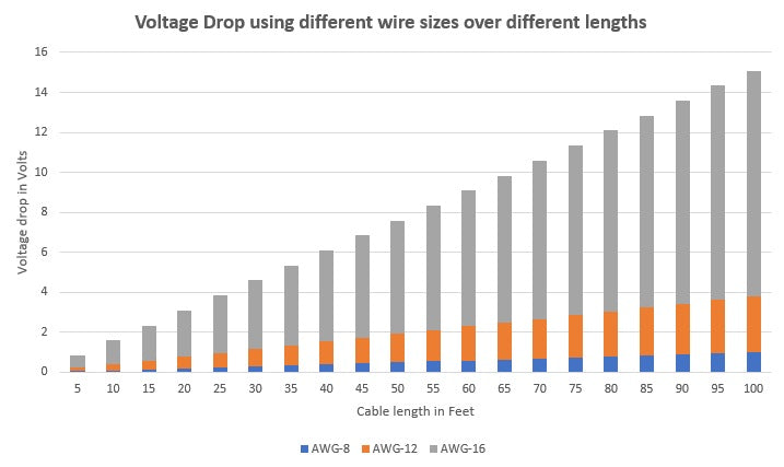
Voltage Drop: Why Wire Length Matters
As electric current travels through a wire, it encounters resistance. This resistance converts some electrical energy into heat and causes a voltage drop — the voltage at the load end of the wire is lower than at the source. The effect is directly proportional to wire length: double the wire length, double the voltage drop.
The formula for voltage drop in a DC circuit is:
Voltage Drop = 2 × Length (ft) × Current (A) × Resistance (Ω/ft)
The factor of 2 accounts for the round-trip distance — current travels out to the load and returns. This is why long runs to motors and actuators can cause significant performance loss even with properly rated wire.
Voltage Drop Example for a Linear Actuator
Suppose you’re powering a 10A linear actuator on 12V with a wire run of 50 feet. If you choose 16 AWG wire (resistance: 4.016 Ω/1000ft):
Voltage Drop = 2 × 50 × 10 × 0.004016 = 4.02V (33.5% drop — far too high)
Stepping up to 10 AWG wire (resistance: 0.9989 Ω/1000ft):
Voltage Drop = 2 × 50 × 10 × 0.0009989 = 1.00V (8.3% drop — much better)
For critical applications, you might go to 8 AWG to bring the drop under 5%. Use our Voltage Drop Calculator to run the exact numbers for your setup.
Wire Gauge for Linear Actuators and 12V Motors
Electric linear actuators and 12V motors have specific wiring requirements that differ from household AC circuits. Most 12V actuators draw between 2A and 10A depending on the load, but some high-force models can draw up to 20A or more at stall.
The key differences for actuator and motor wiring:
- Lower voltage = more sensitive to voltage drop. A 2V drop on a 120V AC circuit is 1.7% — negligible. A 2V drop on a 12V DC circuit is 16.7% — enough to stall an actuator.
- Use stranded wire for actuator connections. Stranded wire handles vibration and flexing better than solid wire, which is critical for moving equipment.
- Account for stall current when sizing wire. An actuator that draws 5A at rated load may draw 15A at stall. Size wire for the higher value.
Recommended Wire Gauges for Common Actuator Setups
| Actuator Current | Short Run (<10 ft) | Medium Run (10–25 ft) | Long Run (25–50 ft) |
|---|---|---|---|
| 2–5A | 18 AWG | 16 AWG | 14 AWG |
| 5–10A | 16 AWG | 14 AWG | 12 AWG |
| 10–20A | 14 AWG | 12 AWG | 10 AWG |
| 20–30A | 12 AWG | 10 AWG | 8 AWG |
These are guidelines for 12V DC circuits with <5% voltage drop. Always verify with a voltage drop calculator for your exact application.
AWG Quick Reference Rules
These rules of thumb are useful for quickly estimating wire requirements without a calculator:
- Every 3 AWG decrease doubles the cross-sectional area. So two 14 AWG wires carry roughly the same current as one 11 AWG wire.
- Every 6 AWG decrease doubles the diameter. A 12 AWG wire is twice the diameter of 18 AWG.
- Double the distance, go down 3 AWG. If 16 AWG works for 10 feet, use 13 AWG (or the next available: 12 AWG) for 20 feet.
- 12V circuits are 10× more sensitive to voltage drop than 120V circuits. Size wire more generously for low-voltage DC applications.
- Stranded wire of the same AWG has the same current capacity as solid wire, but a slightly larger outer diameter due to gaps between strands.
Related Engineering Calculators and Tools
Put these reference tools to work on your next project:
- Voltage Drop Calculator — calculate exact voltage drop for any wire gauge, length, and current
- Torque Calculator & Converter — convert between Nm, lb-ft, lb-in, and kg-cm
- First Class Lever Calculator — calculate actuator force and stroke for lever mechanisms
- Lid & Hatch Actuator Calculator — size actuators for hinged lids, hatches, and pop-top roofs
- Full Calculator Suite — all FIRGELLI engineering calculators in one place
- Arduino Actuator Control Guide — how to control a linear actuator with an Arduino
- Polarity Reversal Guide — how polarity reversal works for motor and actuator direction control


