
How to Replace a Linear Actuator: A Comprehensive Guide
Finding a replacement actuator for your automation project or industrial application can be surprisingly challenging. Whether you're dealing with a discontinued model, a damaged product label, or an actuator from an unknown manufacturer, the task of sourcing an exact replacement often proves impossible. The good news is that with systematic measurement and careful specification matching, you can identify a suitable alternative that will perform just as well—or even better—than your original unit.
This comprehensive guide walks you through the critical parameters you need to evaluate when replacing a linear actuator. We'll cover everything from basic measurements like stroke length and force capacity to more nuanced considerations such as IP ratings and feedback sensor compatibility. Whether you're a DIY enthusiast upgrading a TV lift mechanism or an engineer maintaining industrial equipment, these systematic steps will help you confidently select the right replacement actuator for your application.
Understanding actuator specifications isn't just about finding something that physically fits—it's about matching performance characteristics, environmental requirements, and electrical specifications to ensure reliable, long-term operation. Let's explore each critical parameter in detail.
Step 1: Measuring Actuator Stroke Length
The stroke length is the most fundamental specification of any linear actuator—it defines the total distance the actuator shaft travels from fully retracted to fully extended position. This measurement is non-negotiable; if your stroke length doesn't match your application requirements, the actuator simply won't work, regardless of how well other specifications align.
Measuring a Working Actuator
If your existing actuator is still operational, measuring stroke length is straightforward:
- Fully retract the actuator using its normal power source
- Measure the length of the visible shaft extending from the actuator body
- Fully extend the actuator
- Measure the shaft length again in this extended position
- Calculate the difference between these two measurements—this is your stroke length
For example, if the shaft measures 2 inches when retracted and 14 inches when extended, you have a 12-inch stroke actuator. Most linear actuators are available in standard stroke lengths ranging from 1 inch to 60 inches, with common sizes at 2", 4", 6", 8", 10", 12", 16", 18", 20", and 24".
Measuring When the Actuator Doesn't Work
When dealing with a failed actuator that won't move, you'll need to measure the hole-to-hole dimensions of the application itself:
- Position your mechanism or device in its fully closed position
- Measure the center-to-center distance between the two mounting holes where the actuator attaches
- Manually move the mechanism to its fully open position (if possible)
- Measure the same hole-to-hole distance again
- The difference between these measurements equals your required stroke length
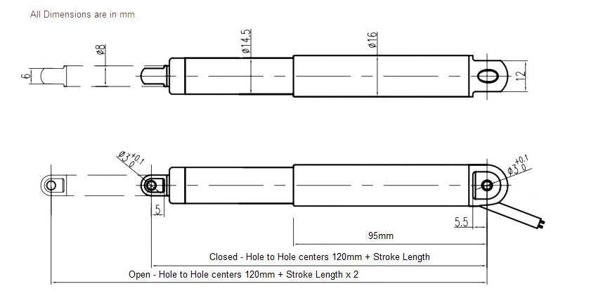
The images below demonstrate proper measurement technique for hole-to-hole dimensions in both fully extended and fully retracted positions:

Linear Actuator measured when fully open

Linear Actuator measured when fully closed
Step 2: Evaluating Force Rating and Speed Characteristics
Once you've determined the stroke length, the next critical specification is force capacity. Linear actuators are rated by how much force they can exert, typically measured in pounds (lbs) or Newtons (N). Understanding both the static force rating and the dynamic speed characteristics is essential for selecting a replacement that performs reliably under load.
Understanding Force Requirements
Force ratings for linear actuators typically range from as little as 1 lb for micro linear actuators to over 2,200 lbs for heavy-duty industrial actuators. The force requirement for your application depends on several factors:
- The weight of the component being moved
- Gravitational forces (lifting versus horizontal movement)
- Friction in the mechanism
- Wind resistance (for outdoor applications)
- Safety factors for reliable operation
A critical engineering principle: never operate an actuator at 100% of its rated capacity. Running actuators at maximum load significantly reduces service life, increases heat generation, and raises the risk of premature failure. Industry best practice suggests sizing actuators to operate at 60-80% of their maximum rated force during normal operation, with the remaining capacity serving as a safety margin.
Using Speed as a Force Indicator
When you can't directly determine force requirements, actuator speed provides valuable clues about force capacity. There's an inverse relationship between speed and force in electric linear actuators—higher force models typically move more slowly, while lower force units operate at higher speeds.
To use speed as a diagnostic tool:
- Measure how quickly your existing actuator extends or retracts under no-load conditions (empty, with nothing attached)
- Time the actuator across its full stroke and calculate inches per second (in/sec) or millimeters per second (mm/sec)
- If possible, measure the speed under your actual working load
- Compare these measurements to manufacturer specifications for candidate replacement actuators
For example, a bullet actuator rated at 200 lbs might move at 0.5 inches per second, while a 50 lb unit of the same stroke length might achieve 2 inches per second. If your existing actuator moves slowly, you likely need a high-force replacement. If it operates quickly, a moderate-force unit may suffice.
Calculating Appropriate Safety Margins
If you've determined your existing actuator's force rating or calculated the actual load requirements, add at least 25% additional capacity when selecting a replacement. For critical applications or harsh operating conditions, consider a 50% or even 100% safety margin. This additional capacity accounts for:
- Load variations and unexpected stresses
- Friction increases as components wear over time
- Environmental factors like temperature extremes
- Acceleration and deceleration forces
- Extended service life through reduced operating stress
Step 3: Confirming Installation Distance and Mounting Configuration
Beyond stroke length, the physical mounting dimensions of your actuator must match your application. The installation distance—often called hole-to-hole distance or retracted length—defines the space the actuator occupies when fully retracted. This measurement is critical because it determines whether the actuator will physically fit in your mechanism.
Measuring Installation Distance
The installation distance is measured from the center of one mounting hole to the center of the other mounting hole when the actuator is fully retracted. This specification varies based on stroke length and actuator design. A 12-inch stroke actuator might have an installation distance of 20 inches, while a 6-inch stroke unit could measure 14 inches when retracted.
To measure installation distance:
- Fully retract the actuator
- Measure from the center point of the mounting hole at the clevis (the shaft end) to the center point of the mounting hole at the actuator body
- Alternatively, measure these same points on your application where the actuator mounts
Some actuators are designed with compact installation distances, particularly useful in space-constrained applications like drawer slides or TV lift mechanisms. Others, especially high-force models, may have longer retracted lengths due to internal gearing and structural requirements.
Mounting Bracket and Hardware Considerations
Different actuator series use various mounting configurations. Common types include:
- Clevis mounts: Universal joints that allow angular movement at both ends, accommodating slight misalignment
- Threaded rod ends: Direct mounting with threaded studs, offering strong connections but requiring precise alignment
- Flat mounting flanges: Common on track actuators, providing wide, stable mounting surfaces
- Custom mounting brackets: May require adapter brackets if your replacement actuator uses a different mounting style than the original
FIRGELLI offers a range of mounting brackets and hardware to adapt various actuator types to different applications, which can be invaluable when the replacement actuator doesn't exactly match the original mounting configuration.
Step 4: Assessing Electrical Power Requirements
Electric linear actuators operate on either alternating current (AC) or direct current (DC), with specific voltage requirements that must match your available power source. Using incorrect voltage can damage the actuator motor and control electronics, or result in poor performance and shortened service life.
DC Voltage Ratings
Most modern linear actuators, particularly those used in automation, automotive, and residential applications, operate on DC power. Common DC voltage ratings include:
- 12VDC: The most common voltage for automotive applications, marine systems, and portable equipment. Ideal for battery-powered operations and compatible with standard automotive electrical systems.
- 24VDC: Preferred in industrial automation and commercial applications where higher power and longer cable runs are required. Offers better efficiency and less current draw than 12V systems with equivalent power output.
- 36VDC and 48VDC: Used in specialized industrial applications and heavy-duty systems requiring higher power delivery with minimal current draw.
DC actuators typically include built-in limit switches that automatically stop the motor when fully extended or retracted, protecting against over-travel damage. They reverse direction by reversing polarity, making them compatible with simple switch controls or sophisticated control boxes and remote controls.
AC Voltage Ratings
AC-powered linear actuators are less common but appear in specific industrial and residential applications. Standard AC ratings include:
- 110-120VAC: North American standard household voltage
- 220-240VAC: International standard and North American commercial voltage
AC actuators typically require more complex control systems and may include internal or external transformers to step down voltage for control circuits.
Current Draw and Power Supply Selection
Beyond voltage, consider the current draw (measured in amperes) of your actuator under load. Higher force actuators draw more current, particularly when moving heavy loads or operating near maximum capacity. When selecting a power supply, ensure it can deliver:
- At least 25% more current than the actuator's maximum rated draw
- Sufficient power for multiple actuators if you're operating them simultaneously
- Stable voltage under load to prevent motor stalling or overheating
Check the label on your existing power supply or measure the current draw with a multimeter during operation to determine your power requirements accurately.
Step 5: Analyzing IP Rating for Environmental Protection
The Ingress Protection (IP) rating is a critical specification that defines an actuator's resistance to solid particles (dust) and liquids (water). Selecting an actuator with an inadequate IP rating for your environment is a common cause of premature failure, particularly in outdoor, marine, or industrial applications.
Understanding IP Rating Codes
IP ratings consist of two digits following the letters "IP":
- First digit (0-6): Protection against solid objects, from no protection (0) to complete dust-tight protection (6)
- Second digit (0-9): Protection against liquids, from no protection (0) to protection against high-pressure, high-temperature water jets (9)
Common IP ratings for linear actuators include:
- IP20-IP42: Basic protection suitable for clean, indoor environments like office furniture, standing desks, or interior TV lifts
- IP54: Protection against dust and water splashing, appropriate for workshops, garages, and semi-protected outdoor installations
- IP65: Dust-tight and protected against water jets, suitable for outdoor applications with weather exposure
- IP66-IP67: Complete dust protection and protection against powerful water jets or temporary immersion, required for marine applications, car washes, or industrial food processing
Matching IP Rating to Your Application
Consider where your actuator operates:
- Indoor, climate-controlled: IP20-IP42 is typically sufficient
- Garage, workshop, or semi-protected outdoor: IP54 minimum recommended
- Fully outdoor, exposed to weather: IP65 or higher
- Marine, submersible, or food processing: IP66-IP67 required
Note that higher IP ratings often come with trade-offs in cost, maintenance requirements, and sometimes performance. Don't over-specify—an IP67 actuator costs significantly more than an IP42 unit and may offer no benefit in a controlled indoor environment.
Step 6: Evaluating Feedback Sensor Requirements
Many modern linear actuator applications require precise position control, synchronization of multiple actuators, or integration with automated control systems. This functionality depends on feedback sensors built into the actuator.
Types of Feedback Sensors
Feedback actuators incorporate position sensing technology to provide real-time information about shaft position. Common types include:
- Potentiometer feedback: A variable resistor provides analog voltage output proportional to position. Simple, cost-effective, and widely compatible with basic control systems.
- Hall effect sensors: Magnetic sensors detect shaft position with high accuracy and durability. Digital output is ideal for microcontroller integration and Arduino projects.
- Optical encoders: High-precision positioning for applications requiring exact, repeatable positioning, common in industrial automation.
Identifying Existing Feedback Configuration
To determine if your existing actuator has feedback sensors:
- Examine the output cable—actuators without feedback have only two wires (positive and negative power)
- Feedback actuators typically have four or more wires: two for motor power, plus additional wires for sensor output and ground
- Check for a separate feedback connector or additional terminals on the actuator body
- Review the original product documentation if available
If your application requires position feedback but your original actuator lacked it, upgrading to a feedback actuator during replacement can significantly enhance functionality, enabling features like:
- Precise position control and programmable stopping points
- Synchronization of multiple actuators to move in perfect unison
- Integration with home automation or industrial control systems
- Position memory for repeatable movements
- Soft-start and soft-stop motion profiles to reduce mechanical stress
Step 7: Using Online Selection Tools to Find Your Replacement
With all specifications documented, you're ready to search for a suitable replacement. FIRGELLI Automations provides an intuitive actuator selection tool that streamlines this process, allowing you to filter thousands of potential options down to the units that meet your specific requirements.

Filtering by Key Specifications
The online selector tool allows you to input:
- Stroke length (in inches or millimeters)
- Force rating (in pounds or Newtons)
- Voltage requirements (12VDC, 24VDC, AC options)
- Speed requirements (inches per second)
- IP rating requirements
- Feedback sensor needs
- Mounting configuration preferences
As you enter each specification, the tool narrows the available options, ultimately presenting a curated list of linear actuators that match your requirements. This systematic approach eliminates guesswork and ensures compatibility.
Comparing Different Actuator Series
FIRGELLI offers several actuator series, each optimized for different applications:
- Bullet actuators: Compact, versatile units for general-purpose applications, available in multiple force ratings and stroke lengths
- Track actuators: High-force units with integrated guide rails for heavy-duty applications requiring stable, side-load resistant operation
- Industrial actuators: Robust, high-capacity units designed for continuous-duty industrial applications
- Micro actuators: Compact, low-force units for space-constrained applications like robotics or small mechanisms
When comparing options, consider not just specifications but also product reviews, duty cycle ratings (percentage of time the actuator can operate continuously), and expected service life for your operating conditions.
Visual Guide: Actuator Replacement Process
For a step-by-step visual demonstration of the actuator replacement process, including measurement techniques and specification identification, watch this comprehensive video guide:
Common Pitfalls When Replacing Actuators
Even with careful specification matching, several common mistakes can compromise your replacement project:
Underestimating Force Requirements
The most frequent error is selecting an actuator with insufficient force capacity. Remember to account for:
- Friction in your mechanism, which increases over time as components wear
- Starting force (static friction), which is typically higher than running force
- Environmental factors like temperature, which can increase friction or reduce motor efficiency
- Safety margins—never plan to operate at 100% capacity
Ignoring Duty Cycle Limitations
All electric motors have duty cycle limitations—the percentage of time they can operate continuously without overheating. A typical duty cycle might be 20%, meaning the actuator can run for 2 minutes, then must rest for 8 minutes. If your application requires continuous or near-continuous operation, you need an actuator rated for high-duty or continuous operation, regardless of force and stroke specifications.
Overlooking Environmental Factors
Temperature extremes affect actuator performance. Cold temperatures increase grease viscosity and reduce motor efficiency, while high temperatures can cause premature wear and failure. If your application operates in extreme conditions, specify actuators rated for extended temperature ranges and consider higher IP ratings for protection against moisture condensation.
Mismatching Speed Expectations
The inverse relationship between force and speed means you can't have both maximum force and maximum speed. If your replacement actuator seems slower than the original, it may be because you've selected a higher force model. Review the force-speed curves in manufacturer specifications to understand this trade-off.
Making the Final Selection
Replacing a linear actuator successfully requires systematic evaluation of multiple interdependent specifications. By carefully measuring stroke length, determining force requirements, confirming installation dimensions, matching electrical specifications, evaluating environmental protection needs, and assessing feedback sensor requirements, you can identify a replacement actuator that performs reliably in your specific application.
The FIRGELLI online selection tool simplifies this process, allowing you to filter options based on your documented specifications and compare suitable alternatives. Whether you're replacing a single actuator in a DIY project or sourcing components for industrial equipment maintenance, this methodical approach ensures compatibility and long-term performance.
Remember that upgrading certain specifications during replacement—such as adding feedback sensors or increasing force capacity—can enhance functionality and extend the service life of your application beyond what the original actuator provided.
Frequently Asked Questions
Can I replace my actuator with the exact same model?
In many cases, this isn't possible. Actuator models are frequently discontinued as manufacturers update product lines with improved designs and technology. Additionally, if the product label is damaged or missing, identifying the exact original model becomes extremely difficult. The good news is that actuators are highly standardized around key specifications like stroke length, force rating, and voltage, making it practical to find a functionally equivalent replacement even if you can't source the identical model. Focus on matching the critical specifications rather than finding an exact model match.
What happens if I choose an actuator with higher force rating than I need?
Using an actuator with higher force capacity than required is generally safe and often beneficial, as it provides a safety margin and typically extends service life by reducing operating stress. The trade-offs are usually higher cost and potentially slower speed, since force and speed are inversely related in electric linear actuators. However, significantly oversizing can be wasteful—a 1000 lb actuator in an application that only requires 50 lbs is unnecessary. A good rule is to size for 25-50% more force than your calculated requirement, giving you adequate safety margin without excessive cost or performance compromise.
How precise does my stroke length match need to be?
Stroke length is the least flexible specification—it must match your application requirements exactly or be slightly longer than needed. If your application requires 10 inches of travel, a 12-inch stroke actuator will work (you simply won't use the full extension), but an 8-inch stroke will not. Most applications can accommodate a slightly longer stroke by limiting travel with external stops or control system programming. However, you cannot make a short-stroke actuator extend farther than its design allows. When in doubt, choose the next longer standard stroke length, but verify that the installation distance (retracted length) still fits within your available space.
Can I use a 24V actuator with a 12V power supply?
No, using voltage significantly different from an actuator's rated voltage will damage the unit or result in poor performance. A 24V actuator powered by 12V will move sluggishly or not at all, fail to develop rated force, and may stall under load, potentially burning out the motor. Conversely, applying 24V to a 12V actuator will cause excessive current draw, overheating, and rapid failure. Always match the voltage rating exactly. If you need to change voltage levels in your application, you must select an actuator designed for your available voltage or install appropriate power supplies to convert to the required voltage.
Should I upgrade to a feedback actuator during replacement?
If your application involves multiple actuators that need to move in sync, requires precise positioning, or would benefit from automation integration, upgrading to a feedback actuator during replacement is highly worthwhile. Feedback sensors enable position monitoring, synchronization, and programmable control that basic actuators cannot provide. The additional cost is modest compared to the functionality gained. However, if your application is simple—like a single actuator that just needs to fully extend and retract—basic limit-switch control may be entirely adequate. Consider whether you need to know the actuator's position at any given moment or control stopping points along the stroke. If yes, feedback is valuable; if no, save the cost.
What if the mounting configuration doesn't match my original actuator?
Mounting configuration differences are typically the easiest challenge to overcome. FIRGELLI offers a comprehensive range of mounting brackets and hardware adapters that can accommodate different mounting styles. For example, you can adapt from threaded rod ends to clevis mounts, or from one clevis size to another. Custom mounting plates can also be fabricated for unique situations. Focus first on matching the critical specifications (stroke, force, voltage), then address mounting adaptation with brackets or hardware modifications. The exception is when installation space is extremely constrained—in those cases, mounting footprint becomes a critical specification that must match closely.
How important is matching the IP rating of my original actuator?
IP rating importance depends entirely on your operating environment. If your actuator operates indoors in a clean, dry environment and your original was rated IP20-IP42, you can safely select any actuator with similar or higher IP rating. However, if your original had IP65 or higher and operates outdoors or in harsh conditions, matching or exceeding that rating is critical to prevent premature failure from water or dust ingress. When uncertain about environmental conditions, choosing a higher IP rating provides insurance against unexpected exposure—the cost difference is usually modest compared to early failure and replacement costs. Never select a lower IP rating than your original if the actuator is exposed to any moisture or dust.
How do I calculate the speed I need for my application?
Actuator speed is typically specified as inches per second (in/sec) or millimeters per second (mm/sec) at no load. To calculate required speed, determine how quickly your mechanism needs to move through its full range of motion. For example, if you need a 12-inch stroke to complete in 30 seconds, you need a minimum speed of 0.4 in/sec (12 inches ÷ 30 seconds). However, remember that actuators slow down significantly under load—a unit rated at 1 in/sec at no load might only achieve 0.5 in/sec when pushing near its maximum force rating. If your application has strict timing requirements, measure your existing actuator's loaded speed or consult force-speed curves in manufacturer specifications to ensure the replacement will meet performance expectations. For most applications, matching the approximate speed of your original actuator is sufficient.


