Wireless Control for Dual Linear Actuator Systems
Whether you're building automated cabinetry, a custom TV lift, adjustable workbenches, or robotic mechanisms, the ability to control multiple linear actuators independently via wireless remote adds tremendous functionality and convenience. The FIRGELLI 4-channel RF remote control system provides professional-grade wireless actuation control that eliminates the need for visible switches, complex wiring runs, or line-of-sight operation constraints.
🎥 Video — How to control two linear actuators using a 4 channel remote control
This comprehensive guide walks you through the complete setup process for controlling two linear actuators using a 4-channel remote control kit. We'll cover everything from basic wiring and programming to switching between momentary and sustained operation modes, adding additional remotes to your system, and safely controlling high-current industrial actuators using relay isolation. By the end of this guide, you'll have the knowledge to implement reliable wireless control for virtually any dual-actuator application.
The RF (radio frequency) technology used in these remote systems operates independently of line-of-sight, meaning you can control your actuators through walls, cabinets, and other obstructions—unlike infrared remotes that require direct visual access. Each of the four channels can be independently controlled, allowing you to operate two actuators with full directional control (extend and retract) while leaving two channels available for future expansion or other devices.
Basic Wiring and Setup for Two Actuators
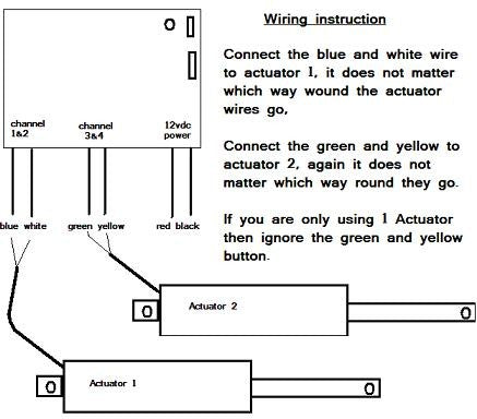
Setting up wireless control for two linear actuators is straightforward when using the FIRGELLI 4-channel remote control kit. The system consists of a handheld RF transmitter (the remote) and a receiver board that interfaces with your actuators and power supply.
The receiver board features four independent relay channels, each capable of switching polarity for bidirectional motor control. For controlling two actuators, you'll use all four channels: channels 1 and 2 control the first actuator's extend and retract functions, while channels 3 and 4 control the second actuator. This configuration provides complete independent control over both actuators.
The wiring process involves connecting your DC power source to the receiver board's power input terminals, then connecting each actuator to its designated channel outputs. The receiver board handles polarity reversal automatically based on which remote button you press, so extend and retract functions work seamlessly without requiring external switching circuitry.
Before beginning installation, ensure your power supply voltage matches your actuators' rated voltage and can supply sufficient current for simultaneous operation if needed. Most standard FIRGELLI actuators operate on 12V DC, though some models support voltage ranges from 12-24V DC for increased speed and force output.
Switching Between Momentary and Sustained Operation Modes
The 4-channel remote control system supports two distinct operating modes that fundamentally change how your actuators respond to button presses: momentary mode and sustained mode. Understanding these modes and knowing how to switch between them allows you to tailor the system's behavior to your specific application requirements.
Momentary Mode Operation
By default, the remote system ships pre-programmed in momentary mode. In this configuration, the actuator moves only while you actively hold down the corresponding button on the remote. The moment you release the button, power to the actuator ceases and motion stops immediately. This mode provides precise control over actuator positioning, making it ideal for applications requiring careful adjustment or where you need to stop at arbitrary positions along the stroke length.
Momentary mode proves particularly useful in applications like adjustable camera platforms, precision positioning systems, or any scenario where you want to "jog" the actuator incrementally. It also serves as a safety feature in applications where automatic full-stroke movement could pose risks.
Sustained Mode Operation
Sustained mode transforms the remote into a "set-and-forget" control system. With a single button press, the actuator begins moving and continues until it reaches its internal limit switch at the end of its stroke, then automatically stops and powers off. This hands-free operation is advantageous for applications like automated doors, TV lifts, or any mechanism where full extension or retraction is the typical use case.
In sustained mode, you don't need to hold the button throughout the entire actuation cycle—simply press and release. The system handles the rest, including automatic shutoff when the actuator's internal limit switches are triggered. This prevents motor stalling and protects both the actuator and the remote control board from damage.
How to Change the Operating Mode
Converting between momentary and sustained modes requires a simple jumper configuration change on the receiver board. Here's the step-by-step process:
- Power down the system: Disconnect the power supply from the receiver board completely before opening the enclosure.
- Open the receiver case: Remove the screws securing the receiver housing to access the circuit board inside.
- Locate the mode jumper: Find the two-pin header with a jumper connecting both pins (momentary configuration).
- Reposition the jumper: Remove the jumper from bridging both pins and place it on just one pin for storage. This changes the configuration to sustained mode.
- Close the case: Secure the receiver housing back together.
- Power cycle the system: Disconnect power if reconnected, wait a few seconds, then restore power. This resets the receiver and activates the new operating mode.
The power cycling step is essential—the receiver must fully reset to recognize the new jumper configuration. Simply changing the jumper position without removing and reapplying power will not activate the mode change.

Programming Additional Remotes to Your System
One of the most valuable features of the FIRGELLI RF remote control system is the ability to program multiple transmitters to work with a single receiver. This allows you to have remote controls in different locations or provide multiple users with independent access to the actuator system—perfect for applications like shared workshop equipment, home automation systems, or commercial installations.
The programming process uses a learning mode that allows the receiver to recognize and store the unique RF signature of each remote transmitter. The receiver board includes a programming button and LED indicator that facilitate this process.
Step-by-Step Programming Procedure
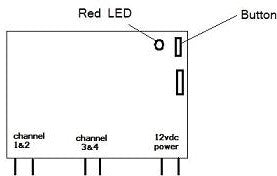
- Access the receiver board: Open the receiver case to access the programming button on the circuit board. The button is typically clearly marked and positioned near an LED indicator.
- Enter programming mode: Press and hold the programming button for approximately 3-5 seconds until the red LED begins flashing. This indicates the receiver is ready to learn new remote codes.
- Program each remote: While the LED is flashing, press any single button on the first remote you want to program. The receiver will capture and store that remote's unique identifier. Wait for the LED to acknowledge the registration (typically a solid light or pattern change).
- Continue with additional remotes: If you have multiple remotes to program, press any button on each subsequent remote, one at a time. You only need to press one button per remote—the system learns the entire remote, not individual buttons.
- Important note on re-programming: When adding new remotes to a system that already has programmed remotes, you must re-program ALL remotes, including the ones that were previously working. The programming mode clears the existing memory and creates a fresh registration list. Program every remote you want to work with the system during the same programming session.
- Exit programming mode: After programming all remotes, remove power from the receiver board completely, wait a few seconds, then reconnect power. This finalizes the programming and resets the receiver to normal operation mode.
- Test all remotes: Verify that each programmed remote successfully controls the actuators. Test all four channels on each remote to ensure complete functionality.
This programming flexibility allows you to scale your control system as your needs evolve. Whether you need two remotes for a home application or a dozen for a commercial installation, the receiver can accommodate multiple transmitters without additional hardware.
Controlling High-Current Actuators Using Relay Isolation
While the 4-channel remote control board provides excellent control for most standard linear actuators, including our Premium and Classic series, the board has a maximum current rating of 5 amps per channel. This limitation poses a challenge when working with high-force industrial actuators that may draw 15-20 amps or more under load.
Connecting a high-current actuator directly to the remote control board will cause immediate and irreversible damage to the board's relay contacts and traces. The solution is to use the remote control board as a low-current signal source that triggers external high-current relays, effectively isolating the delicate control electronics from the heavy power switching requirements.
Understanding Relay Isolation
Relay isolation uses the remote control board to switch small pilot relays or signal relays, which in turn control larger power relays capable of handling high currents. This cascading relay approach protects the control board while enabling control of even the most demanding actuators.
For dual actuator control with high-current devices, you'll need four SPDT (Single Pole, Double Throw) relays rated for at least 20 amps at your system voltage. SPDT relays are essential because they provide both normally-open and normally-closed contacts, allowing you to reverse polarity for bidirectional actuator control.
Required Components
- Four SPDT relays: Minimum 20-amp rating at 12V DC (or your system voltage). Automotive-style relays work well and are readily available.
- Relay sockets or mounting base: For secure relay mounting and easy connection.
- Wire harnesses (optional but recommended): Pre-made harnesses simplify wiring and reduce errors.
- Appropriate gauge wire: Use wire rated for your actuator's current draw—typically 14 AWG or heavier for 20-amp circuits.
- Adequate power supply: Sized to handle the total current draw of both actuators operating simultaneously, with 20-30% overhead for safety.
Wiring Configuration for Relay Isolation
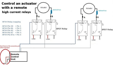
The wiring diagram shows how to properly configure four SPDT relays to provide isolated control for two high-current actuators. The remote control board's outputs connect to the relay coils (the control side), while the actuators and main power supply connect to the relay contacts (the power side).
Each actuator requires two relays for full bidirectional control. For the first actuator, relay 1 controls extension and relay 2 controls retraction. For the second actuator, relay 3 handles extension and relay 4 handles retraction. The SPDT configuration allows each relay to route power with the correct polarity for the desired direction of motion.
Key wiring considerations:
- Relay coil connections: Connect the remote control board's channel outputs to the relay coils. These are low-current connections that the control board can safely handle.
- Power distribution: The main power supply connects to the common terminals of all relays. This provides the high current needed for actuator operation.
- Polarity switching: The normally-open and normally-closed contacts on each relay pair work together to reverse polarity. When relay 1 energizes, the actuator receives positive voltage for extension. When relay 2 energizes, polarity reverses for retraction.
- Expansion capability: The points labeled "A" and "B" in the diagram indicate where additional actuators can be connected in parallel, as long as the total current through each relay doesn't exceed 20 amps.
Installation Best Practices
When implementing relay isolation for high-current actuators, follow these guidelines for reliable, safe operation:
- Use proper terminals: Crimp or solder all connections and use appropriate terminal lugs for relay connections. Loose connections cause voltage drop, heat buildup, and potential fire hazards.
- Mount relays securely: Vibration can cause relay failure or loose connections. Mount relays to a solid surface using appropriate mounting hardware.
- Add fuses: Install appropriately-rated fuses on both the power supply output and each actuator circuit for overcurrent protection.
- Consider diodes: Flyback diodes across relay coils suppress voltage spikes and protect the remote control board. Most automotive relays include internal diodes, but verify before installation.
- Ensure adequate cooling: High-current circuits generate heat. Provide adequate ventilation around relays and wire runs, especially in enclosed installations.
- Test before full installation: Bench test the complete relay circuit with actuators connected before installing in the final application. Verify proper polarity reversal and smooth operation in both directions.
This relay isolation approach isn't limited to the heaviest industrial actuators—it's also valuable when controlling multiple standard actuators in parallel, where the combined current draw might exceed the control board's 5-amp rating.
Common Applications for Dual Wireless Actuator Control
The versatility of wireless dual-actuator control opens possibilities across numerous applications, from home automation to industrial machinery. Understanding common use cases can inspire your own projects and highlight implementation considerations specific to different scenarios.
Home and Office Automation
TV lifts represent one of the most popular home automation applications, where dual actuators provide synchronized lifting for flat-screen displays hidden in furniture or ceiling compartments. The wireless remote allows convenient operation from a couch or bed without visible switches disrupting interior design aesthetics.
Standing desks and adjustable workbenches benefit from independent actuator control, allowing separate height adjustment for different sections or enabling tilt functionality. The sustained operation mode proves particularly useful here, allowing the desk to automatically move to preset heights with a single button press.
Hidden storage compartments, automated cabinet doors, and motorized bookshelf sections add both security and wow-factor to modern homes. Using track actuators for sliding applications provides smooth, quiet operation that wireless control makes effortless.
Automotive and Mobile Applications
Custom vehicle builds frequently incorporate linear actuators for tonneau covers, sliding bed floors, camper pop-tops, and adjustable storage systems. The RF remote's ability to operate through metal and without line-of-sight makes it ideal for vehicle applications where the actuators might be enclosed or located in hard-to-reach areas.
RV and camper modifications often use dual actuators for slide-outs, adjustable beds, or automated storage compartments. The wireless control eliminates the need for dashboard switches or control panels, simplifying installation and maintaining vehicle aesthetics.
Industrial and Commercial Installations
Manufacturing equipment, material handling systems, and automation machinery often require remote positioning control. Using relay isolation with industrial actuators provides the force and reliability needed for heavy-duty applications while maintaining wireless convenience.
Retail displays, trade show booths, and commercial signage use automated actuators for attention-getting motion and space-saving designs. The ability to program multiple remotes means multiple staff members can operate the systems independently.
Robotics and Hobbyist Projects
Custom robotics projects leverage dual actuator control for articulated mechanisms, adjustable platforms, or compound motion systems. Pairing wireless control with feedback actuators enables position monitoring while maintaining wireless operation convenience.
DIY automation enthusiasts use these systems for everything from automated chicken coops to custom telescope mounts, solar panel positioning systems, and motorized garden covers. The momentary mode proves especially useful in precision positioning applications where exact placement matters.
Troubleshooting Common Issues
Even with straightforward installation, occasional issues may arise with wireless actuator control systems. Understanding common problems and their solutions can save significant time and frustration.
Remote Not Responding or Intermittent Operation
If the remote stops working or operates inconsistently, check these common causes:
- Battery condition: Replace the remote's battery even if it appears to have some charge. Weak batteries cause intermittent RF transmission.
- Antenna position: Ensure the receiver's antenna wire is fully extended and not coiled or trapped. A compressed antenna dramatically reduces range.
- RF interference: Other electronic devices, especially those operating on similar frequencies, can interfere with the remote signal. Try relocating the receiver or the interfering device.
- Programming loss: Power surges or electrical noise can occasionally corrupt receiver programming. Re-program all remotes following the procedure outlined earlier.
Actuators Moving in Wrong Direction
If an actuator extends when it should retract or vice versa, the solution is simple: swap the two wires connecting that actuator to the receiver board or relay outputs. Linear actuator direction is determined solely by polarity—reversing the connections reverses the direction.
Actuators Not Moving or Stalling Under Load
When actuators fail to move or stall during operation, consider:
- Power supply capacity: Verify your power supply can deliver adequate current for your actuators, especially when operating both simultaneously. Undersized power supplies cause voltage sag and poor performance.
- Voltage drop: Long wire runs or undersized wire gauge cause voltage drop that robs actuators of power. Use appropriately heavy wire and keep runs as short as practical.
- Binding or mechanical issues: Ensure the actuator moves freely without mechanical binding. Misalignment, inadequate mounting brackets, or excessive side loading can prevent movement even with adequate power.
- Internal limit switch engagement: If an actuator won't move in one direction, it may already be at its stroke limit. Try commanding motion in the opposite direction.
Relay Board or External Relays Overheating
Heat generation indicates excessive current draw or poor connections:
- Current exceeds rating: If the control board feels warm, you may be exceeding the 5-amp per channel limit. Implement relay isolation as described earlier.
- Loose connections: Check all wire connections for tightness. Loose connections create resistance that generates heat and can lead to failure.
- Inadequate ventilation: Ensure the receiver box and any relay enclosures have adequate airflow. Consider adding ventilation holes or relocating to a cooler environment.
Conclusion
Implementing wireless control for dual linear actuator systems transforms static mechanisms into convenient, remotely-operated automation. The FIRGELLI 4-channel RF remote control system provides reliable, professional-grade performance with the flexibility to accommodate a wide range of applications—from home automation projects using standard actuators to industrial installations requiring relay isolation for high-current devices.
The ability to switch between momentary and sustained operation modes allows you to tailor system behavior to your specific needs, while the option to program multiple remotes provides scalability as your requirements evolve. By understanding proper wiring techniques, relay isolation principles, and troubleshooting approaches, you can implement robust wireless actuator control that delivers years of reliable service.
Whether you're building a custom TV lift, automating workshop equipment, or creating a complex robotic mechanism, wireless dual-actuator control provides the functionality and convenience that modern automation demands.
Frequently Asked Questions
How many remotes can I program to work with one receiver?
The FIRGELLI 4-channel receiver can typically store programming for multiple remotes, though the exact number varies by model—most systems support at least 8-10 unique transmitters. Remember that when programming new remotes, you must re-program all existing remotes during the same programming session, as entering programming mode clears the receiver's memory. This ensures all intended remotes are registered together and prevents old, unwanted remotes from maintaining access to the system.
What is the range of the RF remote control system?
RF remote systems typically provide reliable operation up to 100-150 feet (30-45 meters) in open air conditions. The actual range depends on environmental factors including walls, metal structures, and electronic interference. Unlike infrared remotes, RF signals penetrate walls and obstacles, though range decreases through dense materials like concrete or metal. For maximum range, ensure the receiver's antenna wire is fully extended and positioned for optimal signal reception. In most residential and workshop applications, the RF range proves more than adequate even through multiple walls.
Can I control more than two actuators with the 4-channel remote?
Yes, with some wiring modifications. The 4-channel system provides four independent relay outputs, which typically configure as extend/retract control for two actuators. However, you can wire additional actuators in parallel with existing channels if their combined current draw remains under 5 amps per channel (or under the relay rating if using external relays). For example, you could connect two low-current micro actuators to the same channel outputs, allowing them to move together. For independent control of more than two actuators, consider using an 8-channel or 12-channel remote control system.
Do I need external limit switches with this remote control system?
Most FIRGELLI linear actuators include built-in internal limit switches that automatically stop the motor at full extension and retraction, protecting the actuator from damage. When using sustained operation mode, these internal limits are essential—they trigger automatic shutoff when the stroke ends. External limit switches become necessary only in specialized applications where you need to stop the actuator at specific positions before reaching the full stroke, or when using actuators without internal limits. For most standard applications with FIRGELLI actuators, the internal limit switches provide adequate protection without requiring additional components.
What size power supply do I need for two actuators?
Power supply sizing depends on your specific actuators' current draw and whether they'll operate simultaneously. Check your actuator specifications for current draw—typical 12V actuators draw 2-5 amps under load. For two actuators that might run simultaneously, add their individual current draws and add 20-30% overhead for safety and to accommodate startup current surges. For example, two actuators drawing 4 amps each would require approximately 10-12 amps of supply capacity. Always verify that your power supply voltage matches your actuator specifications—most operate on 12V DC, though some support 12-24V ranges for variable speed control.


