First-Class Lever Calculator — Calculate Effort Force Required
A first-class lever is the most versatile type of simple machine. The fulcrum is positioned between the effort and the load, which means a first-class lever can amplify force, amplify speed, or change the direction of force — depending on where the fulcrum is placed. Use the calculator below to determine the exact effort or actuator force required for any first-class lever configuration.

What Is a First-Class Lever?
In a first-class lever, the fulcrum (pivot) is located between the effort force and the load force. The effort force is what you apply (or what the actuator produces), and the load force is the weight or resistance being moved on the other side.
The mechanical advantage (MA) of a first-class lever is:
MA = Effort Arm Distance / Load Arm Distance
What makes first-class levers unique compared to second and third-class levers is that the MA can be greater than 1, equal to 1, or less than 1 depending on where the fulcrum is placed:
- Fulcrum closer to the load → effort arm is longer → MA > 1 → amplifies force (like a crowbar)
- Fulcrum in the center → arms are equal → MA = 1 → balanced (like a seesaw with equal weights)
- Fulcrum closer to the effort → load arm is longer → MA < 1 → amplifies speed and distance (like a catapult)
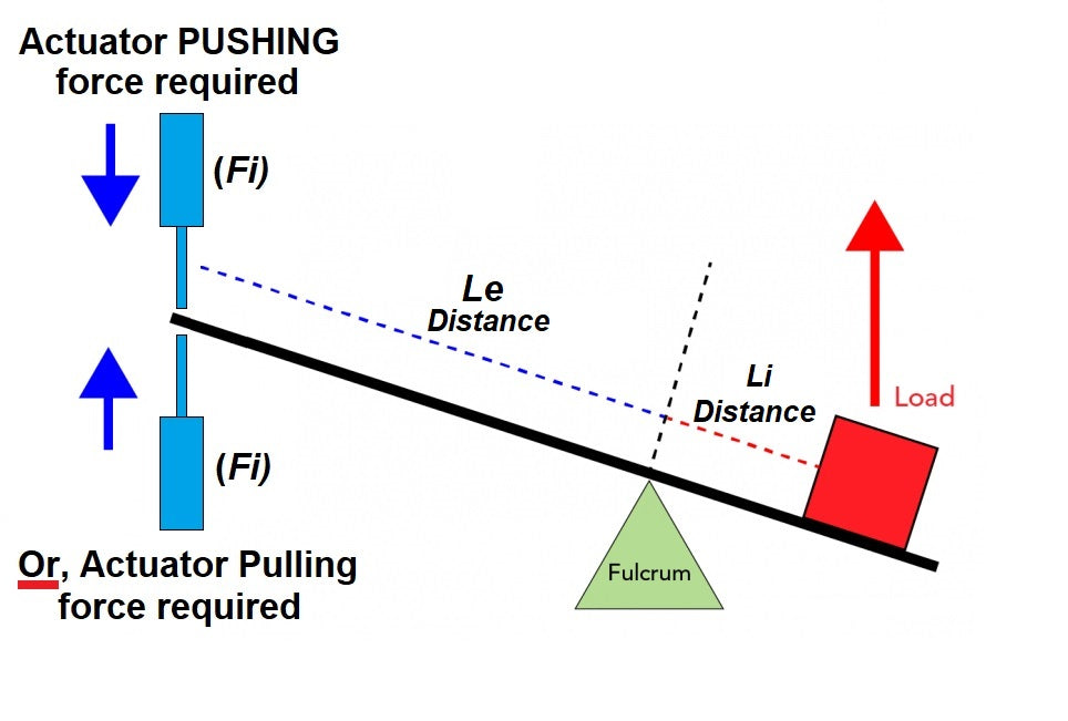
Another unique property: in a first-class lever, the effort and load always move in opposite directions. Push down on one side and the other side goes up. This direction-reversing property is useful when an actuator needs to push in one direction but the load needs to move the opposite way.
Common Examples of First-Class Levers
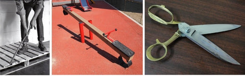
- Seesaw (teeter-totter) — the classic balanced first-class lever; fulcrum in the center, riders on each end
- Crowbar / pry bar — fulcrum near the load end, long effort arm provides high mechanical advantage
- Scissors — the pivot screw is the fulcrum, fingers apply effort on one side, blades cut (load) on the other
- Pliers — same principle as scissors, with the pivot between handles and jaws
- Claw hammer (pulling nails) — the hammer head edge is the fulcrum, handle is the effort arm, claw pulls the nail
- Oars when rowing — the oarlock is the fulcrum, your hands apply effort, the blade pushes water (load)
- Pump handles — the pivot is the fulcrum, you push down on the handle to lift water on the other side
First-Class Lever Force Calculator
Results
Actuator Force Required Fe:
0 lbs
0 N
0 kg
0 g
A different version of a 1st class lever calculator can be found here, that uses a graphical interface to make the calculator clearer.
Click hereThe Formula: How the Calculator Works
The calculator uses the principle of moments (torque balance equation):
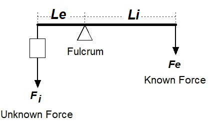
Effort Force (Fe) × Effort Arm (Le) = Load Force (W) × Load Arm (Li)
Rearranged to solve for the effort (actuator force):
Effort Force (Fe) = (Load W × Distance Li) / Distance Le
Where:
- W (Fe in the calculator) = the known load weight on one side of the fulcrum
- Li = the distance from the fulcrum to where the load acts
- Le = the distance from the fulcrum to where the effort force is applied
- Fe (result) = the effort force required on the other side of the fulcrum
Worked Example: Crowbar
You need to pry up a 200 lb concrete slab using a crowbar. The fulcrum (edge of a block) is 6 inches from the slab edge (Li = 6"), and you push down on the crowbar 36 inches from the fulcrum (Le = 36").
Fe = (200 × 6) / 36 = 33.3 lbs of effort required
The mechanical advantage is 36/6 = 6.0 — you only need one-sixth of the load weight. This is why crowbars are so effective: a long effort arm and short load arm create high mechanical advantage.
Worked Example: Seesaw Balance
A 150 lb adult sits 3 feet from the fulcrum on a seesaw. How far from the fulcrum must a 75 lb child sit to balance?
Using torque balance: 150 × 3 = 75 × Le, so Le = 450 / 75 = 6 feet. The lighter child must sit twice as far from the fulcrum to balance the heavier adult.

This is exactly how a playground seesaw works — the fulcrum is in the center, and two weights sit on either side. When one person is heavier, the lighter person must sit farther from the fulcrum to balance. This principle applies identically when sizing an actuator for a first-class lever mechanism.
All Three Lever Classes Compared
| Feature | First-Class Lever | Second-Class Lever | Third-Class Lever |
|---|---|---|---|
| Arrangement | Effort — Fulcrum — Load | Fulcrum — Load — Effort | Fulcrum — Effort — Load |
| Mechanical advantage | Can be >1, =1, or <1 | Always > 1 | Always < 1 |
| Force amplification | Depends on fulcrum position | Always amplifies force | Never amplifies force |
| Direction reversal | Yes (effort and load move opposite) | No (same direction) | No (same direction) |
| Examples | Seesaw, crowbar, scissors | Wheelbarrow, nutcracker, hatch lid | Fishing rod, tweezers, human forearm |
| Actuator use | Counterbalanced platforms, rocking mechanisms | Heavy lids, hatches, trap doors | Fast-moving flaps, gates, robot arms |
First-Class Levers and Linear Actuators
In actuator applications, a first-class lever is used when the linear actuator needs to push on one side of a pivot to move a load on the opposite side. This is common in counterbalanced mechanisms, rocking platforms, and any system where the load direction needs to be reversed relative to the actuator’s push direction.
Positioning the fulcrum closer to the load gives higher mechanical advantage, meaning a smaller actuator can move a heavier load. Positioning the fulcrum closer to the actuator gives speed and distance amplification at the load end.
For more complex geometries where the actuator pushes at an angle, use our interactive graphical calculator:

Related Lever Calculators and Engineering Guides
- Graphical First Class Lever Calculator — interactive visual version with drag-and-drop interface
- Second Class Lever Calculator — load between fulcrum and effort (wheelbarrow, hatch lid)
- Third Class Lever Calculator — effort between fulcrum and load (fishing rod, tweezers)
- Second Class Lever Angled Calculator — when the force is applied at an angle
- Compound Lever Calculator — multiple levers in series for high mechanical advantage
- Lid & Hatch Actuator Calculator — interactive tool for hatch, lid, and pop-top roof actuator sizing
- Scissor Lift Calculator — force and stroke for scissor-lift mechanisms
- Full Calculator Suite — all FIRGELLI engineering calculators in one place
- Types of Linkages Guide — comprehensive guide to all mechanical linkage types
- Mastering Mechanical Advantage — levers, pulleys, gears, and hydraulics explained


