Basics of Linkages: Fundamentals of Levers and Mechanical Linkages
Mechanical linkages convert one type of force or motion into another. They can change direction, amplify force, reduce movement, or make multiple parts move simultaneously from a single input. Every linkage is built from levers — the simplest and most fundamental machine in engineering.
This guide covers the fundamentals of linkages from the ground up: what levers are, how they combine to form linkages, the five basic linkage types, how angles and geometry affect performance, and how to calculate missing angles with our free parallel linkage angle calculator. If you already understand the basics and want to explore advanced mechanisms like four-bar inversions, Grashof's law, and straight-line generators, see our Complete Guide to Types of Linkages.
What Is a Lever?
A lever is a rigid bar that pivots around a fixed point called the fulcrum. When you apply force (called effort) to one end of the lever, it moves a weight or resistance (called the load) at the other end. The lever is one of the six classical simple machines and is the foundation of every linkage mechanism.
Every lever has three components:
- Fulcrum (pivot) — the fixed point the lever rotates around
- Effort — the input force applied to move the lever
- Load — the output force or resistance being moved
The mechanical advantage of a lever depends on the relative distances of the effort and load from the fulcrum. The formula is:
Mechanical Advantage = Effort Arm Length ÷ Load Arm Length
A longer effort arm relative to the load arm means less force is needed to move the load — but the load moves a shorter distance. This trade-off between force and distance is the fundamental principle behind all lever and linkage systems.
The Three Classes of Levers
[Image of the three classes of levers]Levers are classified by the arrangement of the fulcrum, effort, and load. Understanding these three classes is essential because every linkage mechanism is built by combining levers of one or more classes.
| Class | Arrangement | Mechanical Advantage | Examples | Calculator |
|---|---|---|---|---|
| First Class | Fulcrum between effort and load | Can be >1, =1, or <1 | Seesaw, crowbar, scissors, pliers | First-Class Calculator |
| Second Class | Load between fulcrum and effort | Always >1 (force multiplier) | Wheelbarrow, nutcracker, bottle opener | Second-Class Calculator |
| Third Class | Effort between fulcrum and load | Always <1 (speed multiplier) | Fishing rod, human forearm, tweezers | Third-Class Calculator |
When designing linkages with linear actuators, second-class levers are the most common configuration because they amplify the actuator's force — letting a smaller actuator move a heavier load. This is the principle behind actuator-powered lids, hatches, and pop-top camper roofs.
From Levers to Linkages
A single lever can only pivot around its fulcrum. When two or more levers are interconnected by joints, they form a linkage — a mechanism that transmits motion and force between the levers in a controlled way.
The connections between levers in a linkage are made with joints that allow movement:
- Fixed pivots — rotate around a single point but cannot move from that position (like the fulcrum of a seesaw)
- Moving pivots — can move away from their original position as the linkage operates (like the pin connecting a connecting rod to a piston)
- Sliding joints — allow linear movement along a track or slot (like a piston in a cylinder)
Different fasteners connect linkage components while allowing free movement: pins, end-threaded bolts with nuts, clevis pins, and loosely fitted rivets are all common. The choice of fastener affects the smoothness of operation and the load capacity of the linkage.
By changing the number of levers, the length of each lever arm, and the position of the joints, engineers can create linkages that perform a wide range of tasks — from simple direction changes to complex multi-step motions.
The Five Basic Linkage Types
| Linkage Type | What It Does | Direction Change | Common Uses |
|---|---|---|---|
| Reverse-Motion | Output moves opposite to input | 180° | Scissors, seesaws, balance mechanisms |
| Push-Pull (Parallel) | Output moves same direction as input | 0° | Overhead doors, coupled panels |
| Parallel-Motion | Same direction at fixed spacing | 0° | Pantographs, tool trays, train power pickup |
| Bell-Crank | Redirects force by 90° | 90° | Bicycle brakes, steering, aircraft controls |
| Crank-and-Slider | Converts rotary to linear (or reverse) | Rotary ↔ Linear | Engines, pumps, compressors, actuators |
Reverse-Motion Linkage
A reverse-motion linkage makes the output element move in the opposite direction to the input element. It works by using the input link as a lever around a fixed pivot — exactly like a first-class lever.
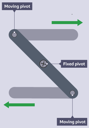
If the fixed pivot is equidistant from both moving pivots, the output movement equals the input movement but in the opposite direction. If the fixed pivot is off-center, the linkage produces mechanical advantage — the output moves a different distance than the input, amplifying or reducing the force depending on which side is longer.
Reverse-motion linkages are used in scissors (the blades move in opposite directions), pliers, and any mechanism where pushing one end needs to create pulling at the other end. This linkage can rotate through a full 360°.
Parallel Motion and Push-Pull Linkages
A parallel-motion linkage (also called a push-pull linkage) makes the output element move in the same direction as the input element while maintaining a constant distance between them.
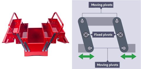
Push-pull linkages are commonly used where linear motion needs to be transmitted without any change in orientation. Overhead doors and gates use this type of linkage to move in a straight line without tilting or rotating. The parallelogram shape formed by the linkage ensures that both the input and output elements stay parallel throughout the stroke.
This linkage is the principle behind pantographs used to pick up electrical power for trains from overhead cables, drawing pantographs for copying diagrams at different scales, and fold-out tool trays that stay horizontal as a toolbox lid opens.
For the best performance, push-pull linkages should be designed with a balanced layout — the input and output elements equally spaced from the pivot points. This ensures smooth and consistent output motion.
Bell-Crank Linkage
A bell-crank linkage redirects force or motion by 90 degrees. It consists of two arms connected at a pivot point, with the arms oriented at a right angle to each other. When force is applied to one arm, the other arm moves perpendicular to it.

Bell cranks are named after the mechanical doorbells they originally powered — a pull rope on one side of a wall would ring a bell on the other side by transmitting the force around a corner.
The most familiar modern example is bicycle rim brakes. Two bell cranks bent 90° in opposite directions are pinned together to form tongs. Squeezing the brake levers (input) pushes the rubber pads (output) inward against the wheel rim. If the pivot is at the midpoint of each crank arm, movement is equal on both sides. Moving the pivot off-center creates mechanical advantage.
Bell cranks are essential in applications where space is limited or where motion needs to be transmitted around an obstacle — steering systems in cars, aircraft control surfaces, and tight-space linear actuator installations all use bell-crank linkages.
Crank-and-Slider Linkage
A crank-and-slider linkage converts rotary motion into linear reciprocating motion, or vice versa. It consists of three elements: a rotating crank, a connecting rod, and a slider that moves back and forth in a straight line.

As the crank rotates, it pushes and pulls the connecting rod, which drives the slider back and forth in a straight line. This is one of the most important mechanisms in engineering — it is the operating principle behind:
- Internal combustion engines — pistons (sliders) push connecting rods that turn the crankshaft (crank), converting linear explosion force into rotary wheel motion
- Reciprocating compressors — a motor turns a crank that drives a piston to compress air or gas
- Linear actuators — a motor (rotary input) turns a lead screw, converting rotation into straight-line extension and retraction
Crank-and-slider linkages can be designed with different crank lengths and slider configurations to achieve different stroke lengths, speeds, and force outputs. The FIRGELLI linear actuator uses a variation of this principle — the motor's rotary motion is converted to linear motion through a lead screw mechanism rather than a traditional crank-and-connecting-rod arrangement.
Treadle Linkage
A treadle linkage converts the linear motion of a foot pedal (treadle) into a different type of motion — typically rotational or reciprocating. The linkage uses a series of levers and pivots to transmit the foot motion to the output mechanism.

When the foot pedal is depressed, it pushes down on a connecting rod. This input is transmitted through a series of levers and pivots that convert the up-and-down pedal motion into continuous rotation of a shaft or back-and-forth reciprocating motion.
The classic example is a sewing machine treadle: pressing the foot pedal moves a connecting rod that pivots a lever, which drives a rotating shaft that powers the needle up and down. Treadle linkages are also found in looms, potter's wheels, and industrial foot-operated machinery.
Treadle linkages can be designed with different input-to-output ratios, allowing the operator to control the speed and intensity of the output motion by adjusting the size and positioning of the lever arms.
Angles in Linkages
Understanding the angles between lever arms is critical for designing linkages that perform correctly. The angle between the lever arm and the direction of the applied force — called the mechanical advantage angle — directly affects how efficiently the linkage transmits force.

In the image above, the top angle is 30°, and therefore the alternate internal angle (Z-angle) at the bottom is also 30°. This relationship is fundamental to understanding how parallel linkages maintain their geometry.
Key Angle Rules for Linkages
- Z-angles (alternate interior angles) — when a line crosses two parallel bars, the angles on opposite sides of the line are equal
- Supplementary angles — two angles on a straight line always add up to 180°
- Corresponding angles — angles in the same position relative to the crossing line and parallel bars are equal
Worked Example: Calculating Angles in a Parallel Linkage

In the diagram above, three angles (A, B, and C) can be calculated for a parallel linkage using the angle rules:
- Angle A = 115°, and it matches 115° on the Z-angle (alternate internal angle rule)
- A and B both sit on a horizontal line, so 115° + B = 180°, therefore B = 65°
- B and C match on a Z-angle, so B and C are both 65°
This is the principle the calculator below uses. If you know any one of the three angles, you can determine the other two.
Parallel Linkage Angle Calculator
Use this calculator to find the missing angle in a parallel linkage. Enter any two known angles and click Calculate — the calculator will determine the third angle (since all three angles in a triangle add up to 180°).
Mechanical Advantage in Linkages
Mechanical advantage is the ratio of the output force to the input force in any lever or linkage system. It tells you how much force amplification (or speed amplification) the linkage provides.
In a simple lever, mechanical advantage is calculated from the arm lengths:
MA = Effort Arm ÷ Load Arm
In a linkage with multiple levers, the overall mechanical advantage is the product of the individual advantages of each lever stage. This is the principle behind compound levers — cascading multiple levers in series to multiply force.
Understanding mechanical advantage helps you size the right actuator for your project. If a linkage provides a mechanical advantage of 3:1, then a linear actuator with 50 lbs of force can move a 150 lb load through that linkage. Conversely, a linkage with mechanical advantage less than 1 (like a third-class lever) trades force for speed — useful when you need fast movement over a large distance.
Design Tip: When the mechanical advantage angle (the angle between the lever arm and the direction of applied force) is too small, the linkage becomes inefficient — most of the force is wasted. When the angle is too large, more force input is needed than necessary. The optimal angle for maximum force transfer is 90° (perpendicular). As the angle deviates from 90°, efficiency drops following a sine function.
Linkages and Linear Actuators
Linear actuators produce straight-line force and motion, but many real-world applications require the force to be redirected, amplified, or applied through an arc. Linkages solve this by connecting the actuator to the load through lever arms and pivot points.
Common linkage configurations used with linear actuators include:
- Second-class lever (lid/hatch) — the actuator pushes on a lever arm to open a hinged lid or hatch, amplifying the actuator's force. Use our Lid and Hatch Calculator to size actuators for this configuration.
- Bell-crank redirect — a bell-crank linkage redirects actuator force 90° for tight-space installations where the actuator cannot be mounted in line with the load direction.
- Parallel-motion linkage — keeps a platform level as actuators raise or lower it, used in scissor lifts and adjustable workstations.
- Crank-and-slider — converts the actuator's linear motion into rotary motion for applications like rotating hatches or swinging arms.
The choice of linkage directly affects the actuator's force requirement, stroke length, and mounting geometry. A well-designed linkage can let you use a smaller, less expensive actuator to move a heavier load.
Next Steps: Advanced Linkage Mechanisms
This guide covers the fundamentals of linkages — the building blocks you need to understand before designing more complex mechanisms. Once you're comfortable with these basics, explore our advanced resources:
- Complete Guide to Types of Linkages — four-bar inversions (crank-rocker, double-crank, double-rocker), straight-line generators (Watt's, Peaucellier), Scotch-yoke mechanisms, Grashof's law, and rotary-to-linear conversion
- First-Class Lever Calculator — calculate actuator force and stroke for first-class lever mechanisms
- Second-Class Lever Calculator — force and stroke for second-class levers (lids, hatches, tonneau covers)
- Third-Class Lever Calculator — force and stroke for third-class levers (speed amplification, fishing-rod-type mechanisms)
- Compound Lever Calculator — cascaded levers for high mechanical advantage
- Scissor Lift Calculator — force and stroke for scissor-lift mechanisms
- Lid and Hatch Actuator Calculator — size actuators for hinged lids, hatches, and pop-top roofs
- Mastering Mechanical Advantage — comprehensive guide to levers, pulleys, gears, and hydraulics
- Full Calculator Suite — all FIRGELLI engineering calculators in one place
- Types of Motion Explained — linear, rotary, reciprocating, and oscillating motion
Frequently Asked Questions About Linkages
A linkage is a system of two or more levers connected by joints to transmit force and motion.
A lever is a single bar. A linkage is a complete mechanism made of multiple levers.
Use the sum of angles in a triangle (180°) and the Z-angle rule for parallel bars.


