Automating Commercial Truck Utility Beds: A Professional Approach to Fleet Efficiency
For commercial electricians, contractors, and fleet operators, accessing tools and equipment quickly can mean the difference between meeting deadlines and losing valuable time. Traditional gas shock-operated toolboxes require manual effort, become difficult to operate when loaded with heavy equipment, and can be challenging to access in tight workspaces or adverse weather conditions. When Ned Richards, co-founder of Richards Electrical in Australia, sought to improve operational efficiency for his fleet, he turned to electric linear actuation as the solution.
🎥 Video — Automated Toolbox - Commercial Truck Utility Bed
By replacing conventional gas shocks with precision-engineered linear actuators, Richards transformed his commercial truck utility beds into automated systems that operate at the press of a button. Using 35-pound force light-duty actuators paired with a four-channel remote control system, his team can now access tools from inside or outside the cab, significantly reducing the physical strain and time required for daily operations. This implementation demonstrates how electric actuation technology, initially developed for aerospace and automotive applications, has become accessible and practical for commercial vehicle automation.
The transition from gas shocks to electric actuators offers several advantages beyond convenience: consistent performance regardless of temperature, precise speed control, enhanced safety features, and the ability to synchronize multiple access points. This guide provides comprehensive technical guidance for implementing similar automation systems in commercial truck utility beds, drawing on real-world installation experience and engineering best practices.
Case Study: Richards Electrical's Automated Fleet Solution
Richards Electrical's implementation serves as an excellent reference point for understanding the practical benefits of toolbox automation. The company selected two 35-pound force actuators to operate a 10-kilogram (22-pound) toolbox door, providing a total static capacity of over 140 pounds. This significant over-specification—using actuators rated for more than six times the actual load—ensures longevity and reliable performance under varying conditions.
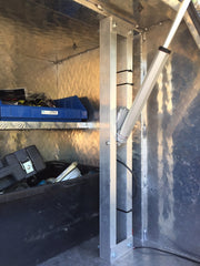
The system achieves an opening speed of approximately two inches per second, which provides smooth, controlled motion that prevents tools from shifting during operation. This deliberate speed selection prioritizes safety and equipment protection over maximum speed. Importantly, Richards maintained the standard locking mechanism on the toolbox doors, demonstrating that automation and security are not mutually exclusive concerns.
For fleet operations like Richards Electrical, which provides prompt electrical services across Australia, the cumulative time savings become significant. When technicians make multiple service calls daily, eliminating even 10-15 seconds per tool access translates to minutes saved per day and hours per week across an entire fleet. Additionally, the system reduces physical strain on workers, potentially decreasing workplace injury rates associated with repetitive lifting and reaching motions.
Replacing Gas Shocks with Linear Actuators: Technical Considerations
Most commercial truck utility boxes and toolboxes come equipped with gas shocks or gas springs from the manufacturer. While these passive systems provide basic assistance, they offer limited control and degrade over time as seals wear and gas pressure decreases. Converting to electric linear actuators provides active control, consistent performance, and remote operation capabilities.
Measuring Stroke Length Requirements
The stroke length represents the total travel distance of the actuator from fully retracted to fully extended position. To determine the required stroke length, measure the existing gas shocks while they are installed on the toolbox. With the door fully closed, note the distance between the mounting points. Then open the door completely and measure again. The difference between these measurements is your required stroke length.
For most truck utility beds, stroke lengths typically range from 6 to 18 inches, depending on the door size and hinge configuration. It's important to note that the stroke length must accommodate the full range of motion without over-extension or bottoming out. Some installations may require slightly shorter stroke lengths than the original gas shocks if the mounting positions are adjusted.
Determining Retracted Length Specifications
The retracted length, measured from mounting hole to mounting hole when the actuator is fully compressed, determines whether the actuator will physically fit in the available space when the door is closed. This measurement is critical because space constraints in truck utility beds are typically tight, with limited clearance between the toolbox and the truck bed floor or sides.
Remove one of the existing gas shocks and fully compress it manually. Measure the overall length from the center of one mounting hole to the center of the other. This dimension, plus any adjustment for different mounting brackets, determines the maximum retracted length your actuator can have. Many installations require actuators with retracted lengths between 10 and 16 inches, though this varies significantly based on toolbox design.
Calculating Force Requirements and Safety Margins
Proper force calculation is essential for actuator longevity and system reliability. Under-specifying force causes actuators to strain, run hot, and fail prematurely. Over-specifying by a reasonable margin ensures smooth operation and accommodates variations in load, friction, and environmental conditions.
To measure the force required, remove both gas shocks and use a force gauge or fish scale attached to the door. Slowly open the door while monitoring the peak force reading. This measurement should be taken at multiple points in the door's travel, as force requirements often vary depending on door position. The highest reading represents your minimum force requirement.
As a best practice, add a 25-50% safety margin to this figure. For example, if your measurement shows 25 pounds of force required, specify actuators rated for 35-40 pounds. This safety margin accounts for increased load when the toolbox is fully stocked, friction from dust and debris, cold weather effects on lubrication, and general wear over time. Richards Electrical's choice of 35-pound actuators for a 22-pound door exemplifies this conservative approach.
Selecting the Right Actuators and Components
With measurements completed, the next step involves matching your specifications to appropriate actuator models. FIRGELLI's product line includes several actuator families designed for different load capacities, environmental conditions, and installation requirements.
Light-Duty Actuators for Standard Toolboxes
For most truck toolbox applications with door weights under 50 pounds, light-duty actuators in the 35-100 pound force range provide adequate performance. These actuators operate on 12V DC power, which can be sourced directly from the vehicle's electrical system, and feature IP65 or IP66 environmental protection suitable for outdoor use.
Light-duty models typically offer stroke lengths from 2 to 18 inches with retracted lengths starting around 10 inches. Speed ranges from approximately 0.5 to 2.0 inches per second, depending on the model and load. The slower speeds actually benefit toolbox applications by preventing sudden movements that could damage tools or injure operators.
Heavy-Duty Actuators for Larger Utility Beds
Larger utility beds with multiple compartments or particularly heavy doors may require industrial actuators rated for 200-500 pounds of force. These heavy-duty units feature reinforced construction, larger diameter lead screws, and more powerful motors. They maintain the same IP65/IP66 environmental ratings but offer significantly higher load capacities and duty cycles.
Heavy-duty actuators may require 24V DC power rather than 12V, necessitating either a voltage converter or a separate 24V battery system. However, this higher voltage enables faster speeds and better performance under load. Installation considerations remain similar to light-duty actuators, though mounting brackets must be appropriately sized for the larger actuator body.
Mounting Brackets and Hardware Selection
Each actuator line has corresponding mounting brackets designed to provide secure attachment and proper alignment. Standard brackets include clevis mounts, flat mounts, and pivot mounts, each suited to different installation geometries. Most truck toolbox conversions use double clevis brackets that attach to both the actuator rod and body, allowing rotational movement at both mounting points.
While FIRGELLI's brackets are designed for straightforward installation, some modification may be necessary to accommodate existing mounting holes or slightly different actuator lengths. The most common modification involves drilling new mounting holes in the toolbox frame or bed structure to position the actuator correctly. Always use stainless steel or zinc-plated hardware to prevent corrosion in outdoor environments.
Control Systems and Electrical Integration
One of the key advantages of electric actuation over gas shocks is the ability to control operation remotely. Several control options exist, each with distinct advantages for truck utility bed applications.
Wireless Remote Control Systems
Wireless remote control systems offer maximum convenience for truck toolbox automation. Two-channel systems can control one pair of actuators (one toolbox door), while four-channel systems can independently control two pairs (two separate doors or a door plus another automated function).
These systems consist of a receiver unit mounted in or near the truck bed, connected to the actuators and power supply, and a compact key fob transmitter. Operating range typically extends to 50-100 feet, allowing operators to open toolboxes while approaching the vehicle or from inside the cab. The receivers feature built-in limit switches that automatically stop actuator motion at the end of travel, preventing over-extension damage.
Richards Electrical's implementation used a four-channel system, providing independent control of both toolbox doors. This configuration allows selective access to different tool compartments without opening the entire utility bed, improving security and weather protection for unused sections.
Wired Control Options: Rocker Switches and Control Boxes
For operators who prefer wired controls or want to mount permanent switches inside the cab, rocker switch systems provide a reliable alternative. These systems use momentary switches connected to a control box that manages actuator direction and limit switching.
Rocker switch installations require routing wires from the switch location to the control box, which then connects to the actuators. While this adds installation complexity compared to wireless systems, wired controls eliminate concerns about battery replacement, signal interference, or lost transmitters. Many fleet operators choose wired systems for these reasons, accepting the additional installation effort for long-term reliability.
Power System Design and Integration
Most 12V actuators can draw 3-8 amps under load, meaning a typical two-actuator setup might require 16 amps of current capacity. This is well within the capability of standard automotive electrical systems, but proper wire sizing and fusing are essential for safety and reliability.
For 12V installations, connect to the vehicle's auxiliary power system using appropriately rated wire (typically 14-16 AWG for runs under 20 feet) and inline fuses rated 20-30% above the expected maximum current draw. Many installers prefer to wire through the truck's existing accessory circuits, which are only powered when the ignition is on, preventing battery drain from accidentally activated actuators.
Heavy-duty 24V actuator systems require either a power supply converter or a separate 24V battery. DC-DC converters that step up 12V vehicle power to 24V are available and work well for moderate-duty applications. For heavy use or maximum reliability, a dedicated 24V battery system with its own charging circuit may be preferable, particularly for commercial fleet applications where downtime is costly.
Track Actuators for Under-Bed Utility Drawers
While rod-style actuators excel at opening hinged doors and hatches, under-bed sliding drawers require a different approach. Track actuators feature a stationary track with a moving carriage block, making them ideal for horizontal sliding applications where space is limited.
Advantages of Track Actuators for Drawer Applications
Unlike rod-style actuators whose overall length changes during extension, track actuators maintain a constant footprint. The carriage block travels along the stationary track, meaning the actuator requires no additional space for the extending rod. This makes them perfect for the confined spaces under truck beds and within utility bed frames.
Track actuators typically offer higher force ratings than similarly sized rod actuators, with models available from 200 to 400 pounds of force. This increased capacity is beneficial for tool drawers, which can become quite heavy when fully loaded with equipment, parts, and materials. The linear design also provides superior side-load handling, important for drawer applications where binding or misalignment can occur.
Installation Process for Automated Drawers
Installing track actuators for drawer automation requires careful planning to ensure proper alignment and smooth operation. Begin by determining the force required to open and close the drawer when fully loaded. Fill the drawer with a typical load, then use a force gauge to measure the resistance during opening. Add a 50% safety margin to account for increased friction over time and variations in load.
Measure the drawer's stroke length—the total distance it extends from the closed position. Track actuators are available in various stroke lengths, typically ranging from 12 to 36 inches for heavy-duty models. Select a stroke that provides full drawer extension with minimal over-travel.
The track actuator must be mounted so the track remains stationary relative to the truck bed frame while the carriage block attaches to the moving drawer frame. This usually requires fabricating or modifying mounting brackets to achieve proper positioning. The track should be oriented horizontally and level to prevent the drawer from binding or sitting at an angle when extended.
Control Systems for Track Actuators
Track actuators require control systems specifically designed for their electrical characteristics, which differ from rod-style actuators. Two-channel remote systems for track actuators provide extend/retract control via key fob, while rocker switch systems with appropriate control boxes offer wired operation.
Power requirements vary by track actuator model. Light-duty track actuators may operate on 12V DC, making integration with vehicle electrical systems straightforward. Heavy-duty models rated for 200+ pounds typically require 24V DC power, necessitating either a voltage converter or separate battery system as discussed previously.
Installation Best Practices and Safety Considerations
Proper installation ensures reliable operation, longevity, and safety. Following proven best practices minimizes troubleshooting and prevents common failure modes.
Mechanical Installation Guidelines
Mounting points must provide solid structural attachment to both the toolbox frame and the truck bed structure. Avoid attaching to sheet metal panels or thin-walled components that may flex or deform under load. If the existing gas shock mounting points are inadequate, reinforce them with backing plates or relocate to more substantial structural members.
Actuator alignment is critical. When the door is closed, the actuator should be positioned so that the rod and body form a straight line or have minimal angular deviation. Excessive misalignment causes side-loading, which increases friction, reduces efficiency, and accelerates wear. The mounting brackets' pivot points accommodate some angular change during travel, but starting alignment should be as straight as possible.
Always maintain the factory-installed locking mechanisms, as Richards Electrical did. While the actuators hold the door closed during operation, they should not be relied upon as security devices. Mechanical locks provide positive retention that cannot be defeated by simply cutting power to the actuators.
Electrical Installation and Wire Routing
Route wiring through protected channels whenever possible, using the truck's existing wire harnesses or conduit paths. Exposed wiring should be secured with UV-resistant cable ties and protected with split loom tubing or abrasion-resistant sleeving. Pay particular attention to areas where wires pass through sheet metal openings—use rubber grommets to prevent chafing and eventual wire damage.
All electrical connections should be made using weather-resistant connectors or terminals. Marine-grade heat-shrink connectors with adhesive lining provide excellent protection against moisture and corrosion. Avoid using standard crimp connectors or electrical tape in exposed locations, as these will fail when subjected to road spray, humidity, and temperature cycling.
Include an emergency disconnect or circuit breaker in the power supply circuit. This allows quick de-energization if troubleshooting is needed and provides protection against wiring faults. Label all connections clearly, particularly if multiple actuators are installed, to simplify future maintenance.
Safety Features and Operational Considerations
While automated toolboxes significantly improve convenience, they introduce moving components that require appropriate safety considerations. Ensure that actuators include built-in or external limit switches that automatically stop motion at the end of travel. Over-extension can damage the actuator, toolbox, or mounting hardware.
Consider the consequences of accidental activation. Wireless control systems should use secure encoding to prevent interference from other nearby transmitters. Some systems include lockout features that disable remote operation until reactivated, useful when the vehicle is parked or serviced.
Pinch points exist wherever doors close against frames. While the relatively slow speed of actuators (typically under 2 inches per second) reduces injury risk compared to rapidly closing mechanisms, operators should still exercise caution. Some commercial installations include pressure-sensitive edge strips or obstruction detection systems that reverse actuator motion if resistance is detected during closing.
Troubleshooting and Maintenance
Electric linear actuators are generally reliable and low-maintenance, but understanding common issues enables quick resolution of problems that may arise.
Common Issues and Solutions
If actuators fail to operate, first verify that power is reaching the control system and actuators. Use a multimeter to check voltage at the control box and at the actuator connections. Low voltage may indicate corroded connections, undersized wiring, or a weak battery.
Slow or sluggish operation often indicates excessive load or increased friction. Check for binding in the toolbox hinges or drawer slides, debris accumulation, or corrosion on moving components. Cold weather can also temporarily increase friction as lubricants thicken; this is normal and typically resolves as components warm during operation.
If one actuator in a synchronized pair operates while the other does not, verify that both actuators are receiving power and that connections are secure. If one actuator has failed internally, replacing it with an identical model ensures matched performance characteristics.
Preventive Maintenance Schedule
Every six months, inspect all mounting hardware for tightness and signs of wear. The vibration and shock loads experienced in truck applications can gradually loosen fasteners. Check electrical connections for corrosion, particularly in coastal environments or regions that use road salt.
Lubricate toolbox hinges, drawer slides, and other moving components according to manufacturer recommendations. While the actuators themselves are typically sealed units requiring no lubrication, keeping associated mechanisms well-maintained reduces load on the actuators and extends system life.
Test the operation of all doors and drawers periodically, listening for unusual noises that might indicate developing mechanical issues. Early detection of problems prevents minor issues from becoming major failures that might leave toolboxes inoperable in the field.
Conclusion: Transforming Commercial Vehicle Efficiency
The automation of truck utility beds represents a practical application of electric linear actuation technology that delivers tangible benefits for commercial operations. As demonstrated by Richards Electrical's implementation, converting traditional gas shock systems to electric actuators provides improved convenience, reduced physical strain, and enhanced operational efficiency.
Success requires careful planning: accurate measurement of stroke lengths and forces, appropriate actuator selection with adequate safety margins, proper mechanical installation with attention to alignment, and reliable electrical integration using weather-resistant components. Whether automating hinged toolbox doors with rod-style actuators or implementing sliding drawers with track actuators, the fundamental engineering principles remain consistent.
The technology has matured to the point where these installations are accessible to skilled DIY enthusiasts while remaining robust enough for demanding commercial fleet applications. With proper component selection and installation, automated utility bed systems provide years of reliable service with minimal maintenance, proving that practical automation solutions need not be complex or expensive to be effective.
Frequently Asked Questions
What stroke length actuator do I need for my truck toolbox?
To determine the required stroke length, measure your existing gas shocks from mounting point to mounting point with the door closed, then measure again with the door fully open. The difference between these measurements is your required stroke length. Most truck toolbox applications require stroke lengths between 8 and 16 inches. It's important to match this measurement closely—an actuator with too short a stroke won't open the door fully, while excessive stroke length may cause the actuator to over-extend and potentially damage mounting points or the actuator itself. If you're modifying mounting positions or don't have existing gas shocks to measure, open the door to your desired position and measure the straight-line distance between your planned mounting points.
How much force do I need to lift my toolbox door?
Remove the existing gas shocks and use a force gauge or fish scale to measure the peak force required to lift the door through its full range of motion. Take measurements at multiple points, as the force requirement often varies with door position. Once you have the maximum force reading, add a 25-50% safety margin to account for fully loaded conditions, increased friction over time, and cold weather effects. For example, if your measurement shows 25 pounds of force, specify actuators rated for 35-40 pounds. This conservative approach, as used by Richards Electrical with their 35-pound actuators for a 22-pound door, ensures long actuator life and reliable operation under all conditions. Never operate actuators at their maximum rated force continuously, as this significantly reduces service life.
Can I run actuators directly from my truck's 12V battery?
Yes, most light-duty linear actuators rated up to 150 pounds operate on 12V DC and can be powered directly from your vehicle's electrical system. Typical installations draw 3-8 amps per actuator under load, so a two-actuator setup might require 16 amps maximum. Use appropriately sized wiring (typically 14-16 AWG for runs under 20 feet) and install inline fuses rated 20-30% above maximum expected current. Many installers connect through the vehicle's accessory circuit so the system is only powered when the ignition is on, preventing battery drain. However, heavy-duty actuators rated for 200+ pounds typically require 24V power, which necessitates either a DC-DC converter to step up the vehicle's 12V supply or a separate 24V battery system with its own charging circuit.
Do I still need to lock my toolbox if it has actuators?
Absolutely. Electric actuators should never be relied upon as security devices. As Richards Electrical wisely demonstrated in their installation, maintain all factory-installed locking mechanisms. Actuators are designed to provide convenience and controlled motion, not security. Someone could potentially defeat electric actuators by cutting power or forcing the mechanism. Mechanical locks provide positive retention that cannot be circumvented by electrical means. Additionally, in the event of electrical system failure, you'll still be able to manually open locked toolboxes using the key, whereas relying solely on electric actuation could leave you unable to access your tools. Think of actuators as power-assisted opening systems that work in conjunction with, not as a replacement for, traditional security measures.
When should I use track actuators instead of rod-style actuators?
Use track actuators for horizontal sliding applications like under-bed utility drawers where space is limited and the actuator's overall length cannot change during operation. Track actuators feature a stationary track with a moving carriage block, maintaining a constant footprint regardless of extension. This makes them ideal for confined spaces where a rod-style actuator's changing length would cause clearance issues. Track actuators also typically offer higher force ratings (200-400 pounds) and better side-load handling than similarly sized rod actuators, making them well-suited for heavy drawers that might bind or misalign slightly. Use rod-style actuators for hinged doors, hatches, and lids where the actuator can extend into available space and where the primary motion is rotational around a hinge rather than linear sliding.
Will cold weather affect actuator performance?
Cold temperatures can temporarily affect actuator performance but typically do not cause permanent issues. As temperatures drop, the grease lubricants inside actuators and the oil in gearboxes become more viscous, increasing friction and potentially slowing operation. Most quality actuators are designed to operate in temperature ranges from -20°F to 150°F (-30°C to 65°C), adequate for most climatic conditions. If you operate in extremely cold environments, allow actuators to warm up slightly before demanding full performance, and consider specifying actuators with cold-weather grease formulations. The electrical components—motors and control systems—are generally less affected by cold than mechanical components. More common in cold climates is the need to keep electrical connections clean and dry to prevent corrosion from road salt and moisture, which can cause more significant long-term issues than temperature alone.
How long does it take to install an automated toolbox system?
For a straightforward replacement of existing gas shocks with linear actuators on a standard truck toolbox, expect 3-5 hours for a competent DIY installer or 2-3 hours for an experienced technician. This includes removing old gas shocks, installing actuators with mounting brackets, routing and connecting wiring, mounting the control receiver, and testing operation. More complex installations involving custom bracket fabrication, drawer systems with track actuators, or extensive electrical integration may require 6-10 hours. The time investment depends heavily on existing infrastructure—toolboxes with pre-existing gas shock mounting points are much faster to convert than designing and implementing a completely new system. First-time installers should allocate additional time for measuring, planning, and familiarizing themselves with the components and wiring diagrams.


