Converting a Pop-Top Camper Roof Lift from Pneumatic to Electric Actuators
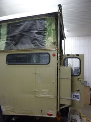
When you're preparing a vehicle for an overland expedition from Quebec to South America, reliability isn't negotiable. Marc Joinville and France Labonté of the Landtrek Adventure learned this firsthand with their 1983 Toyota Land Cruiser's pop-top camper system. The original pneumatic air ram setup worked, but air rams come with inherent limitations: they require compressed air systems, develop leaks over time, and offer minimal control over positioning. The solution? Converting to electric linear actuators that provide precise, reliable motion with the flip of a switch.
🎥 Video — Landcruiser Roof lift using 4 Tubular Linear Actuators
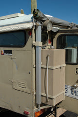
This conversion showcases an innovative application of tubular linear actuators in a fixed-shaft configuration—where the actuator body moves while the shaft remains stationary. While unconventional, this mounting approach offers distinct advantages in pop-top roof applications where vertical space is at a premium and structural mounting points dictate the installation approach. The result is a robust, weather-resistant system that has proven itself across thousands of miles of adventure travel from the Arctic to South America.
This project demonstrates the engineering versatility of modern linear actuators and provides a blueprint for anyone looking to upgrade pneumatic or manual roof lift systems on campers, trailers, or truck toppers.

The Limitations of the Original Pneumatic System
The Land Cruiser's factory pop-top system relied on a single air ram supported by four guide tubes—a common configuration in older camper designs. While functional, this setup presented several challenges for long-term expedition use:
- Air system dependency: The air ram required a working compressor and pressurized air system, adding complexity and potential failure points
- Limited control: Pneumatic systems offer minimal positioning control, typically operating in fully extended or fully retracted states
- Seal degradation: Air rams develop leaks over time, especially when exposed to temperature extremes and road vibration
- Excessive guide hardware: Four guide tubes were needed to prevent binding and maintain alignment, taking up valuable space
- Weather sensitivity: Moisture in compressed air systems can freeze in cold weather, a critical concern for Arctic travel
For an expedition vehicle traveling from Arctic Alaska to South America, these limitations represented unacceptable risks. The conversion to electric actuators eliminated the compressed air system entirely while reducing the number of guide tubes from four to two—simplifying the mechanism and improving reliability.
Understanding the Fixed-Shaft Actuator Configuration
Most linear actuator applications fix the actuator body to a stationary surface while the extending shaft creates motion. This Land Cruiser conversion demonstrates the opposite approach: the shaft end remains fixed while the actuator body slides up and down. This inverted configuration offers several advantages in pop-top applications:
Mechanical Advantages of Body-Movement Design
When the actuator body moves instead of the shaft, the force characteristics remain identical, but the mounting requirements change significantly. This approach works particularly well when:
- The fixed mounting point naturally aligns with where the shaft would terminate when fully extended
- Vertical space constraints make traditional mounting impractical
- The application benefits from the actuator body's larger surface area moving against guide structures
- Structural mounting points favor attaching the moving component to the actuator body rather than the shaft
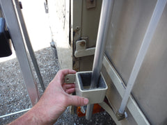
In Marc's installation, custom guide channels accommodate the actuator body's travel, maintaining alignment throughout the stroke while preventing lateral movement that could damage the internal mechanisms.
Force Distribution and Load Path
The 150-pound force rating of the actuators used in this application refers to their push/pull capacity, not the weight they're lifting. In a pop-top roof application, the actual load calculation must account for:
- The weight of the roof structure and canvas
- Wind resistance during extension and retraction
- Friction in the guide system
- Any off-axis loading from uneven terrain
- Safety margin for dynamic loads while driving
Using two 150-pound actuators provides 300 pounds of combined lifting force, which offers substantial safety margin for a pop-top roof that typically weighs 50-100 pounds. This oversizing ensures smooth operation even when the vehicle is parked on uneven ground or when one actuator encounters slightly more resistance than the other.
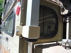
Engineering Custom Mounting Brackets and Guide System
The success of this conversion hinged on custom-fabricated mounting brackets designed specifically for the fixed-shaft configuration. Marc's bracket design demonstrates several important engineering principles for actuator installations:

Lower Bracket Design and Load Analysis
The lower brackets use a single bolt attachment—a design choice that may appear minimal but proves adequate through proper load analysis. The original pneumatic system used similarly sized fasteners, and the shear strength of a properly torqued grade 8 bolt far exceeds the forces involved. Key factors in single-bolt bracket design include:
- Shear loading: The bolt primarily experiences shear forces perpendicular to its axis, where bolts are strongest
- Bracket thickness: A thick bracket plate distributes stress across a larger bolt bearing surface
- Material selection: Steel brackets with adequate thickness prevent deformation under load
- Bolt grade and torque: Using high-grade fasteners properly torqued ensures the bracket-to-vehicle connection remains the strongest link
The redundancy of using two actuators also provides a safety factor—if one bracket were to develop issues, the second actuator maintains enough force to prevent sudden roof collapse.
Upper Bracket Integration
The upper brackets mount directly to the roof structure, securing the actuator shafts in their fixed position. This mounting approach must address:
- Waterproofing around penetrations through the roof or mounting surface
- Structural reinforcement to distribute loads across the roof framework
- Alignment precision to ensure both actuators travel parallel paths
- Accessibility for maintenance without requiring roof removal
Direct roof mounting eliminates additional linkages and pivot points, simplifying the mechanism and reducing potential failure modes.
Full-Stroke Guide System Engineering
The custom guide tubes serve multiple critical functions beyond simple alignment. Marc's full-stroke guide design provides:
- Lateral support: Prevents side-loading on the actuator rod and internal components
- Alignment maintenance: Keeps both actuators moving in parallel throughout their full stroke
- Impact protection: Guards against accidental lateral forces that could damage internal threads
- Stability insurance: Maintains system rigidity when the roof is fully extended and exposed to wind
This guide system proves especially important in expedition use, where the vehicle may be parked in wind or on uneven terrain while the roof is extended. The guides effectively turn the actuators and roof into a stable, rigid assembly rather than a mechanism dependent solely on the actuators' internal components for structural support.

Installation Process and Technical Details
Converting from pneumatic to electric actuation requires careful planning and precise execution. The installation sequence for this type of conversion typically follows these steps:
Removal and Measurement Phase
The first phase involves removing the original pneumatic system while carefully documenting mounting locations and stroke requirements. Critical measurements include:
- Total stroke length required for full roof extension
- Mounting point locations and available space
- Roof weight and center of gravity
- Clearance requirements for guide tube routing
- Electrical routing paths from vehicle battery to control box location
Actuator Selection and Specifications
The 150-pound actuators selected for this application represent a thoughtful balance of force capacity, stroke length, and physical size. When selecting actuators for similar applications, consider:
- Force rating: Calculate actual load requirements and multiply by 2-3x for safety margin
- Stroke length: Measure the required travel distance and select actuators with matching or slightly longer stroke
- Speed requirements: Faster speeds sacrifice force; roof lifts typically benefit from moderate speeds (0.5-1 inch per second)
- Environmental rating: Outdoor applications require weather-resistant or sealed actuators
- Voltage compatibility: Match actuator voltage to vehicle electrical system (typically 12V DC)
Bracket Fabrication and Mounting
Custom bracket fabrication allows precise fitment to the vehicle's specific geometry. The fabrication process includes:
- Creating cardboard templates to verify measurements and clearances
- Cutting bracket plates from appropriate thickness steel or aluminum
- Drilling mounting holes with precise spacing to match actuator end fittings
- Test-fitting brackets before final installation to verify alignment
- Applying thread locker to fasteners that will experience vibration
- Torquing all fasteners to appropriate specifications
Electrical Integration and Control
The electrical system requires proper wiring to handle the actuator current draw and provide convenient control. Essential electrical components include:
- A control box or relay system to manage actuator direction
- Appropriately sized wire gauge to handle amperage without voltage drop
- Inline fuses for overcurrent protection
- A remote control or switch panel for convenient operation
- Weather-resistant connectors for any connections exposed to elements
Running both actuators from a single control ensures synchronized movement, preventing the roof from binding or becoming misaligned during operation.
Performance in Real-World Expedition Conditions
The true test of any expedition vehicle modification comes through thousands of miles of varied terrain and climate conditions. The Landtrek Adventure's journey from Quebec to Prudhoe Bay, Alaska, and down through South America provided exactly this type of demanding real-world validation.
Temperature Extremes
Electric linear actuators handle temperature extremes far better than pneumatic systems. The Landtrek Adventure tested this across an extreme range:
- Arctic conditions: At Prudhoe Bay, temperatures well below freezing posed no issues for the electric system, while the original pneumatic system would have risked moisture freezing in air lines
- Desert heat: High temperatures through Mexico and Central America test motor windings and lubrication, but quality actuators maintain performance
- Humidity and rain: Weather-resistant actuator construction prevents moisture ingress that would corrode internal components
Vibration and Durability
Expedition driving subjects vehicles to constant vibration and occasional severe impacts from rough roads. The actuator installation proved resilient through:
- Daily operation on washboard gravel roads
- Extreme articulation on off-road trails
- Thousands of open/close cycles throughout the journey
- Exposure to dust, mud, and road grime
The guide system's role in protecting the actuators from lateral loads became especially apparent in these conditions, preventing damage that could occur from vehicle flex or uneven roof extension.
Reliability and Maintenance
Throughout the expedition, the electric actuator system required minimal maintenance—a stark contrast to pneumatic systems that need regular seal inspection and air system maintenance. The simplified electric system offered:
- No scheduled maintenance beyond occasional visual inspection
- Instant operation without waiting for air pressure buildup
- Consistent performance regardless of previous usage patterns
- Simple troubleshooting with basic electrical testing tools
Alternative Actuator Configurations for Roof Lift Applications
While the Landtrek Adventure's fixed-shaft configuration proved ideal for their specific application, other roof lift scenarios may benefit from different actuator types or mounting approaches:
Track Actuators for Guided Motion
Track actuators integrate guidance directly into the actuator assembly, eliminating the need for separate guide tubes in some applications. These units work well when:
- Mounting space allows for the wider profile of integrated tracks
- The application requires precise alignment without custom fabrication
- Lateral load protection is critical but external guides are impractical
Industrial Actuators for Heavy-Duty Applications
Larger campers or applications with heavier roofs may benefit from industrial actuators that offer:
- Higher force ratings (up to 2,200 pounds)
- More robust construction for continuous duty cycles
- Enhanced weather sealing for permanent outdoor installation
- Higher IP ratings for water and dust protection
Feedback Actuators for Precision Positioning
Applications requiring the roof to stop at intermediate positions benefit from feedback actuators that provide:
- Hall effect or potentiometer position sensing
- Precise stopping at programmable positions
- Synchronized operation monitoring to detect binding or misalignment
- Integration with more sophisticated control systems
Design Considerations for Similar Projects
Anyone planning a similar conversion from pneumatic to electric actuation should consider these key engineering factors:
Proper Load Calculation
Accurately measuring or calculating the actual weight and forces involved prevents under-sizing actuators. Consider:
- Static weight of the roof assembly
- Dynamic loads from wind resistance during operation
- Friction in guides and pivot points
- Safety margin for off-axis loading on uneven terrain
- Future modifications that might add weight
Synchronization Strategy
Using multiple actuators requires keeping them synchronized to prevent binding. Options include:
- Parallel wiring: Simplest approach where identical actuators receive identical power, relying on mechanical resistance to equalize
- Feedback control: Using feedback actuators with Arduino or similar controller to monitor and adjust each actuator independently
- Mechanical linking: Connecting actuators through synchronization cables or gears (adds complexity)
Environmental Protection
Outdoor vehicle applications demand attention to weather protection:
- Seal all electrical connections with heat-shrink tubing or weather-resistant connectors
- Route wiring away from heat sources and sharp edges
- Use cable grommets where wires pass through metal panels
- Apply dielectric grease to connections exposed to moisture
- Consider actuator boots or bellows for added protection in extremely dusty environments
Emergency Operation Planning
Any motorized roof system should include provisions for manual operation in case of electrical failure:
- Design the system so the roof can be manually pushed closed if needed
- Consider including a manual crank backup for emergency actuation
- Ensure the roof can be safely secured in the closed position even with actuator failure
- Keep spare fuses and basic electrical troubleshooting tools accessible
Cost-Benefit Analysis: Electric vs. Pneumatic
Converting from pneumatic to electric actuation represents an investment in reliability and simplicity. The cost comparison includes:
Initial Investment
- Electric system: Actuators, control system, wiring, and brackets typically range from $300-600 depending on force requirements and control sophistication
- Pneumatic system: Comparable pneumatic system requires air ram, compressor (if not present), pressure switches, air lines, and fittings for similar cost
Long-Term Ownership Costs
- Electric advantages: No seal replacement, no compressor maintenance, no air system leak repairs
- Pneumatic disadvantages: Regular seal service, air system troubleshooting, compressor replacement, moisture management
Operational Benefits
- Instant operation without air pressure buildup
- Silent operation compared to compressor noise
- No energy waste from air system leaks
- Precise control and intermediate positioning capability
- Reduced system complexity and failure points
Conclusion
The Landtrek Adventure's conversion from pneumatic to electric roof actuation demonstrates how modern linear actuators can dramatically improve reliability and usability in expedition vehicle applications. By thoughtfully engineering custom mounting brackets and guide systems, Marc and France created a robust solution that has proven itself across thousands of miles through extreme conditions from the Arctic to South America.
The innovative fixed-shaft configuration showcases the versatility of electric linear actuators—they don't always need to be used in conventional mounting orientations to be effective. By understanding the forces involved, properly sizing components, and designing adequate support structures, DIY builders and professional fabricators alike can adapt these reliable actuators to almost any motion control challenge.
For anyone planning a similar pop-top roof conversion or other vehicle automation project, this case study provides a proven blueprint. The principles of proper load calculation, synchronized operation, environmental protection, and robust mounting apply across a wide range of applications beyond camper roofs—from tonneau covers to cargo doors to specialty access panels.
Frequently Asked Questions
What stroke length do I need for a pop-top camper roof?
Most pop-top camper roofs require 10-18 inches of stroke length, depending on the specific design. Measure the vertical travel distance from fully closed to fully extended, then select actuators with stroke length equal to or slightly exceeding this measurement. It's better to have slightly more stroke than needed, as you can limit travel electronically or mechanically, but you cannot extend an actuator beyond its maximum stroke. The Landtrek Adventure likely used actuators in the 12-16 inch stroke range based on typical Land Cruiser camper configurations.
How much force do I need to lift my camper roof?
Calculate the total weight of your roof assembly, then multiply by 2-3 for a safety margin. A typical pop-top camper roof weighs 50-100 pounds. Using two 150-pound actuators (300 pounds combined) provides substantial margin for friction, wind resistance, and off-axis loading. If your roof is heavier or includes solar panels or additional equipment, consider higher force ratings. Remember that force requirements also depend on mounting geometry—actuators mounted at an angle require higher force ratings than vertical installations.
Will two actuators stay synchronized without special controls?
When identical actuators are wired in parallel to the same power source, they naturally tend to synchronize due to mechanical resistance. If one actuator gets ahead, it encounters more resistance (from the tilting roof), which causes it to draw more current and slow down while the other catches up. However, this passive synchronization works best when actuators are properly guided to prevent binding. For applications requiring precise position control, feedback actuators with electronic control provide more reliable synchronization. The Landtrek installation's guide system helps ensure both actuators follow parallel paths, supporting passive synchronization.
Do linear actuators need special protection for outdoor vehicle use?
Quality linear actuators designed for outdoor use typically have IP65 or IP66 ratings, providing protection against dust and water spray. This is generally sufficient for vehicle applications where the actuators are somewhat protected by the camper structure. For maximum protection in extremely harsh conditions, consider adding protective boots around the shaft, applying dielectric grease to electrical connections, and ensuring all wiring uses weather-resistant connectors. The Landtrek Adventure's system has proven durable across extreme temperatures from Arctic to tropical conditions without additional weatherproofing beyond standard actuator construction.
Can I manually open the roof if the actuators fail?
Most electric actuator installations can be designed to allow manual operation in emergencies. The actuators contain a gear reduction mechanism that normally prevents back-driving (the roof won't fall if power is lost), but this also means you cannot easily push the actuators by hand. For emergency manual operation, you can either: 1) Disconnect the actuators and manually lift the roof with temporary supports, 2) Install a manual override mechanism like a hand crank that engages the actuator gear train, or 3) Carry spare fuses and basic electrical troubleshooting tools to restore power in the field. The Landtrek Adventure's guide system also provides structural support that would help secure the roof in an emergency situation.
How much power do roof lift actuators consume?
Typical 12V DC actuators in the 150-pound force range draw 3-6 amps during operation, depending on load and speed. Two actuators operating simultaneously would draw 6-12 amps total. A complete roof lift cycle (open or close) typically takes 20-40 seconds, so the total energy consumption is minimal—roughly equivalent to running your vehicle's headlights for half a minute. This low power consumption makes electric actuators ideal for vehicle applications where battery capacity is limited. The system can operate multiple times per day without significantly impacting your vehicle's battery, though it's generally wise to run the engine or have a power supply connected during operation to avoid draining the battery.
Can I adjust the speed of the actuators?
The speed of a standard DC linear actuator is determined by its internal gear ratio and motor design, and cannot be easily adjusted once manufactured. However, you can control speed through the input voltage—reducing voltage slows the actuator but also reduces available force. For applications requiring variable speed control, consider using a PWM (pulse width modulation) motor controller, though this adds complexity. Most roof lift applications work well with the fixed speed of standard actuators (typically 0.5-1.0 inches per second), as this provides a good balance of reasonable operation time without excessive force loss.


