If you pick RC values that don’t fit your actual timing or filtering need, the result is simple: your delay is off, your frequency cutoff isn’t where you think, or the circuit might even start to oscillate when you don’t want it to. This RC Circuit Calculator lets you quickly work out time constants, capacitor voltages during charging/discharging, cutoff frequency, AC impedance, phase angle, and stored energy for any combination of R and C you need. You’ll find RC circuits everywhere: audio or RF filters, delay circuits in cars and industry, or just decoupling to tame supply noise on a board. Below you’ll find core equations, a real automotive relay example, a quick how-to use case, and a detailed FAQ.
What is an RC circuit?
An RC circuit is just a resistor and capacitor wired together, usually in series or sometimes parallel. That’s it. By picking R and C, you set a predictable time delay (how fast things charge/discharge) or set what frequencies the circuit lets through or blocks — basic and practical, but everywhere in real electrical design.
Simple Explanation
Picture a bucket (capacitor) being filled by a narrow pipe (resistor). Make the pipe narrower (larger R) or the bucket bigger (larger C), and it simply takes longer to fill. That’s your RC time constant: it’s the direct throttle on how quickly your circuit responds when the voltage changes suddenly.
📐 Browse all 1000+ Interactive Calculators
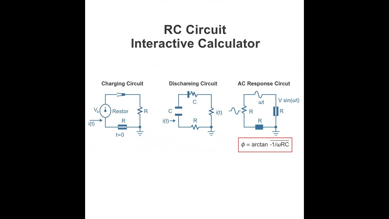
RC Circuit Diagram

How to Use This Calculator
- Pick the calculation mode: time constant, voltage at a certain point, frequency, impedance, phase, energy, or time for a chosen percentage.
- Enter R (ohms) and C (farads). You’ll get extra fields for voltage, time, frequency, etc. as needed by the mode you’ve chosen.
- Fill out the required inputs according to your circuit.
- Hit Calculate and check your answer — adjust as needed for your real use case.
RC Circuit Interactive Calculator
This calculator is intended for education, concept evaluation, and preliminary design. Results are based on the equations and assumptions described on this page, but cannot account for every real-world load case, tolerance, material property, environmental condition, installation detail, safety factor, code, or regulatory requirement. Verify all inputs, assumptions, units, and results independently before selecting components or using the result in a real application. Safety-critical, structural, medical, lifting, transportation, or regulated applications must be reviewed by a qualified engineer.
Questions about this calculator or found an error? Message our engineering team.
RC Circuit Interactive Visualizer
You can see in real time how changing R and C affects things like the charge curve and cutoff frequency. Move the slider and watch the exponential charge shape and where the filter starts rolling off.
TIME CONSTANT
0.10 s
CUTOFF FREQ
1.6 Hz
FINAL VOLTAGE
7.6 V
FIRGELLI Automations — Interactive Engineering Calculators
RC Circuit Equations
Simple Example
R = 10,000 Ω, C = 0.000001 F (1 µF), V₀ = 12 V, t = 0.01 s
Time constant: τ = 10,000 × 0.000001 = 0.01 s
Charging voltage at t = 0.01 s: VC = 12 × (1 − e−1) = 12 × 0.632 = 7.58 V
Cutoff frequency: fc = 1 / (2π × 0.01) ≈ 15.92 Hz
Time Constant
Use the formula below to calculate the RC time constant.
τ = R × C
where: τ = time constant (s), R = resistance (Ω), C = capacitance (F)
Charging Voltage (Capacitor)
Use the formula below to calculate charging voltage.
VC(t) = V₀ × (1 − e−t/τ)
where: VC = capacitor voltage at time t (V), V₀ = source voltage (V), e = Euler's number (≈2.718)
Discharging Voltage (Capacitor)
Use the formula below to calculate discharging voltage.
VC(t) = V₀ × e−t/τ
where: V₀ = initial capacitor voltage (V)
Charging Current
Use the formula below to calculate charging current.
i(t) = (V₀ / R) × e−t/τ
where: i = current through circuit (A)
Cutoff Frequency (Low-Pass Filter)
Use the formula below to calculate cutoff frequency.
fc = 1 / (2πτ) = 1 / (2πRC)
where: fc = cutoff frequency (Hz), π ≈ 3.14159
Capacitive Reactance (AC)
Use the formula below to calculate capacitive reactance.
XC = 1 / (ωC) = 1 / (2πfC)
where: XC = capacitive reactance (Ω), ω = angular frequency (rad/s), f = frequency (Hz)
Total Impedance (AC)
Use the formula below to calculate total AC impedance.
Z = √(R² + XC²)
where: Z = total impedance magnitude (Ω)
Phase Angle (AC)
Use the formula below to calculate phase angle.
φ = arctan(−XC / R)
where: φ = phase angle (radians or degrees), negative indicates current leads voltage
Energy Stored in Capacitor
Use the formula below to calculate energy stored in a capacitor.
E = ½ × C × V²
where: E = energy stored (J), V = voltage across capacitor (V)
Theory & Practical Applications
RC Circuit Fundamentals and Dynamic Behavior
RC circuits are as basic as you get — just a resistor and a capacitor — but they run half of practical electronics, from timings and filters to various signal tweaks. The time constant τ = RC sets how quickly everything happens. In a straight resistor circuit, you get instant changes when you flip the voltage; drop in a capacitor, and now voltage or current change is smoothed out, following an exponential curve. The time constant isn’t some mysterious figure — it simply tells you how fast things get close to the new value. After one τ the charge curve has hit about 63%; after 5τ you’re almost at the final value (over 99%), which, for most jobs, is as “finished” as it needs to get in the real world.
The underlying math comes from Kirchhoff’s law plus how capacitors work: Q = CV, so current i = C(dV/dt). At turn-on, the whole supply tries to push current through the resistor, because the cap starts at 0V. As the capacitor charges, its voltage rises, so there’s less push across the resistor, and current drops off exponentially. This is what keeps current surges in check — the resistor gives you a natural soft start, protecting sensitive stuff from getting fried with a sudden inrush.
Timing Applications and Precision Considerations
Most simple delay circuits use nothing but an RC. They set off blinkers, make wipers pause, let relays stay energized after power-off, and run basic time delays in machinery. When you need real accuracy, though, you have to deal with component tolerances: if your resistor is ±5% and your capacitor ±10%, the total error can be up to 15% worst-case (in practice, the error is a little better statistically). Temperature matters too: electrolytic caps can drift between −2% and +20% depending on the temperature, while film types are far more stable. If you want your timing to stay within ±5%, stick to 1% metal film resistors and decent film capacitors, not cheap electrolytics.
One practical catch: actual capacitors always leak a bit, so they self-discharge over time. This is called leakage resistance, and it acts like another resistor in parallel with your main resistor. If you stick to moderate resistor values, leakage isn’t much of an issue, but if you try to get long delays by using megaohm resistors, leakage can dominate and your actual delay is less than expected. For large delays (over several minutes), RC is a poor solution compared to a proper timer chip or digital counter.
Frequency Response and Filter Applications
Feed an RC with an AC signal and it becomes a filter — the classic “frequency-dependent voltage divider.” The cutoff frequency (fc = 1/(2πRC)) is where you get −3 dB, or the signal’s power is halved. Below cutoff, the capacitor acts like an open (high impedance), above cutoff like a short. That’s your basic low-pass filter, attenuating by −20 dB/decade after cutoff. Nothing fancy — just pick R and C, and you know exactly where your filter starts to take effect. Multiple RCs in a row will steepen the slope, though then you start to care about loading and phase shift stacking up.
RC phase shift is a fact of life in AC: the circuit always shifts voltage and current out of alignment by a few degrees, from 0° at DC to −90° at high frequency. At the cutoff frequency, you’ve got a −45° phase shift. Stack up a few RC stages and you can run into phase issues, enough to destabilize feedback amplifiers if you haven’t planned for it. Always check your amplifier’s phase margin if you’re using RC compensation.
Signal Conditioning and Practical Circuit Design
RCs show up in real circuits for both blocking (DC decoupling) and bypassing (AC shunting). For example, to avoid losing low frequencies in audio coupling, make sure your cap is big enough that its reactance at the lowest frequency of interest is below about a tenth of your input impedance. That way, you get less than 0.5% amplitude loss. In power supplies, small ceramic capacitors (0.1 µF) close to the IC pins kill RF noise, while big electrolytics (10–100 µF) damp slower supply changes. If you use capacitors with high ESR (series resistance), your “RC” filter might stop working as a filter above a few kHz.
For supply decoupling in modern circuits, lead lengths are worth checking — a few millimeters extra can kill your high-frequency performance, especially above 10 MHz. That’s why you’ll see surface-mount ceramics packed right against ICs, not left floating on long traces. If you need to filter high-frequency noise in switching supplies, low-ESR polymer or ceramic capacitors are the only practical choices.
Worked Example: Automotive Relay Delay Circuit Design
Problem: Want to keep a car’s dome light on for 18 seconds after closing the door? Here’s what you know: the relay coil pulls 85 mA at 12 V (so resistance is 141 Ω) and disconnects if the current drops below 50 mA. The car’s system can get as high as 15.7 V and as low as 12.7 V. Work out R, C values; delays for best/worst supply voltage; resistor dissipation; and pick a safe capacitor voltage rating.
Solution:
(a) Component Selection: The relay drops out at 7.05 V (0.050 A × 141 Ω). You need the capacitor to discharge from the highest supply voltage down to 7.05 V in 18 seconds. Using the discharge formula, that works out to a τ (time constant) of about 25.75 seconds. Pick a common cap — say 2200 µF (0.0022 F) — now solve for R:
τ = R × C
25.75 = R × 0.0022
R = 11,705 Ω
12 kΩ is the nearest standard value, so τ becomes 26.4 s. Plugging that in gives you about 18.45 seconds of actual delay at nominal voltage. The math looks good — you’ve landed close enough for most practical automotive needs.
(b) Delay Variation with Supply Voltage: Drop the voltage, and delay shortens (to 15.6 s at 12.7 V). Raise the voltage, and delay stretches (to 21.2 s at 15.7 V). You get a ±18% swing, which is about what you can expect for a basic RC delay in a car environment — not precision, but fine for non-critical uses.
(c) Power Dissipation: The initial surge is the worst case: about 17–21 mW depending on voltage — less than 1/10 of a 1/4 watt resistor’s limit. Even after the relay’s pulled in, almost all steady current goes straight through the relay coil, not the resistor, so resistor heating isn’t an issue here.
(d) Capacitor Voltage Rating: Cap charges up to the highest voltage in the system during use — call it 15.7 V worst case. Automotive systems spike even higher during alternator load dump, so while 25 V is the bare minimum, 35 V or 50 V is smart. Size for the real abuses your circuit will see, not just the normal number. For this design: 2200 µF/35 V electrolytic is a good starting point, with a 12 kΩ, 1/4 W resistor. That gets you a delay of roughly 15–21 seconds with realistic tolerance swings.
Energy Storage and Power Delivery Considerations
RC circuits store a modest amount of energy in the cap (E = ½CV²). In the example above, a 2200 µF cap juiced up to 14.2 V holds about 0.22 J. Spreading that over an 18 second delay, the average output is only about 12 mW. For short, high-power bursts (like a camera flash), you can charge a big capacitor and dump it in a millisecond, but then you have to size the charging resistor so you don’t blow out your supply or the cap itself. Charge is still exponential — most of the charging happens within 3–5τ, then it’s close enough to “full” to trigger most circuits.
For more calculators and reference tools, the FIRGELLI Engineering Calculator Hub collects them all in one practical spot.
Frequently Asked Questions
Free Engineering Calculators
Explore our complete library of free engineering and physics calculators.
Browse All Calculators →🔗 Explore More Free Engineering Calculators
- I2C/SPI Bus Speed & Pull-up Resistor Sizing
- Capacitor Charge Discharge Calculator — RC Circuit
- I2C Pull-Up Resistor Calculator
- LED Resistor Calculator — Current Limiting
- Delta To Wye Calculator
- Noise Figure Calculator
- Inductor Energy Calculator
- Ohm's Law Calculator — V I R P
- Voltage Divider Calculator
- Transformer Turns Ratio Calculator
About the Author
Robbie Dickson — Chief Engineer & Founder, FIRGELLI Automations
Robbie Dickson brings over two decades of engineering expertise to FIRGELLI Automations. With a distinguished career at Rolls-Royce, BMW, and Ford, he has deep expertise in mechanical systems, actuator technology, and precision engineering.
Video Walkthrough - How to Use This Calculator
Need to implement these calculations?
Explore the precision-engineered motion control solutions used by top engineers.


