Controlling Linear Actuator Speed with Arduino and Motor Drivers
Precise speed control is essential for countless automation projects, from adjustable workstations to robotics and custom machinery. While linear actuators provide the mechanical motion, controlling their speed smoothly and reliably requires proper electronics. The Arduino platform, combined with an appropriate motor driver, offers an accessible yet powerful solution for both hobbyists and professional engineers developing custom motion control systems.
This comprehensive tutorial demonstrates how to implement variable speed control for DC linear actuators using Arduino microcontrollers and motor driver circuits. We'll cover both fixed-speed and variable-speed implementations, explaining the underlying principles of PWM (pulse width modulation) control, current requirements, and best practices for reliable operation. Whether you're building a one-off prototype or developing a production system, understanding these fundamental concepts will enable you to create sophisticated motion control solutions.
Important Note: This tutorial assumes working knowledge of basic electronics principles, Arduino hardware, and Arduino IDE software. If you're new to Arduino, we recommend starting with beginner tutorials widely available through Arduino's official documentation and community resources. Please be aware that FIRGELLI Automations does not provide technical support for custom applications or debugging assistance beyond these publicly available tutorials.
Required Components and Tools
Before beginning this project, gather the following components and tools:
- 12V Linear Actuator: Any DC linear actuator rated for 12V operation. Current draw typically ranges from 2-5A depending on load conditions.
- 12V Power Supply: Must provide sufficient current for your actuator under load. A power supply rated for at least 5A is recommended for most standard actuators.
- Arduino Board: Arduino Uno, Mega, or compatible microcontroller. This tutorial uses the Uno's pin layout as reference.
- Motor Driver Module: An H-bridge motor driver capable of handling your actuator's current requirements. Popular options include the L298N, IBT-2, or similar modules rated for 5A or higher.
- Potentiometer (Optional): 10kΩ linear taper potentiometer for variable speed control implementation.
- Connecting Wires: Appropriate gauge wire for power connections (18-22 AWG recommended) and jumper wires for signal connections.
- Crimping Tool or Soldering Iron: For making secure electrical connections.
Understanding Current Requirements and Motor Drivers
The DC motors inside linear actuators draw significantly higher current than Arduino's digital pins can safely provide. Arduino digital pins are rated for only 40mA maximum current, while linear actuators typically require 2-5A during operation, with peak currents potentially reaching 8-10A during startup or stall conditions.
Connecting an actuator directly to Arduino pins would immediately damage the microcontroller. This is where motor drivers become essential. A motor driver acts as an electronic switch, accepting low-current control signals from the Arduino (typically under 20mA) and switching high-current power from an external supply to the motor. This electrical isolation protects the Arduino while enabling control of powerful motors.
Motor drivers use H-bridge circuits to control both direction and speed. An H-bridge contains four switching elements (transistors or MOSFETs) arranged to allow current flow in either direction through the motor. By controlling which switches are active, we can make the motor spin forward, reverse, or stop. The motor driver interprets the PWM signals from Arduino and translates them into appropriate switching patterns for the H-bridge.
Selecting the Right Motor Driver
When choosing a motor driver for your application, consider these critical specifications:
- Continuous Current Rating: Must exceed your actuator's typical operating current with at least 20% margin for safety.
- Peak Current Rating: Should handle startup surge currents, typically 1.5-2x the continuous rating.
- Voltage Rating: Must match your actuator's voltage (12V, 24V, etc.) with adequate overhead.
- Logic Level Compatibility: Should accept 5V logic signals from Arduino without level shifting.
- Thermal Management: Adequate heatsinking for your application's duty cycle.
Fixed Speed Control Implementation
The basic implementation provides programmatic control over actuator speed and direction. This configuration is ideal for applications requiring preset speeds or simple automated sequences.
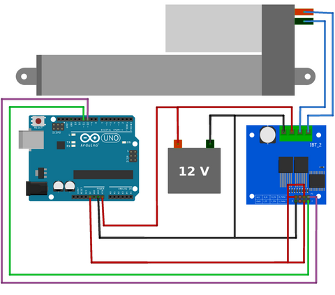
Wiring Connections
Connect the motor driver to your Arduino using two PWM-capable digital pins. On the Arduino Uno, pins 10 and 11 are used in this example, though any PWM pins (marked with ~ on the board) will work. The motor driver's power inputs connect to your 12V supply, while the motor outputs connect to the actuator's two motor wires. Ensure proper polarity for the power supply and verify all ground connections are common between the Arduino, motor driver, and power supply.
Code Explanation and Operation
The control logic operates on simple principles. By setting one PWM pin HIGH and the other LOW, current flows through the motor in one direction, extending the actuator. Reversing the pin states reverses the current flow, retracting the actuator. Setting both pins LOW stops current flow, halting motion. The PWM duty cycle (controlled by the Speed variable ranging from 0-255) determines motor voltage and thus speed.
Here's the complete code for fixed-speed control:
Code: View on GitHub
Understanding PWM Speed Control
PWM operates by rapidly switching the motor power on and off. The duty cycle—the percentage of time the signal is HIGH versus LOW—determines the average voltage delivered to the motor. A 50% duty cycle delivers half the supply voltage on average; 75% delivers three-quarters voltage, and so on. Linear actuators respond to this average voltage by adjusting their speed proportionally.
The Arduino's analogWrite() function generates PWM signals automatically. The value you provide (0-255) sets the duty cycle: 0 is always off (0% duty cycle), 255 is always on (100% duty cycle), and 127 is approximately 50% duty cycle. This gives you 256 discrete speed settings for precise control.
Variable Speed Control with Potentiometer
For applications requiring real-time speed adjustment—such as manual workstation controls or user interfaces—integrating a potentiometer provides intuitive analog control over actuator speed and direction.
Potentiometer Operation and Voltage Division
A potentiometer is a three-terminal variable resistor that functions as a voltage divider. By connecting the two outer terminals to 5V and ground (GND), and the center wiper terminal to an Arduino analog input, rotating the shaft varies the output voltage from 0V to 5V. The Arduino's analog-to-digital converter (ADC) reads this voltage and converts it to a digital value ranging from 0 to 1023, providing fine-grained position sensing.
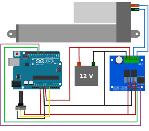
Wiring the Potentiometer
Connect one outer terminal of the potentiometer to the Arduino's 5V pin, the opposite outer terminal to GND, and the center wiper terminal to analog input A0. The order of the 5V and GND connections determines the direction of control—if rotating clockwise decreases the reading when you expect it to increase, simply swap the 5V and GND connections.
Code Explanation: Bidirectional Control
This implementation divides the potentiometer's range into two zones. Readings from 512-1023 (center to one end) command extension, with speed increasing as you rotate further from center. Readings from 0-511 (center to opposite end) command retraction, with speed similarly increasing. At the center position (around 512), the actuator stops. This provides intuitive control where neutral position means stopped, and rotation in either direction provides proportional speed in that direction.
The map() function performs the critical conversion from analog readings to PWM values. For the extension zone (512-1023), we map this range to PWM values 0-255. For the retraction zone (0-511), we similarly map to 0-255 but reverse the motor direction by swapping which pin is HIGH and which is LOW.
Code: View on GitHub
Advanced Considerations and Optimization
Implementing Dead Zones
In practical applications, you may want to implement a "dead zone" around the center position to prevent unwanted motion from minor potentiometer jitter or drift. This can be accomplished by modifying the if/else conditions to ignore readings between, for example, 490-534. Within this range, both motor pins would be set LOW, ensuring the actuator remains stationary until deliberate input is provided.
Current Sensing and Protection
Professional applications often benefit from current monitoring. Many motor drivers include current sense outputs that provide a voltage proportional to motor current. By reading this with an Arduino analog input, you can detect stall conditions, implement soft-start routines, or trigger protective shutdowns if current exceeds safe thresholds. This is particularly valuable when using industrial actuators in demanding applications.
Acceleration and Deceleration Profiles
Rather than instantly changing speed when the potentiometer moves, implementing gradual acceleration and deceleration creates smoother motion and reduces mechanical stress. This can be achieved by reading the target speed from the potentiometer but adjusting the actual PWM output incrementally over time using a simple state machine or acceleration curve algorithm.
Position Feedback Integration
For applications requiring precise positioning, consider using feedback actuators that include built-in potentiometric or hall-effect position sensors. By reading the feedback signal on another Arduino analog input, you can implement closed-loop position control, automatically adjusting speed based on the difference between current and target positions.
Troubleshooting Common Issues
Actuator Not Moving
If your actuator doesn't move, first verify power supply connections and measure voltage at the motor driver's power input terminals with a multimeter. Confirm the Arduino is outputting PWM signals by uploading a simple LED blink sketch to the same pins. Check that all grounds are properly connected—Arduino ground, motor driver ground, and power supply ground must share a common connection.
Erratic or Inconsistent Behavior
Electrical noise from the motor can interfere with Arduino operation. Install a 0.1µF ceramic capacitor between each motor terminal and ground, directly at the actuator. These suppression capacitors filter high-frequency noise. Additionally, ensure power supply wiring uses adequate wire gauge (18-22 AWG for 12V/5A applications) and keep motor power wiring separate from Arduino signal wiring where possible.
Motor Driver Overheating
If the motor driver becomes excessively hot, it may be undersized for your actuator or experiencing poor thermal management. Verify the driver's continuous current rating exceeds your actuator's typical draw. Ensure any heatsinks are properly installed with thermal compound. Consider adding a cooling fan for continuous-duty applications or reducing the duty cycle to allow cooling periods.
Practical Applications and Project Ideas
This speed control technique enables numerous automation projects. Adjustable standing desk systems benefit from variable speed control for smooth, quiet height adjustment. Custom TV lift mechanisms can provide graceful motion with acceleration and deceleration. Robotic projects use this control method for proportional joint movement. Agricultural automation, solar panel trackers, and automated window or vent systems all rely on these same fundamental principles.
For projects requiring multiple actuators, the same Arduino can control several motor drivers simultaneously by using additional PWM pin pairs. Synchronized motion of multiple linear actuators enables complex mechanisms like coordinated lifting tables or multi-axis positioning systems.
Conclusion
Arduino-based speed control for linear actuators provides an accessible entry point into motion control while offering enough flexibility for sophisticated applications. By understanding PWM principles, current requirements, and proper motor driver implementation, you can create reliable automation systems tailored to your specific needs. Whether implementing fixed preset speeds or continuous variable control via potentiometer, these techniques form the foundation for countless automation projects.
As you develop your skills, consider exploring more advanced topics like closed-loop position control with feedback actuators, multi-actuator synchronization, or integration with wireless control systems. The principles covered here scale from simple hobby projects to industrial automation systems, making Arduino an invaluable tool in modern motion control development.
Frequently Asked Questions
Why can't I connect the linear actuator directly to Arduino pins?
Arduino digital pins are rated for only 40mA maximum current, while linear actuators typically draw 2-5A during operation and can peak at 8-10A during startup. Connecting an actuator directly would immediately damage the Arduino's output pins and potentially destroy the microcontroller. Motor drivers provide the necessary current amplification, accepting low-current signals from Arduino and switching high-current power from an external supply to the actuator safely.
Do I need to use specific Arduino pins for motor control?
Yes, you must use PWM-capable pins for speed control. On the Arduino Uno, these are pins 3, 5, 6, 9, 10, and 11 (marked with ~ on the board). While you can use any two PWM pins for basic motor control, some pins share timers which may cause interference with certain libraries. Pins 9 and 10 share a timer, as do pins 3 and 11, so using one pin from each pair (like 10 and 11 as shown in this tutorial) avoids potential conflicts.
What size power supply do I need for my linear actuator?
Your power supply must provide sufficient voltage (typically 12V or 24V to match your actuator) and current capacity exceeding your actuator's peak draw. Most standard 12V actuators draw 3-5A under load, but can surge to 8-10A during startup or stall conditions. A power supply rated for at least 5-6A provides adequate headroom for reliable operation. Always check your specific actuator's specifications and add 20-30% margin for safety.
Can I control multiple linear actuators with one Arduino?
Yes, a single Arduino can control multiple actuators by using additional motor drivers and PWM pin pairs. An Arduino Uno has six PWM pins, allowing control of up to three actuators independently (using two pins per actuator). For larger systems requiring four or more actuators, consider using an Arduino Mega which provides 15 PWM pins. Each actuator needs its own motor driver, but they can share the same power supply if it has sufficient current capacity for all actuators combined.
Why doesn't my actuator move at low PWM values?
All DC motors have a minimum voltage threshold below which they cannot overcome static friction and internal resistance to begin moving. For most linear actuators, this threshold corresponds to PWM values roughly between 40-80 (out of 255). Below this point, the average voltage is insufficient to energize the motor. You can address this by mapping your speed values to a restricted range (for example, mapping 0-255 to 80-255) ensuring even your minimum speed command provides enough voltage for reliable motion.
How do I implement position control instead of just speed control?
Position control requires feedback actuators that include built-in position sensors (typically potentiometric or hall-effect sensors). Connect the feedback signal to an Arduino analog input to read current position. Implement a control loop that compares current position to target position, adjusting speed based on the error. Simple proportional control sets speed proportional to position error—large errors command high speed, small errors command slow speed, creating smooth approach to target positions. This forms the basis of PID (Proportional-Integral-Derivative) control used in professional motion control systems.


