Building a Hidden TV System with TiVo Remote Control and Arduino
Hidden TV installations have become increasingly popular in modern home design, offering an elegant solution that transforms entertainment spaces while preserving aesthetic appeal. Whether concealing a television behind artwork, within cabinetry, or integrated into architectural features, these systems require reliable motion control that can be operated seamlessly. This project demonstrates how to create a sophisticated hidden TV system using a TiVo remote control, Arduino microcontroller, and a track actuator from FIRGELLI Automations to lift a painting that covers your television.
🎥 Video — TiVo Remote Controlled Linear Actuator
What makes this project particularly valuable is its integration with existing home entertainment equipment. Rather than adding yet another remote control to your collection, this solution leverages the TiVo remote you already use daily. The system responds to the thumbs up and thumbs down buttons, making operation intuitive and eliminating the need for dedicated control hardware. This approach represents the intersection of home automation, custom electronics, and practical engineering—demonstrating how linear actuators can be integrated into sophisticated control systems.
The complete build process outlined below takes you through every step, from initial component selection through final assembly and testing. While this guide assumes basic familiarity with electronics and soldering, the instructions are detailed enough for enthusiastic DIYers to complete successfully. The video demonstration at the end of this article provides visual confirmation of the finished system in operation.
Required Tools and Equipment
Before beginning this project, gather the following tools. Having everything prepared in advance will make the build process more efficient and reduce the likelihood of project delays.
- #0 Phillips screwdriver for working with small electronics and terminal blocks
- Soldering iron with temperature control (recommended for precision work)
- Electronic solder (60/40 rosin core recommended)
- Wire cutters with precision cutting edges
- Small pliers designed for electronics work (needle-nose or specialized)
- Wire strippers for 18-22 AWG wire
- Digital multimeter for testing continuity (optional but recommended)
Complete Parts List and Component Selection
This project requires specific components to function correctly. The parts list below includes manufacturer information where relevant to ensure compatibility. Note that while some substitutions are possible, the relay module and infrared receiver specifications are critical for proper operation.
Core Motion Control Components
- Heavy Duty Track Actuator from FIRGELLI Automations: Select the stroke length based on your specific installation requirements. Track actuators provide exceptional side-load capacity and stability, making them ideal for lifting artwork or panels mounted perpendicular to the actuator shaft.
- TiVo Roamio Remote Control: The infrared codes from this remote are programmed into the Arduino sketch. Other TiVo models may work but will require code modification.
Electronics and Control Components
- Arduino Uno Rev 3: The microcontroller platform that processes infrared signals and controls the relay module
- Hammond 1591ESBK ABS Project Box Black (7.5" x 4.3" x 2.2"): Houses the completed circuit and provides protection for the electronics
- Microtivity IB171 170-point Mini Breadboard for Arduino: Facilitates connection distribution and testing
- Infrared Receiver (2.5–5.5V, 38kHz): Receives and decodes signals from the TiVo remote. The 38kHz frequency specification is essential for compatibility with consumer IR remotes.
- SainSmart 2-Channel Relay Module: Provides the electrical switching necessary to reverse polarity and control actuator direction
- 100PCS Michael Josh 20CM M/F Jumper Wires (1 Pin Plug Male to Female): Connects components on the breadboard and between modules
- USB 2.0 Cable (A-Male to B-Male): Programs the Arduino and can provide power during operation
- 4 feet of 18/5 Black Sprinkler Wire: Multi-conductor cable used for connecting the infrared sensor to the control circuit
Mounting Hardware
- 8 qty #4–40 x 2" stainless steel machine screws
- 8 qty #4–40 machine screw nuts
- 16 qty ½" nylon spacers
- 1 qty cable zip tie for strain relief
Arduino Configuration and Pin Assignment
The Arduino Uno serves as the brain of this automation system, receiving infrared signals and controlling the relay module that switches actuator polarity. Understanding the pin configuration is essential for successful assembly and troubleshooting.
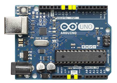
The following Arduino pins are utilized in this project:
- Power 5V: Provides regulated 5-volt power to the infrared receiver and relay module VCC
- Digital Pin #8: Controls the first relay channel (actuator extension)
- Digital Pin #9: Controls the second relay channel (actuator retraction)
- Digital Pin #11: Receives decoded infrared signals from the IR receiver
- Power GND: Common ground reference for all components
The Arduino's regulated power output is sufficient for the low-current control circuit, but the linear actuator itself requires connection to its dedicated power supply. The relay module performs galvanic isolation between the low-voltage control circuit and the actuator power circuit.
Relay Module Setup and Jumper Configuration
The SainSmart 2-channel relay module requires specific jumper configuration to create an H-bridge circuit capable of reversing polarity to the actuator. This configuration enables bidirectional control—essential for extending and retracting the actuator shaft.
Initial Relay Configuration
The relay module arrives with a blue jumper connecting JD-VCC to VCC. Leave this jumper in place—it allows the relay coils to be powered from the same 5V source as the logic circuits. Removing this jumper would require a separate power supply for the relay coils.
Creating the H-Bridge Connections
To enable polarity reversal, you must jumper specific terminals on the relay board:
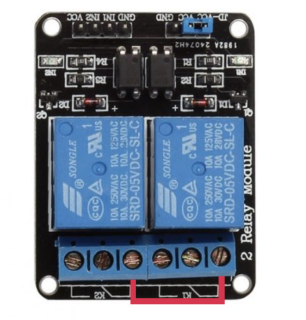
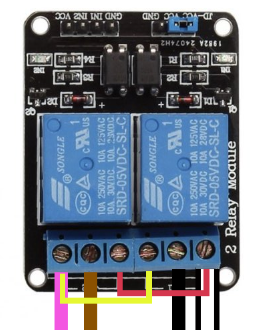
First jumper connection: Connect K1 position 1 to K2 position 1 using a jumper wire. This connection creates one side of the H-bridge circuit. In the reference image, this jumper is shown in red.
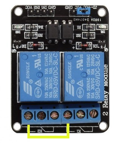
Second jumper connection: Connect K1 position 3 to K2 position 3 using a second jumper wire. This completes the opposite side of the H-bridge. In the reference image, this jumper appears in yellow.
When properly configured, activating relay K1 closes one circuit path while K2 remains open, causing current to flow through the actuator in one direction. Activating K2 instead reverses the current flow. Both relays should never be activated simultaneously, as this would create a short circuit—the Arduino code prevents this condition.
Infrared Sensor Wiring and Connection
The infrared receiver is the system's input device, decoding the 38kHz modulated signals from the TiVo remote and converting them to digital data the Arduino can process. Proper wiring is critical for reliable operation.
Preparing the Wire
The 18/5 sprinkler wire contains five conductors, but only three are needed for this application. Strip back approximately two inches of the outer jacket to expose the individual conductors. Identify the green, white, and blue wires—these will connect to the infrared sensor. Cut away the remaining conductors to simplify assembly and reduce clutter within the project enclosure.
Strip approximately ⅛" of insulation from each of the three wires you'll be using. This amount provides sufficient exposed conductor for a solid solder joint without creating risk of short circuits.
Soldering Connections to the IR Receiver
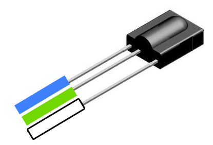
The infrared receiver typically has three pins or solder pads. When viewing the sensor from the top with the hemispherical receiver lens facing toward you, the connections are standardized:
- Left terminal: Solder the blue wire to this position (signal output)
- Middle terminal: Solder the green wire to this position (ground reference)
- Right terminal: Solder the white wire to this position (5V power input)
Apply heat to both the terminal and wire simultaneously, then introduce solder to create a strong mechanical and electrical connection. Each joint should be smooth and shiny—a dull, grainy appearance indicates a cold solder joint that may be unreliable.
Actuator Wiring Harness Modification
FIRGELLI track actuators typically include a wired control pendant with up/down buttons. To integrate with the Arduino control system, you'll modify this wiring harness to connect directly to the relay module.
Disassembling the Wired Remote Control
The pendant remote contains a simple circuit board with momentary contact switches. Using the #0 Phillips screwdriver, remove the terminal screws on the back of the remote housing. These screws secure the actuator power wires to the circuit board assembly. Once loosened, the wires can be withdrawn and the circuit board removed from the housing.
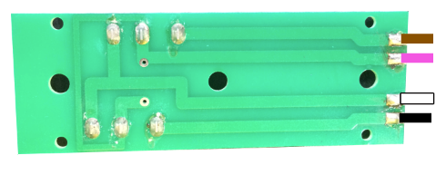
Identifying Wire Functions
Examine the circuit board from the component side. Four wires should be soldered to solder pads on the board. From left to right, the standard color coding is black, white, purple, and brown. If your actuator uses different colors, note their positions carefully as the order is what matters, not the specific colors themselves.
These wires form two circuits—each momentary switch in the remote completes one circuit when pressed, causing the actuator to move in one direction. The relay module will electronically replicate this switching action.
Desoldering the Wires
Heat each solder joint individually with the soldering iron while gently pulling the wire with small pliers. The goal is to soften the existing solder sufficiently that the wire releases without excessive force. Work carefully to avoid damaging the wire insulation, as these wires will be reused. A desoldering pump or solder wick can help remove excess solder if needed.
Connecting Wires to Relay Terminals
The relay module has screw terminals designed for wire insertion. The specific terminal assignments are critical for proper operation:
- White wire: Insert into K1 position 1 and secure with terminal screw
- Black wire: Insert into K1 position 2 and secure with terminal screw
- Brown wire: Insert into K2 position 2 and secure with terminal screw
- Purple wire: Insert into K2 position 3 and secure with terminal screw
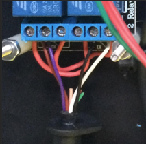
Important: The jumper wires you installed earlier between K1 and K2 terminals should remain in place. The terminal blocks can accommodate multiple wires—simply loosen the screw, insert the wire alongside the existing jumper, and retighten securely.
Breadboard Wiring and Power Distribution
The breadboard serves as a junction point for power distribution and signal routing. Each horizontal row of holes in a breadboard is electrically connected, allowing multiple components to share common connections without requiring wire splicing.
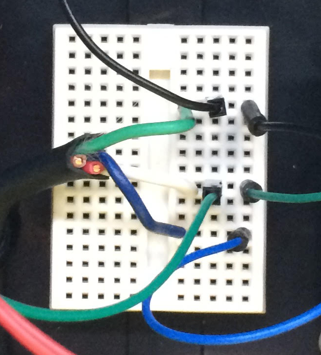
5V Power Distribution
The 5V power rail must supply both the relay module and the infrared receiver. Using the breadboard to create a common power bus simplifies wiring:
- Connect a male-to-female jumper wire from the Arduino's 5V power terminal to any unused row on the breadboard
- Connect a second jumper wire from the same breadboard row to the VCC terminal on the relay module
- Strip ¼" from the white wire of the 18/5 cable (opposite end from the infrared sensor) and insert it into the same breadboard row
All three connections now share the regulated 5V supply from the Arduino board.
Ground Distribution
Similarly, all components require a common ground reference:
- Connect a jumper wire from the Arduino's GND terminal to a different unused row on the breadboard
- Connect a jumper wire from the relay module's GND terminal to the same breadboard row
- Strip ¼" from the green wire of the 18/5 cable and insert it into the same breadboard row
Signal Connection
The infrared sensor's output connects to Arduino digital pin 11:
- Connect a jumper wire from Arduino digital pin 11 to another unused breadboard row
- Strip ¼" from the blue wire of the 18/5 cable and insert it into the same breadboard row
This completes the physical wiring of the control circuit. Double-check all connections against the instructions before proceeding to software installation.
Arduino Programming and Software Configuration
The Arduino must be programmed with custom code that decodes TiVo remote signals and activates the appropriate relay channels. This section covers software installation, code upload, and a critical library modification.
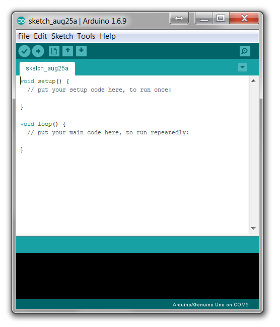
Installing the Arduino IDE
The Arduino Integrated Development Environment (IDE) is free software available from Arduino's official website. Download and install the version appropriate for your operating system (Windows, macOS, or Linux). The IDE provides code editing, compilation, and upload capabilities necessary for programming the Arduino board.
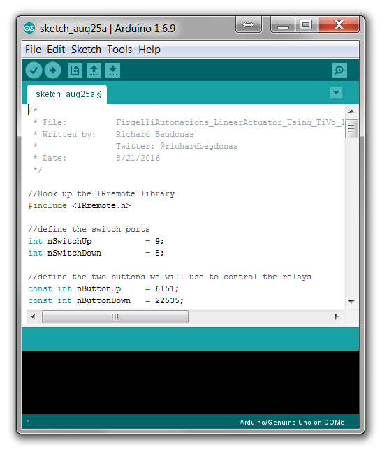
Loading the Project Code
The complete source code for this project is available on GitHub. Copy the entire code and paste it into a new sketch in the Arduino IDE. The code includes several key functions:
- Infrared signal decoding using the IRremote library
- Button code identification for TiVo thumbs up and thumbs down buttons
- Relay activation logic with interlocking to prevent simultaneous activation
- Timeout functionality to prevent continuous operation
The code is structured to be easily modified if you want to use different buttons or add additional functionality such as position memory or obstacle detection integration.
Critical Library Modification
A known issue exists in the RobotIRremote library that ships with the Arduino IDE. Before uploading code, you must correct this issue or compilation will fail.
Navigate to C:\Program Files (x86)\Arduino\libraries\RobotIRremote\src\ and open the file IRremoteTools.cpp in a text editor such as Notepad. Locate line 5, which should read:
int RECV_PIN = TKD2; // the pin the IR receiver is connected to
Change this line to:
int RECV_PIN = 11; // the pin the IR receiver is connected to
Save the file and close the text editor. This modification ensures the library correctly references digital pin 11 where the infrared receiver is connected in this project.
Uploading Code to the Arduino
Connect the Arduino to your computer using the USB cable—the rectangular Type-A connector plugs into your computer, while the square Type-B connector attaches to the Arduino board. The Arduino's power LED should illuminate, indicating it's receiving power through the USB connection.
In the Arduino IDE, select Tools → Port and choose the COM port that corresponds to your Arduino board. The port listing typically indicates "Arduino Uno" to help you identify the correct port.
Select Sketch → Upload to compile the code and transfer it to the Arduino. During upload, you'll see TX and RX LEDs flashing on the Arduino board as data transfers. When complete, the IDE displays "Done uploading" and the Arduino automatically begins running the program.
System Testing and Functional Verification
Before final assembly in the project enclosure, thorough testing ensures all components function correctly and connections are reliable.
Initial Power-Up Test
With the Arduino still connected to your computer via USB and all components wired according to the instructions, connect the modified wiring harness to your FIRGELLI track actuator. Plug the actuator's power supply into a wall outlet. The actuator should not move at this point—movement without input would indicate a wiring error or relay failure.
Remote Control Function Testing
Position the TiVo remote control so it points toward the infrared receiver. The sensor has a hemispherical reception pattern, but best results occur when the remote is pointed directly at the sensor from a distance of 6-15 feet.
Press the green "thumbs up" button on the TiVo remote. You should hear the relay click as it activates, and the actuator should begin extending. The actuator will continue moving as long as you hold the button, up to any timeout value programmed in the code.
Press the red "thumbs down" button. The first relay should deactivate (you may hear a click), the second relay should activate (another click), and the actuator should reverse direction and begin retracting.
Troubleshooting Common Issues
If the actuator doesn't respond to remote commands, systematically check the following:
- Infrared reception: The Arduino IDE's Serial Monitor can display received IR codes. Open it at 9600 baud to verify the Arduino is receiving signals when you press remote buttons.
- Relay activation: You should hear relays clicking. If not, verify the relay module power connections and that the Arduino code is running (the onboard LED may flash during operation).
- Actuator wiring: If relays activate but the actuator doesn't move, verify the four wires from the actuator are connected to the correct relay terminals. Reversing certain wires will prevent operation.
- Power supply: Ensure the actuator's power supply is connected and providing appropriate voltage. Most FIRGELLI actuators operate on 12V DC.
Final Assembly in Project Enclosure
Once testing confirms proper operation, the components can be permanently mounted in the Hammond project box. This enclosure provides physical protection for the electronics and creates a professional-looking finished product.
Preparing the Enclosure
The ABS plastic enclosure must be modified to accommodate wire entry points and allow the infrared sensor to receive signals. A heated soldering iron tip can be used to melt precise holes through the plastic—this technique provides cleaner results than drilling, which can crack ABS.
Create the following openings:
- One opening for the USB cable (if you plan to power the Arduino via USB rather than adding an internal power supply)
- One opening for the infrared sensor cable
- One opening for the actuator wiring harness
- One opening that allows infrared light to reach the sensor (alternatively, mount the sensor outside the enclosure)
Mounting Components with Standoffs
The #4-40 machine screws, nylon spacers, and nuts create standoffs that securely mount the Arduino, relay module, and breadboard inside the enclosure while preventing short circuits against the metal or conductive surfaces.
Stack the components as follows for each mounting point:
- Machine screw through the enclosure bottom
- Nylon spacer on the screw inside the enclosure
- Circuit board mounting hole over the screw
- Second nylon spacer on top of the circuit board
- Nut threaded onto the screw to secure the assembly
This arrangement provides approximately 1" of clearance beneath components and prevents them from contacting the enclosure bottom. Tighten nuts firmly but not excessively—overtightening can strip the threads in the nylon spacers or crack circuit boards.
Cable Strain Relief
Use a zip tie to secure the infrared sensor cable near where it enters the enclosure. This prevents tension on the wire from being transmitted to the soldered connections on the sensor, which could eventually fail from mechanical stress. FIRGELLI actuators include a rubber grommet on their cables for similar strain relief—ensure this remains in place.
Integration Considerations for Hidden TV Systems
While this project demonstrates the core electronics and control system, successful integration into a hidden TV installation requires additional mechanical design considerations.
Mounting Artwork or Covering Panel
The track actuator mounts behind the wall or in cabinetry, with its shaft connected to the artwork frame or panel. Proper alignment is critical—the actuator shaft must move perpendicular to the panel surface to avoid binding. Mounting brackets designed for FIRGELLI actuators simplify installation and provide adjustment for alignment.
Stroke Length Selection
Select an actuator stroke length that provides sufficient travel to fully reveal the television. Measure the vertical distance from the top of the TV screen to the desired resting position of the artwork's bottom edge, then add 2-3 inches for clearance. FIRGELLI offers track actuators in stroke lengths from 6" to 60", accommodating virtually any installation requirement.
Load Capacity and Safety
Track actuators are rated for specific force capacities, typically ranging from 35 lbs to 220 lbs depending on model. Calculate the weight of your artwork, frame, and mounting hardware, then select an actuator with capacity exceeding this weight by at least 25%. This safety margin ensures reliable operation and long service life. For particularly heavy installations, consider upgrading to an industrial actuator designed for demanding applications.
Guide Rails for Panel Stability
Large panels benefit from slide rails or linear guides that prevent wobbling during motion. These guides mount parallel to the actuator and constrain the panel to pure vertical motion, eliminating side-to-side movement that can appear unprofessional or damage the installation over time.
System Expansion and Enhancement Options
The Arduino-based control platform provides a foundation for additional automation features beyond basic up/down control.
Position Feedback Integration
Standard track actuators move until a limit switch engages or power is removed. Feedback actuators include built-in potentiometers or Hall effect sensors that provide real-time position data. By connecting this feedback signal to an Arduino analog input, you can implement precise position control, allowing the panel to stop at intermediate positions or return to exact positions from memory.
Multiple Actuator Synchronization
Very large or wide panels may require two actuators operating in synchronization. The relay module approach can be expanded by adding additional relay channels, or an control box designed for synchronized multi-actuator operation can simplify wiring. Synchronized operation ensures panels remain level during motion.
Smart Home Integration
The Arduino can be enhanced with WiFi or Bluetooth capability through add-on shields or modules. This enables integration with home automation platforms like Home Assistant, Amazon Alexa, or Google Home, allowing voice control or automated operation based on time schedules or other triggers.
Obstacle Detection
Safety features can be implemented using infrared proximity sensors or current sensing on the actuator power circuit. If an obstacle prevents actuator motion, current increases as the motor stalls. Detecting this condition allows the Arduino to automatically reverse direction, preventing damage or injury.
Maintenance and Longevity
Properly installed electric linear actuators require minimal maintenance but benefit from occasional inspection and care.
Periodic Inspection
Every 6-12 months, inspect the installation for:
- Loose mounting screws on actuator or panel attachments
- Worn or damaged guide rails or bearings
- Frayed or damaged electrical connections
- Dust accumulation on electronics (use compressed air for cleaning)
- Proper infrared sensor function (verify remote response remains reliable)
Actuator Care
FIRGELLI actuators feature sealed construction protecting internal components from dust and moisture. However, keeping the installation environment reasonably clean extends service life. The shaft should not require lubrication—applying lubricants can attract dust that eventually causes premature wear. If the actuator becomes noticeably slower or noisier, contact FIRGELLI technical support for evaluation.
Electronic Component Life
Relay modules have finite switching lifespans, typically rated for 100,000+ operations. For a hidden TV system cycled twice daily, this represents decades of service. If a relay eventually fails, the entire relay module can be replaced without modifying other aspects of the system.
Conclusion
This project demonstrates how hobby electronics and professional-grade motion control components can be combined to create sophisticated home automation systems. By leveraging the TiVo remote you already use daily, the system integrates seamlessly into your entertainment experience without adding complexity. The Arduino platform provides flexibility for future enhancements while remaining accessible to DIY builders.
The combination of FIRGELLI's track actuators with custom control electronics represents a cost-effective alternative to commercial hidden TV systems that often cost thousands of dollars. Beyond cost savings, the custom approach allows precise tailoring to your specific installation requirements, artwork dimensions, and control preferences.
Whether you're concealing a television behind artwork, within furniture, or integrated into architectural features, the principles demonstrated here scale to accommodate various installation types. The skills developed through this project—working with Arduino microcontrollers, relay modules, infrared control, and linear actuators—transfer to countless other automation applications throughout your home.


