Why Restrict Linear Actuator Stroke Length?
In many motion control applications, you don't need—or want—to use the full stroke length of a linear actuator. Whether you're building a custom TV lift that needs to stop at a specific viewing height, creating an automated window opener with precise positioning, or designing machinery where safety requires travel restrictions, controlling the exact range of motion is critical.
🎥 Video — Restricting Linear Actuator Stroke using external limit switches
While all FIRGELLI linear actuators (except the Bullet Mini and Bullet 23 Cal.) come with built-in limit switches at the fully extended and retracted positions, these internal limits are fixed and non-adjustable. This is where external limit switches become essential. By adding external limit switches to your actuator system, you gain complete control over the travel range, allowing you to set custom end points anywhere along the stroke length.
This comprehensive guide will explain how limit switches work, when you need external switches, and provide detailed installation instructions with wiring diagrams to help you successfully restrict your actuator's stroke length for any application.
How Limit Switches Work in Linear Actuator Systems
A limit switch is an electromechanical device that acts as a safety mechanism and position control element. At its core, a limit switch is a spring-loaded button or lever that, when pressed by the moving actuator rod or carriage, opens an electrical circuit. This interruption stops current flow to the motor, immediately halting further movement in that direction.
The brilliance of a properly designed limit switch circuit lies in its directional control. When the switch is triggered, it doesn't simply cut all power—it specifically prevents motion in one direction while still allowing reverse movement. This is accomplished through a diode wired across the switch terminals.
The Role of Diodes in Limit Switch Circuits
A diode is a semiconductor component that allows electrical current to flow in only one direction, functioning much like a one-way valve in a hydraulic system. In limit switch applications, this directional property is critical for proper operation.
When a limit switch is pressed and opens the circuit, the diode wired in parallel across its terminals provides an alternate current path—but only for current flowing in the opposite direction. This means:
- When extending to the limit, the switch opens and stops extension
- The diode allows current to flow in reverse, permitting retraction
- When retracting to the limit, that switch opens and stops retraction
- Its diode allows current to flow forward, permitting extension
Without diodes, an actuator would become completely locked once either limit switch was triggered, unable to move in any direction. The diode configuration ensures that reaching a limit never results in a permanently disabled actuator—you can always reverse direction to move away from the limit position.
Built-In Limit Switches vs. External Limit Switches
Understanding Internal Limit Switches
All FIRGELLI linear actuators—with the exception of certain compact bullet actuators—incorporate internal limit switches at the fully extended and fully retracted positions. These are built into the actuator housing during manufacturing and serve essential protective functions:
- Motor Protection: Prevent the motor from stalling under load at the end of travel, which would cause overheating and potential burnout
- Mechanical Protection: Stop the actuator before internal components reach destructive stress points
- Reliability: Ensure consistent, repeatable end positions across millions of cycles
- Automatic Operation: No external sensors or programming required for basic end-of-stroke protection
However, these internal limits have one significant limitation: they're permanently positioned at the manufacturer-specified maximum and minimum stroke positions. You cannot adjust them without disassembling the actuator (which would void your warranty).
When You Need External Limit Switches
External limit switches become necessary when your application requires any of the following:
- Restricted Extension: You need the actuator to stop extending before reaching its full stroke length—common in applications where full extension would cause clearance issues or exceed safe working angles
- Restricted Retraction: You want to prevent full retraction, keeping the actuator partially extended as a minimum position—useful in applications like adjustable-height tables where a minimum height must be maintained
- Both-Direction Restriction: You need a window of travel somewhere in the middle of the actuator's stroke range, not using either extreme position
- Multiple Position Stops: You want to create intermediate stopping points for multi-position applications
- Adjustable Limits: Your application may need different travel ranges at different times, and external switches can be repositioned
Applications commonly requiring external limit switches include automated furniture where dimensions must match existing cabinetry, robotic systems with workspace boundaries, safety gates that must not over-travel, and any custom machinery where stroke length doesn't perfectly match available actuator specifications.
Installing External Limit Switches: Complete Guide
Materials and Tools Required
Before beginning installation, gather the following items:
- FIRGELLI External Limit Switch Kit (includes limit switches with pre-wired diodes and optional fuses)
- Crimping tool or soldering iron for wire connections
- Heat shrink tubing or electrical tape for insulation
- Small screws or bolts for mounting switches (size depends on your application materials)
- Drill and appropriate bits if mounting points need to be created
- Wire strippers
- Multimeter (optional but recommended for testing)
Step 1: Determine Limit Positions
The most critical step in external limit switch installation is accurately determining where your travel limits need to be:
- Install Your Actuator: Mount the linear actuator in its final position within your application using appropriate mounting brackets
- Test Full Range: Operate the actuator through its complete stroke to understand the available travel
- Mark Desired Limits: Manually move the actuator to your desired maximum extension point and mark this location. Repeat for your desired minimum position if restricting retraction
- Account for Switch Activation: Remember that the switch must be triggered before the actuator reaches the absolute limit—position switches so they're activated with at least 3-5mm of remaining travel
- Consider Collision Force: The actuator will strike the limit switch with force. Ensure your mounting location can withstand repeated impacts without damage or switch misalignment
Step 2: Mount the Limit Switches
Secure physical mounting is essential for reliable operation:
- Mounting Surface: Attach switches to a fixed structural element that won't flex or move. The switch must be stationary while the actuator moves
- Alignment: Position each switch so the actuator rod, mounting bracket, or attached load will strike the switch button squarely—off-center impacts can cause premature switch failure
- Clearance: Ensure the switch body doesn't interfere with actuator movement and that wiring has adequate clearance
- Fastener Security: Use lock washers or thread-locking compound to prevent vibration-induced loosening over time
- Testing Movement: After mounting but before wiring, manually cycle the actuator to verify switches are activated cleanly at the correct positions
For applications with high precision requirements or where repositioning may be needed, consider using slotted mounting holes or adjustable brackets that allow fine-tuning of switch position.
Step 3: Wiring for Single Limit Switch (Extension or Retraction Only)
If you're restricting travel in only one direction, use the following wiring configuration:
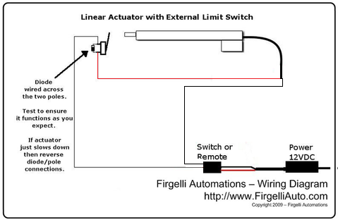
The single-switch configuration interrupts power to one motor terminal, preventing motion in one direction while allowing reverse movement through the diode. Note that the diodes come pre-installed on the FIRGELLI external limit switch kit, wired across the switch terminals—you don't need to add or modify these.
Key wiring points for single-switch installation:
- The limit switch is wired in series with one of the motor power leads
- Polarity matters—ensure you're interrupting the correct motor lead for your desired limit direction
- For limiting extension: wire the switch into the positive motor lead
- For limiting retraction: wire the switch into the negative motor lead
- The optional fuse can be added in series with the switch for additional overcurrent protection
- All connections should be crimped or soldered, then insulated with heat shrink tubing
Step 4: Wiring for Dual Limit Switches (Both Extension and Retraction)
When restricting travel in both directions, creating a defined window of operation within the actuator's full stroke, use this dual-switch configuration:
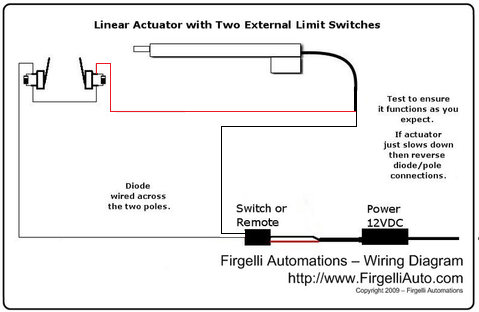
The dual-switch setup places one limit switch in each motor power lead. Each switch controls one direction of travel independently:
- The extension limit switch (positive lead) stops outward motion but allows retraction
- The retraction limit switch (negative lead) stops inward motion but allows extension
- The actuator can move freely between the two switch positions
- Both switches have diodes that permit reverse current flow
- Fuses are optional on both leads for comprehensive overcurrent protection
This configuration is ideal for applications like adjustable shelving systems, automated windows, or any mechanism where both minimum and maximum positions fall within the actuator's available stroke range.
Wire Connection Best Practices
Proper electrical connections are crucial for long-term reliability:
- Crimping: Use quality crimp connectors sized for your wire gauge. Poor crimps are the leading cause of external limit switch failures
- Soldering: If soldering, use rosin-core electrical solder and ensure joints are mechanically sound before soldering (not relying on solder for mechanical strength)
- Insulation: Cover all exposed connections with heat shrink tubing rather than electrical tape when possible—heat shrink provides better moisture protection and won't unravel over time
- Strain Relief: Secure wiring near connections to prevent wire movement from stressing joints
- Wire Routing: Route wires away from pinch points and moving parts, using cable ties to secure them to stationary structures
- Testing: Before full installation, test the circuit with a multimeter to verify switches open and close correctly
Optional Fuse Protection
The FIRGELLI external limit switch kit includes optional inline fuses. While not mandatory for basic operation, fuses provide an additional layer of protection against electrical faults:
- Overcurrent Protection: Fuses will blow if current exceeds safe levels due to a short circuit or motor stall, protecting your actuator and power supply
- Component Protection: In the event of switch failure, a fuse can prevent damage to the actuator's internal electronics
- Fire Prevention: Fuses reduce fire risk in installations where wiring could be damaged or insulation could fail
Fuse ratings should match or slightly exceed the actuator's maximum current draw. For most standard 12V linear actuators, a 5-10 amp fuse is appropriate, while high-force industrial actuators may require higher ratings. Always consult your actuator's specifications.
Troubleshooting External Limit Switch Issues
Actuator Won't Reverse After Hitting Limit
If your actuator stops at the limit switch but won't move in the opposite direction:
- Check that the diode across the limit switch terminals is properly installed and oriented correctly
- Verify the diode hasn't failed—test with a multimeter in diode test mode
- Ensure wiring connections are secure and haven't loosened
- Confirm you're actually attempting to reverse direction (easy to overlook in troubleshooting)
Limit Switch Not Triggering
If the actuator travels past where the limit should stop it:
- Verify the actuator is actually making contact with the switch button with sufficient force
- Check that the switch is securely mounted and hasn't shifted position
- Test the switch with a multimeter to ensure it's functioning (continuity should disappear when pressed)
- Inspect wiring for breaks or loose connections
- Ensure the switch is wired into the correct motor lead for your desired limit direction
Intermittent or Unreliable Switching
If limits work sometimes but not consistently:
- Check for loose mounting that allows the switch to move or vibrate out of position
- Inspect wire connections—intermittent issues are often caused by poor crimps or cold solder joints
- Verify that vibration hasn't loosened mounting screws
- Look for wire damage from pinching, abrasion, or repeated flexing
- Consider if temperature changes are affecting connections or switch operation
Advanced External Limit Switch Applications
Creating Multiple Position Stops
For applications requiring more than two positions—such as a multi-height desk or adjustable shelving—you can implement multiple external limit switches along the stroke length. This requires more complex control logic using a control box or microcontroller like Arduino, but the basic limit switch principles remain the same.
Integration with Feedback Actuators
While external limit switches provide physical position limiting, feedback actuators offer electronic position sensing. Combining both approaches gives you the precision of electronic positioning with the safety backup of mechanical limit switches—ideal for critical applications where position accuracy is essential.
Adjustable Limit Systems
For applications where limit positions may need adjustment during use, consider mounting limit switches on sliding brackets or using multiple switches with a selector mechanism. This allows repositioning without rewiring and can enable user-adjustable travel ranges in commercial products.
Conclusion
External limit switches provide precise, reliable control over linear actuator stroke length, enabling custom motion ranges for any application. By understanding how limit switches and their integrated diodes function, following proper installation and wiring procedures, and choosing appropriate mounting locations, you can successfully restrict your actuator's travel to exactly the range your project requires.
Whether you're working with micro linear actuators in compact electronics or heavy-duty industrial actuators in machinery, the principles of external limit switches remain consistent. The FIRGELLI external limit switch kit provides all necessary components with pre-wired diodes, making installation straightforward even for those new to motion control systems.
Frequently Asked Questions
Do I need to install both extension and retraction limit switches?
No, you only need to install limit switches for the direction(s) you want to restrict. If you only need to limit extension but want full retraction capability, install just one limit switch. Many applications only require limiting in one direction. However, if you need to create a specific window of travel that doesn't use the actuator's full stroke, you'll need both extension and retraction limits installed.
Will my actuator's internal limit switches still work after installing external ones?
Yes, the internal limit switches remain fully functional. External limit switches are wired in series with the motor power leads, so they simply create additional stop points before the actuator reaches its internal limits. The internal switches still provide backup protection if an external switch fails or if you need to bypass the external limits for maintenance.
Can I use any limit switch, or do I need the FIRGELLI kit?
While you can technically use any appropriately rated limit switch, the critical requirement is that each switch must have a diode wired across its terminals to allow reverse current flow. The FIRGELLI external limit switch kit comes with these diodes pre-installed and properly oriented, eliminating the risk of incorrect wiring. If using third-party switches, you must add diodes yourself (typically 1N4001 or equivalent) with correct polarity, and select switches rated for your actuator's voltage and current.
What if I need to adjust the limit positions after installation?
External limit switches can be repositioned at any time by simply unmounting them and moving them to new locations along the actuator's travel path. This is one of the key advantages over internal limits—complete adjustability. For applications where frequent adjustment is needed, consider mounting switches on slotted tracks or using multiple switches at different positions with a selection mechanism.
How much force will the actuator apply to the limit switch?
The force applied to the limit switch depends on your actuator's force rating and the control system's response time. An actuator doesn't stop instantly when the limit switch opens—momentum carries it slightly further. High-force actuators (over 200 lbs) moving at full speed can impact switches quite hard. Ensure switches are robustly mounted to structural elements that won't flex, and position them so the actuator has a small buffer of travel remaining to absorb the stopping momentum. Quality limit switches are designed to withstand thousands of activation cycles at typical impact forces.


