Second-Class Lever Calculator — Calculate Actuator Force Required
A second-class lever is a simple machine where the load is positioned between the fulcrum and the effort. This arrangement gives a mechanical advantage greater than 1, meaning you can lift a heavy load with less force than the load weighs. Use the calculator below to determine the exact actuator or effort force required for any second-class lever configuration.
What Is a Second-Class Lever?
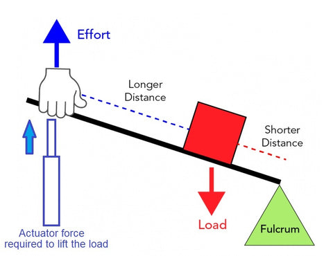
In a second-class lever, the load (weight) sits between the fulcrum (pivot point) and the point where effort is applied. The effort arm is always longer than the load arm, which creates mechanical advantage — a small force applied at the end of the lever can move a much heavier load closer to the fulcrum.
The mechanical advantage (MA) of a second-class lever is:
MA = Effort Arm Distance / Load Arm Distance
Because the effort arm is always longer than the load arm in a second-class lever, the MA is always greater than 1. This means second-class levers always amplify force.
Common Examples of Second-Class Levers
- Wheelbarrow — the wheel is the fulcrum, the load (dirt, rocks) sits in the bucket between the wheel and your hands, and your hands apply the effort at the handles
- Nutcracker — the hinge is the fulcrum, the nut (load) sits between the hinge and where you squeeze
- Bottle opener — the lip of the bottle is the fulcrum, the cap (load) is between the lip and where you push down
- Tonneau covers, hatches, and trap doors powered by linear actuators — the hinge is the fulcrum, the panel weight is the load, and the actuator provides the effort
Second-Class Lever Force Calculator
Results
Actuator Force Required F:
0 lbs
0 N
0 kg
0 g
The Formula: How the Calculator Works
The calculator uses the torque balance equation for a second-class lever:
Effort × Effort Arm = Load × Load Arm
Rearranged to solve for the effort (actuator force):
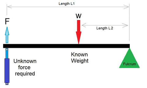
Effort Force (F) = (Weight W × Distance L1) / Distance L2
Where:
- W = the load weight or resistance being moved
- L1 = the distance from the fulcrum to where the load acts
- L2 = the distance from the fulcrum to where the effort force is applied
- F = the effort force required (this is what the calculator solves for)
Worked Example
Suppose you have a hatch that weighs 80 lbs. The hinge (fulcrum) is at one edge. The center of gravity of the hatch is 24 inches from the hinge (L1 = 24"). You plan to mount a linear actuator 48 inches from the hinge (L2 = 48").
F = (80 × 24) / 48 = 40 lbs of actuator force required
The mechanical advantage is 48/24 = 2.0, meaning you need only half the load weight in actuator force. Moving the actuator further from the hinge (increasing L2) increases the mechanical advantage and reduces the required force.
Distributed Loads: Tonneau Covers, Lids, and Panels
When the load is evenly distributed across the lever arm — as with a tonneau cover, a long lid, or a hinged panel — the weight acts as if it were concentrated at the midpoint of the loaded section. To use the calculator for distributed loads, enter L1 as half of the total panel length.

For example, if a tonneau cover is 100 inches long and weighs 60 lbs:
- L1 (load distance) = 100 / 2 = 50 inches (midpoint of the distributed load)
- L2 (actuator mounting point) = 100 inches (at the far end)
- F = (60 × 50) / 100 = 30 lbs of actuator force
This is a simplified calculation that assumes the actuator pushes perpendicular to the lever arm. In real-world hatch and lid applications, the actuator typically pushes at a changing angle as the lid opens. For these more complex geometries, use our Lid & Hatch Actuator Calculator, which accounts for the full angular arc and recommends specific actuators from our catalog.

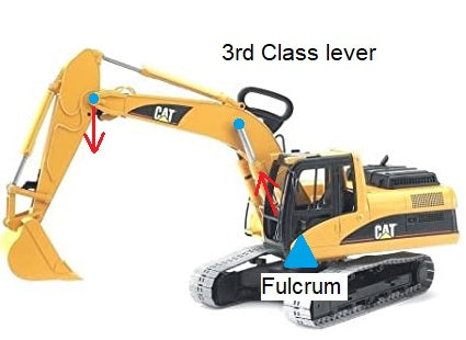
Second-Class Lever vs. Third-Class Lever
The key difference between second-class and third-class levers is the position of the effort relative to the load and fulcrum:
| Feature | Second-Class Lever | Third-Class Lever |
|---|---|---|
| Arrangement | Fulcrum — Load — Effort | Fulcrum — Effort — Load |
| Mechanical advantage | Always > 1 (amplifies force) | Always < 1 (amplifies speed/distance) |
| Effort vs. load force | Effort < Load weight | Effort > Load weight |
| Output speed | Slower than input | Faster than input |
| Examples | Wheelbarrow, nutcracker, hatch lid | Fishing rod, tweezers, human forearm |
| Actuator use | Heavy lids, hatches, trap doors | Fast-moving panels, flaps, robot arms |

When the Actuator Pushes at an Angle
The simple calculator above assumes the effort force is applied perpendicular to the lever arm. In most real-world actuator installations, the actuator pushes at a changing angle as the lever rotates — which means the effective perpendicular force component changes throughout the stroke.
For these angled-force situations, we have two specialized calculators:
- Second-Class Lever Angled Calculator — calculates the force when the effort is applied at a fixed angle to the lever arm
- Lid & Hatch Actuator Calculator — full interactive simulator that accounts for actuator mounting position, changing angles through the full opening arc, and recommends specific actuators

Related Lever Calculators and Engineering Guides
- First Class Lever Calculator — fulcrum between effort and load (seesaw, crowbar)
- Third Class Lever Calculator — effort between fulcrum and load (fishing rod, tweezers)
- Second Class Lever Angled Calculator — when the force is applied at an angle
- Compound Lever Calculator — multiple levers in series for high mechanical advantage
- Lid & Hatch Actuator Calculator — full interactive tool for hatch, lid, and pop-top roof actuator sizing
- Scissor Lift Calculator — force and stroke for scissor-lift mechanisms
- Full Calculator Suite — all FIRGELLI engineering calculators in one place
- Types of Linkages Guide — comprehensive guide to all mechanical linkage types
- Mastering Mechanical Advantage — levers, pulleys, gears, and hydraulics explained


