The Arduino revolution has transformed how engineers, makers, and DIY enthusiasts approach automation projects. What once required specialized knowledge in embedded systems programming can now be accomplished with accessible, open-source platforms. While blinking LEDs might be the traditional introduction to microcontrollers, the real power of Arduino emerges when you begin controlling physical systems — opening hatches, adjusting panels, lifting platforms, or automating mechanisms that require precise linear motion.
🎥 Video — How to Use an Arduino with Firgelli Automations Linear Actuators
Linear actuators are the workhorses of physical automation, converting electrical energy into controlled linear motion. Whether you're building an automated chicken coop door, a solar panel tracking system, a pop-up TV lift, or an adjustable standing desk, linear actuators provide the muscle while Arduino provides the brain. However, there's a critical challenge: Arduino boards operate at 5V logic levels and can only source about 40mA per pin, while most linear actuators require 12V or 24V DC power and draw several amperes under load. Direct connection would immediately damage your Arduino.
This guide provides a comprehensive approach to safely interfacing Arduino microcontrollers with FIRGELLI linear actuators using relay-based control circuits. We'll cover the fundamental concepts, detailed wiring instructions, complete Arduino code examples, and practical considerations for building reliable motion control systems.
Understanding the Power Challenge: Why You Can't Connect Actuators Directly
Arduino microcontrollers, whether you're using an Uno, Mega, or Nano, have strict electrical limitations. The digital output pins operate at 5V (or 3.3V for some models) and can safely source a maximum of 40mA per pin, with a total board limit typically around 200mA. These specifications are perfectly adequate for driving LEDs, small signal transistors, or logic-level devices.
Linear actuators, however, are electromagnetic devices that require substantially more power. A typical 12V DC linear actuator draws between 2-6 amperes during operation, with current peaks even higher during stall conditions or when moving against maximum load. Some industrial actuators can draw 10-15 amperes or more. This represents a power differential of 50 to 150 times what an Arduino pin can handle.
Furthermore, linear actuators are bidirectional devices — they extend and retract based on voltage polarity. To achieve this directional control, you need to reverse the polarity of the voltage applied to the actuator's motor terminals. This requires a switching mechanism capable of handling high current loads while responding to low-level logic signals from the Arduino.
The Relay-Based Control Solution
The most straightforward and reliable method for Arduino-actuator interfacing uses electromechanical relays. A relay is an electrically operated switch that uses a small current through a coil to control a much larger current through its contacts. The Arduino energizes the relay's coil (typically requiring only 15-30mA at 5V), and the relay's contacts switch the high-current actuator circuit.
For complete linear actuator control — extend, retract, and stop — you need two SPDT (Single Pole Double Throw) relays. SPDT relays are critical because they provide three connection points per relay: Common (COM), Normally Open (NO), and Normally Closed (NC). This configuration allows you to create an H-bridge circuit that can reverse actuator polarity.
Why SPDT Relays Are Essential
SPDT relays offer a significant advantage over simple SPST (Single Pole Single Throw) relays. When the relay coil is de-energized, the COM terminal connects to the NC terminal. When energized, COM switches to the NO terminal. This switching action allows you to direct current flow in either direction through the actuator motor, providing bidirectional control with just two relays.
Additionally, when both relays are de-energized, the circuit creates an electrical brake. Both actuator motor terminals connect to the same voltage rail (ground in the recommended configuration), causing the motor to short through itself. This dynamic braking stops the actuator almost immediately rather than allowing it to coast to a stop, providing precise position control even without position feedback.
Selecting Appropriate Relays
When choosing relays or relay modules for linear actuator control, consider these specifications:
- Coil Voltage: 5V for direct Arduino control, or 12V if you're using a separate control voltage with transistor drivers
- Contact Rating: Minimum 10A at 12V DC (for standard actuators); 15A or higher recommended for safety margin
- Contact Type: SPDT configuration required (often labeled as Form C or CO contacts)
- Coil Current: Less than 40mA for direct Arduino pin driving, or use relay modules with integrated driver transistors
- Protection: Look for relay modules with built-in flyback diodes to protect Arduino from inductive voltage spikes
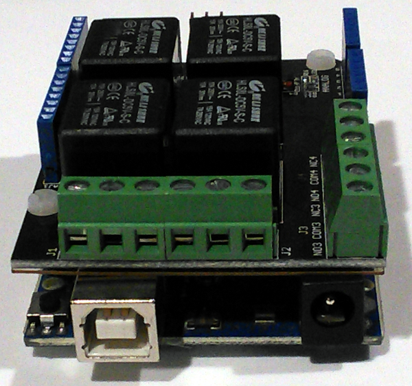
Pre-assembled relay modules designed for Arduino typically include driver transistors, flyback protection diodes, and LED indicators, making them ideal for prototyping and permanent installations alike.
Wiring Diagram and Connections
The wiring configuration for Arduino-controlled linear actuator operation requires careful attention to ensure safe, reliable operation. The circuit separates the low-voltage control signals from the high-current actuator power supply.
Power Supply Connections
Your actuator's power supply must be appropriately rated for the actuator's voltage and current requirements. Most FIRGELLI actuators operate on 12V DC, though some models use 24V. The power supply should provide at least 1.5 times the actuator's maximum rated current to ensure adequate capacity during peak loads.
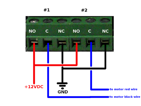
Connect the power supply as follows:
- Ground (negative): Connect to the NC (Normally Closed) terminals of both SPDT relays
- Positive (+12V): Connect to the NO (Normally Open) terminals of both SPDT relays
You can use wire splitters, terminal blocks, or short jumper wires to connect a single power supply wire to both relay terminals. Ensure all high-current connections use appropriate wire gauge — typically 18 AWG or heavier for actuators drawing more than 3 amperes.
Actuator Connections
Linear actuators have two motor terminals, often color-coded (red and black) or labeled. Connect each actuator wire to the COM (Common) terminal of one relay. It doesn't matter which actuator wire goes to which relay for initial setup — if the actuator moves in the opposite direction to your commands, simply swap these two connections.
Arduino Control Connections
Connect the relay control inputs to Arduino digital output pins. In the example code provided, we use pins 2 and 3, but any digital I/O pins can be used. Most relay modules require three connections per relay:
- VCC: Connect to Arduino 5V pin
- GND: Connect to Arduino ground
- IN: Connect to designated digital pin (e.g., pins 2 and 3)
Ensure your Arduino's ground shares a common reference with the relay module's ground, even though the actuator power supply remains isolated from the Arduino's power supply. Never connect the actuator's high-voltage power supply directly to the Arduino.
Arduino Code Implementation
The following Arduino code provides complete control over linear actuator operation, including extend, retract, and stop functions. This code uses clear function definitions that can be easily integrated into larger projects.
const int RELAY_1_A = 2;
const int RELAY_1_B = 3;

void setup() {
  pinMode(RELAY_1_A, OUTPUT);
  pinMode(RELAY_1_B, OUTPUT);

  // Initialize both relays to OFF state
  digitalWrite(RELAY_1_A, LOW);
  digitalWrite(RELAY_1_B, LOW);
}

void loop() {
  // Example: Extend actuator for 3 seconds
  extendActuator(1);
  delay(3000);

  // Stop actuator
  stopActuator(1);
  delay(1000);

  // Retract actuator for 3 seconds
  retractActuator(1);
  delay(3000);

  // Stop actuator
  stopActuator(1);
  delay(1000);
}

void extendActuator(int actuator) {
  // Energize relay A and de-energize relay B
  // This connects actuator terminal A to positive voltage
  // and actuator terminal B to ground
  digitalWrite(RELAY_1_A, HIGH);
  digitalWrite(RELAY_1_B, LOW);
}

void retractActuator(int actuator) {
  // De-energize relay A and energize relay B
  // This reverses polarity, retracting the actuator
  digitalWrite(RELAY_1_A, LOW);
  digitalWrite(RELAY_1_B, HIGH);
}

void stopActuator(int actuator) {
  // De-energize both relays
  // This creates a braking effect by shorting
  // both motor terminals to ground through the NC contacts
  digitalWrite(RELAY_1_A, LOW);
  digitalWrite(RELAY_1_B, LOW);
}
Code Explanation and Customization
The code structure uses three dedicated functions for actuator control, making it easy to integrate into complex automation sequences. The actuator parameter in each function is included to allow future expansion for controlling multiple actuators with different relay pairs.
The setup() function configures the relay control pins as outputs and initializes them to LOW (relays de-energized). This ensures the actuator starts in a stopped state when the Arduino powers up or resets.
The example loop() function demonstrates a simple extend-stop-retract-stop sequence. In a real application, you would replace this with your specific logic, potentially including sensor readings, timing conditions, or user inputs.
Advanced Control Patterns
For more sophisticated applications, you can implement various control patterns:
- Limit Switch Integration: Connect mechanical limit switches to Arduino digital inputs and check their state before extending or retracting to prevent over-travel
-
Timed Positioning: Use
millis()instead ofdelay()for non-blocking timing, allowing the Arduino to monitor sensors while the actuator moves - Sensor-Triggered Motion: Integrate motion sensors, temperature sensors, or light sensors to trigger actuator movement based on environmental conditions
- Serial Control: Add serial communication to control the actuator from a computer or other devices via USB or Bluetooth
Position Feedback Systems
While the basic relay control system provides open-loop operation, many applications benefit from knowing the actuator's precise position. FIRGELLI offers feedback actuators equipped with built-in potentiometers or Hall effect sensors that provide real-time position information.
Potentiometer Feedback Integration
Feedback actuators with potentiometers output a voltage that varies linearly with shaft position. This signal connects to an Arduino analog input (A0-A5), providing a 10-bit resolution (0-1023) position reading. With this feedback, you can implement closed-loop position control:
const int POSITION_PIN = A0;
int targetPosition = 512; // Middle position

void moveToPosition(int target) {
  int currentPosition = analogRead(POSITION_PIN);
  int tolerance = 5; // Allow small position error

  if (currentPosition < target - tolerance) {
    extendActuator(1);
    while (analogRead(POSITION_PIN) < target - tolerance) {
      // Continue extending until target reached
      delay(10);
    }
    stopActuator(1);
  } else if (currentPosition > target + tolerance) {
    retractActuator(1);
    while (analogRead(POSITION_PIN) > target + tolerance) {
      // Continue retracting until target reached
      delay(10);
    }
    stopActuator(1);
  }
}
This closed-loop control enables precise positioning, allowing your automation system to move the actuator to specific positions rather than relying solely on timing.
Selecting the Right Actuator for Your Arduino Project
FIRGELLI manufactures a comprehensive range of linear actuators suitable for Arduino-based projects, each designed for specific applications and load requirements.
Light-Duty Actuators
For hobbyist projects, prototypes, and applications requiring moderate force, light-duty actuators offer an excellent balance of performance and affordability. These units typically provide forces ranging from 10 to 150 pounds and stroke lengths from 2 to 12 inches. They're ideal for opening small hatches, adjusting panels, or automating lightweight mechanisms.
Industrial-Grade Options
When your application demands higher force capacity, longer stroke lengths, or enhanced environmental protection, industrial actuators provide the necessary performance. These units feature robust construction, sealed housings for dust and moisture resistance, and force ratings up to 2,200 pounds.
Specialty Configurations
Depending on your specific application, consider these specialized actuator types:
- Micro linear actuators: Compact units perfect for space-constrained applications or lightweight automation tasks
- Track actuators: Feature integrated guide rails for enhanced stability in side-load applications
- Bullet actuators: High-speed, low-force units ideal for rapid-cycling applications
- Rotary actuators: Convert linear motion to rotational movement for opening doors, lids, or covers
Essential Accessories and Components
Power Supplies
Selecting an appropriate power supply is critical for reliable actuator operation. The power supply must provide sufficient current capacity for your actuator's requirements while handling the inductive load characteristics of electric motors. Look for power supplies rated for at least 1.5 times your actuator's maximum current draw. For example, if your actuator draws 4A maximum, choose a power supply rated for at least 6A at the correct voltage (typically 12V or 24V).
Mounting Hardware
Proper mechanical mounting ensures your actuator operates smoothly and reliably. FIRGELLI offers mounting brackets designed specifically for our actuator series. These precision-machined brackets accommodate the pivoting motion required at both ends of the actuator, preventing binding and reducing mechanical stress. The MB1 bracket series, for instance, provides a standardized mounting solution that saves significant time during installation and allows for easy alignment adjustments.
Alternative Control Options
While Arduino provides exceptional flexibility, some applications may benefit from pre-assembled control solutions. FIRGELLI's control box systems offer plug-and-play operation with built-in safety features, while various remote control options provide convenient wireless operation for applications that don't require the programmability of Arduino.
Troubleshooting Common Issues
Actuator Not Responding
If the actuator doesn't move when commanded:
- Verify power supply connections and voltage with a multimeter
- Check that relay coils are energizing (most relay modules have LED indicators)
- Confirm relay contact ratings are adequate for your actuator's current draw
- Ensure Arduino pins are correctly configured as outputs in the code
- Test the actuator directly with the power supply to verify it's functional
Actuator Moves in Wrong Direction
If the actuator extends when you command retraction (or vice versa), simply swap the two actuator wire connections at the relay COM terminals. This reverses the polarity and corrects the direction.
Erratic or Intermittent Operation
Intermittent operation often indicates:
- Insufficient power supply capacity — upgrade to higher current rating
- Loose wiring connections — verify all screw terminals are tight
- Electrical noise affecting the Arduino — add a separate power supply for the Arduino rather than powering it from the actuator supply
- Inadequate relay contact ratings — replace with higher-rated relays
Arduino Resets During Actuator Operation
If the Arduino resets when the actuator starts or stops, this indicates voltage spikes from the inductive motor load. Solutions include:
- Power the Arduino from a separate, isolated power supply
- Add a large capacitor (1000μF or larger) across the actuator power supply terminals
- Ensure relay modules include flyback protection diodes
- Add snubber circuits (RC networks) across relay contacts
Safety Considerations and Best Practices
When implementing Arduino-controlled linear actuator systems, always prioritize safety:
- Overcurrent Protection: Use fuses or circuit breakers on the actuator power supply to prevent fire hazards from short circuits
- Limit Switches: Implement mechanical or electronic limit switches to prevent over-extension or over-retraction that could damage the actuator or surrounding equipment
- Emergency Stop: For applications involving potential pinch points or heavy loads, include an easily accessible emergency stop button that cuts power to the actuators
- Wire Management: Use appropriate wire gauge for all high-current connections and secure wiring away from moving parts
- Enclosure: House electronics in proper enclosures to prevent accidental contact with high-voltage connections
- Load Testing: Test your system under full load conditions before deploying in final application to ensure adequate power supply capacity and reliable operation
Expanding Your System: Multiple Actuator Control
Many applications require controlling multiple actuators simultaneously or sequentially. With Arduino's multiple digital I/O pins, scaling to control several actuators is straightforward. Each actuator requires its own pair of relays and two Arduino pins.
For example, controlling three independent actuators requires six relays and six Arduino digital pins. The code structure remains similar, with separate functions for each actuator or a modified function that accepts the actuator number as a parameter and controls the corresponding relay pair.
When controlling multiple high-current actuators, ensure your power supply provides adequate total current capacity, or use separate power supplies for each actuator to prevent voltage sag affecting operation.
Conclusion
Arduino microcontrollers and electric linear actuators form a powerful combination for creating sophisticated motion control systems. By understanding the electrical requirements, implementing proper relay-based switching circuits, and utilizing clean, modular code structure, you can build reliable automation systems for countless applications.
The relay-based control method described here provides a robust foundation for Arduino-actuator interfacing, offering complete directional control, electrical braking, and straightforward implementation. As you gain experience, you can expand to position feedback systems, multiple actuator control, and integration with sensors and communication systems.
Whether you're automating a home theater, building a solar tracking system, creating adjustable furniture, or developing industrial control systems, FIRGELLI's range of actuators combined with Arduino's flexibility provides the tools to bring your automation ideas to reality.
Frequently Asked Questions
Can I use 24V linear actuators with Arduino and relays?
Yes, absolutely. The relay-based control method works with any DC voltage actuator, whether 12V or 24V. The relays simply switch the actuator's power supply voltage — you just need to ensure your relays are rated for the voltage and current of your specific actuator. Use a 24V power supply for 24V actuators, and ensure relay contacts are rated for 24V DC switching (most standard relays support this). The Arduino control side remains at 5V logic levels regardless of the actuator voltage.
Do I need to buy separate relays or can I use a relay module?
Relay modules designed for Arduino are highly recommended, especially for beginners. These pre-assembled boards include the relays, driver transistors, flyback protection diodes, LED indicators, and convenient screw terminals all on one PCB. They're designed to interface directly with Arduino 5V logic levels and protect your microcontroller from voltage spikes. Look for "2-channel Arduino relay module" or similar products. While you can build a circuit with individual relays, transistors, and diodes, relay modules save time and reduce the chance of wiring errors.
How do I determine what current rating my relays need?
Check your linear actuator's specifications for its maximum current draw, typically listed as "no-load current" and "maximum load current." Choose relays rated for at least 1.5 times the maximum load current. For example, if your actuator draws 5A maximum, use relays rated for at least 7.5A, preferably 10A. Most FIRGELLI light-duty actuators draw 2-6A, so 10A relay modules work well. For industrial actuators that may draw 10-15A, you'll need heavy-duty relays rated for 15-20A or higher.
Can I add position feedback to any linear actuator?
FIRGELLI's feedback actuators come with built-in potentiometers or Hall effect sensors for position feedback. These provide a varying voltage signal (typically 0-5V or 0-10V) that corresponds to shaft position, which you can read with Arduino's analog inputs. Standard actuators without built-in feedback can sometimes be retrofitted with external sensors like string potentiometers or linear encoders, but this requires mechanical modifications. For projects requiring precise position control, starting with a feedback-equipped actuator is more practical and reliable.
Can I control my Arduino-actuator system wirelessly?
Yes, Arduino supports various wireless communication methods. You can add Bluetooth modules (HC-05, HC-06) for smartphone control, Wi-Fi modules (ESP8266, ESP32) for internet-based control, or RF modules (nRF24L01) for dedicated remote control. The actuator control code remains the same — you simply add code to receive wireless commands and trigger the appropriate actuator functions. For simple wireless remote control without programming, consider FIRGELLI's pre-made remote control systems designed specifically for actuator applications.
Can I control multiple actuators with one Arduino?
Absolutely. Each linear actuator requires two relays and two Arduino digital pins. An Arduino Uno has 14 digital I/O pins, so you can control up to 7 independent actuators (using all available pins). An Arduino Mega has 54 digital I/O pins, allowing control of up to 27 actuators. The limiting factor becomes power supply capacity — each actuator draws several amperes, so you may need multiple power supplies or a high-capacity supply. The code structure scales easily by creating arrays of pin numbers and using loops to control multiple actuators systematically.
Do I need limit switches to prevent over-extension?
Most FIRGELLI linear actuators include internal limit switches that automatically cut power when the actuator reaches full extension or retraction. These protect the internal mechanism from damage. However, external limit switches are recommended for applications where the actuator's full stroke might cause problems (like crushing objects or colliding with structures). You can connect external limit switches to Arduino digital inputs and modify your code to check switch states before commanding motion, adding an extra layer of safety and precision to your system.


