Designing a beam to carry a concentrated load at midspan is one of the most common problems in structural and mechanical engineering — and getting it wrong means either a failed structure or an over-engineered one that wastes material and cost. Use this Simply Supported Beam Center Point Load Calculator to calculate maximum deflection, bending moment, and shear force using beam length, applied load, elastic modulus, and moment of inertia. It's critical in building construction, machine frame design, and automation systems where linear actuators apply point loads to supporting structures. This page includes the governing formulas, a worked example, full technical theory, and an FAQ.
What is a simply supported beam center point load?
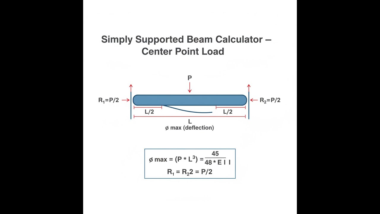
A simply supported beam is a beam resting on 2 supports that allow it to rotate freely at each end. A center point load is a single concentrated force applied exactly at the midpoint. The calculator tells you how much the beam bends and what internal forces it experiences.
Simple Explanation
Think of a diving board resting on 2 supports with someone standing right in the middle — that person's weight is the point load, and the board bending downward is the deflection. The stiffer the board and the shorter the span, the less it bends. This calculator tells you exactly how much bending to expect before you build anything.
📐 Browse all 1000+ Interactive Calculators
Simply Supported Beam - Center Point Load Diagram

Simply Supported Beam Point Load Calculator
How to Use This Calculator
- Select your unit system — Metric (SI) or Imperial (US).
- Enter the beam length (L), point load (P), elastic modulus (E), and moment of inertia (I) in the fields provided.
- Use the "Try Example" button to load a pre-filled worked example and check the expected output format.
- Click Calculate to see your result.
Simply Supported Beam interactive visualizer
Watch how beam deflection, moment, and shear forces change as you adjust the point load, beam length, and material properties. Visualize the critical relationships that determine whether your beam design will succeed or fail.
MAX DEFLECTION
0.25 mm
MAX MOMENT
2500 N⋅m
MAX SHEAR
2500 N
FIRGELLI Automations — Interactive Engineering Calculators
Mathematical Equations
Use the formula below to calculate maximum deflection, bending moment, and shear force for a simply supported beam with a center point load.
The simply supported beam point load calculator uses these fundamental structural analysis equations:
Maximum Deflection
δ = PL³ / (48EI)
Maximum Bending Moment
M = PL / 4
Maximum Shear Force
V = P / 2
Where:
- δ = Maximum deflection at beam center
- P = Applied point load
- L = Beam length
- E = Elastic modulus of beam material
- I = Second moment of area (moment of inertia)
- M = Maximum bending moment (occurs at center)
- V = Maximum shear force (occurs at supports)
Simple Example
A steel beam spans 2 m with a 5000 N load at the center. E = 200 GPa, I = 8.33 × 10⁻⁶ m⁴.
- Maximum deflection: δ = (5000 × 2³) / (48 × 200×10⁹ × 8.33×10⁻⁶) = 0.250 mm
- Maximum moment: M = (5000 × 2) / 4 = 2500 N⋅m
- Maximum shear: V = 5000 / 2 = 2500 N
Complete Technical Guide to Simply Supported Beam Analysis
Understanding how beams behave under concentrated loads is fundamental to structural engineering and mechanical design. The simply supported beam with a center point load represents one of the most common loading scenarios in engineering applications, from building construction to machine design.
Fundamental Principles of Beam Deflection
When a point load is applied to the center of a simply supported beam, several important phenomena occur simultaneously. The beam experiences bending, creating internal stresses that vary from compression on one side to tension on the other. The simply supported beam point load calculator helps engineers quantify these effects using established principles of structural mechanics.
The deflection equation δ = PL³/(48EI) reveals the critical relationships governing beam behavior. Notice that deflection increases with the cube of the beam length, making length the most sensitive parameter. Doubling the beam length increases deflection by a factor of eight, assuming all other variables remain constant.
Material Properties and Cross-Sectional Design
The elastic modulus (E) represents the material's stiffness - its resistance to deformation under stress. Common values include:
- Steel: 200 GPa (29,000 ksi)
- Aluminum: 70 GPa (10,200 ksi)
- Concrete: 30 GPa (4,350 ksi)
- Wood: 12 GPa (1,740 ksi)
The moment of inertia (I) depends entirely on the beam's cross-sectional shape and dimensions. For a rectangular cross-section with width b and height h, I = bh³/12. This cubic relationship with height explains why beams are typically oriented with their largest dimension perpendicular to the applied load.
Practical Applications in Engineering
Simply supported beams with center point loads appear frequently in real-world applications. Floor joists supporting concentrated equipment loads, bridge girders carrying vehicle weights, and machine frames supporting actuator loads all exhibit this behavior pattern. In automation systems, FIRGELLI linear actuators often create point loads on supporting structures, making accurate deflection calculations essential for system reliability.
Consider a material handling system where a linear actuator lifts a 500 kg load at the center of a 2-meter steel beam. Using our simply supported beam point load calculator, engineers can determine whether the beam deflection remains within acceptable limits and whether the induced stresses stay below material yield strengths.
Worked Example: Industrial Conveyor Support
Let's analyze a practical scenario: A conveyor system requires a support beam carrying a 1000 N concentrated load at its center. The beam spans 1.5 meters and has a rectangular steel cross-section measuring 50mm × 100mm.
Given parameters:
- Point load (P) = 1000 N
- Beam length (L) = 1.5 m
- Elastic modulus (E) = 200 × 10⁹ Pa
- Moment of inertia (I) = (0.05 × 0.1³)/12 = 4.17 × 10⁻⁶ m⁴
Calculations:
Maximum deflection: δ = (1000 × 1.5³)/(48 × 200×10⁹ × 4.17×10⁻⁶) = 0.844 mm
Maximum moment: M = (1000 × 1.5)/4 = 375 N⋅m
Maximum shear: V = 1000/2 = 500 N
This deflection of less than 1mm might be acceptable for many applications, but the engineer must also verify stress levels and consider dynamic factors.
Design Considerations and Safety Factors
Professional engineering practice requires considering multiple factors beyond basic calculations. Dynamic loading, fatigue effects, material variations, and construction tolerances all influence real-world performance. Most building codes require deflection limits of L/240 to L/360 for structural members, while precision machinery might demand much tighter tolerances.
Temperature effects can also be significant. Thermal expansion and contraction alter both the elastic modulus and physical dimensions, affecting calculated results. In applications involving FIRGELLI linear actuators, environmental temperature variations must be considered for precise positioning requirements.
Advanced Analysis Considerations
While the basic simply supported beam point load calculator provides excellent first-order analysis, complex structures may require more sophisticated approaches. Non-linear material behavior, large deflections, buckling potential, and dynamic loading all represent scenarios where advanced finite element analysis becomes necessary.
The shear deflection, typically negligible in long slender beams, can become significant in short, deep beams. For beams where the length-to-height ratio falls below 5:1, additional shear deformation terms should be included in deflection calculations.
Integration with Modern Design Tools
Today's engineers integrate fundamental calculations with computer-aided design tools and simulation software. However, hand calculations using tools like this simply supported beam point load calculator remain essential for preliminary design, concept validation, and checking computer results for reasonableness.
In automated systems design, beam deflection directly affects positioning accuracy. When designing supports for linear actuator systems, engineers must ensure that structural deflections don't compromise system performance. Our engineering calculators provide quick validation tools for these critical design decisions.
Frequently Asked Questions
📐 Browse all 1000+ Interactive Calculators →
About the Author
Robbie Dickson
Chief Engineer & Founder, FIRGELLI Automations
Robbie Dickson brings over two decades of engineering expertise to FIRGELLI Automations. With a distinguished career at Rolls-Royce, BMW, and Ford, he has deep expertise in mechanical systems, actuator technology, and precision engineering.
🔗 Related Engineering Calculators
More related engineering calculators:
- Simply Supported Beam Calculator Uniform Load
- Cantilever Beam Calculator Point Load At Free End
- Fixed Fixed Beam Calculator Uniform and Point Loads
- Cantilever Beam Calculator Uniform Distributed Load
- Beam Load Calculator Max Load for Given Beam
- Overhanging Beam Calculator Single Overhang
- Column Buckling Calculator Euler Critical Load
- Ratchet Mechanism Calculator Tooth Load and Size
- Circlip and Retaining Ring Load Calculator
- Center of Mass Multi Component Assembly Calculator
Browse all engineering calculators →
Need to implement these calculations?
Explore the precision-engineered motion control solutions used by top engineers.


