If you're planning a bracket, crane arm, or any overhang, you need a handle on how much your beam will bend and where the highest stress lands—before you fabricate anything. This Cantilever Beam Calculator gives you the max deflection, bending moment, and stress for a beam with a point load at the free end. Just enter your beam's length, the applied load, modulus of elasticity, and second moment of area. These numbers matter: too much deflection can throw off alignment or cause failure in automated equipment or structural work. Further down, you’ll find the calculation formulas, a worked example, technical notes, and an FAQ.
What is a cantilever beam point load?
A cantilever beam is fixed solidly at one end and free on the other. A point load, in this context, is a single force applied right at the free end. This setup tests how much the free tip will move and how much stress builds up where the beam is anchored.
Simple Explanation
Picture a diving board bolted to the deck. When someone stands at the very end, that's your point load. The board sags downward at the end, and all the force is resisted at the bolts. With this calculator, you’ll see both how far it bends and how much load the support actually needs to take.
📐 Browse all 1000+ Interactive Calculators
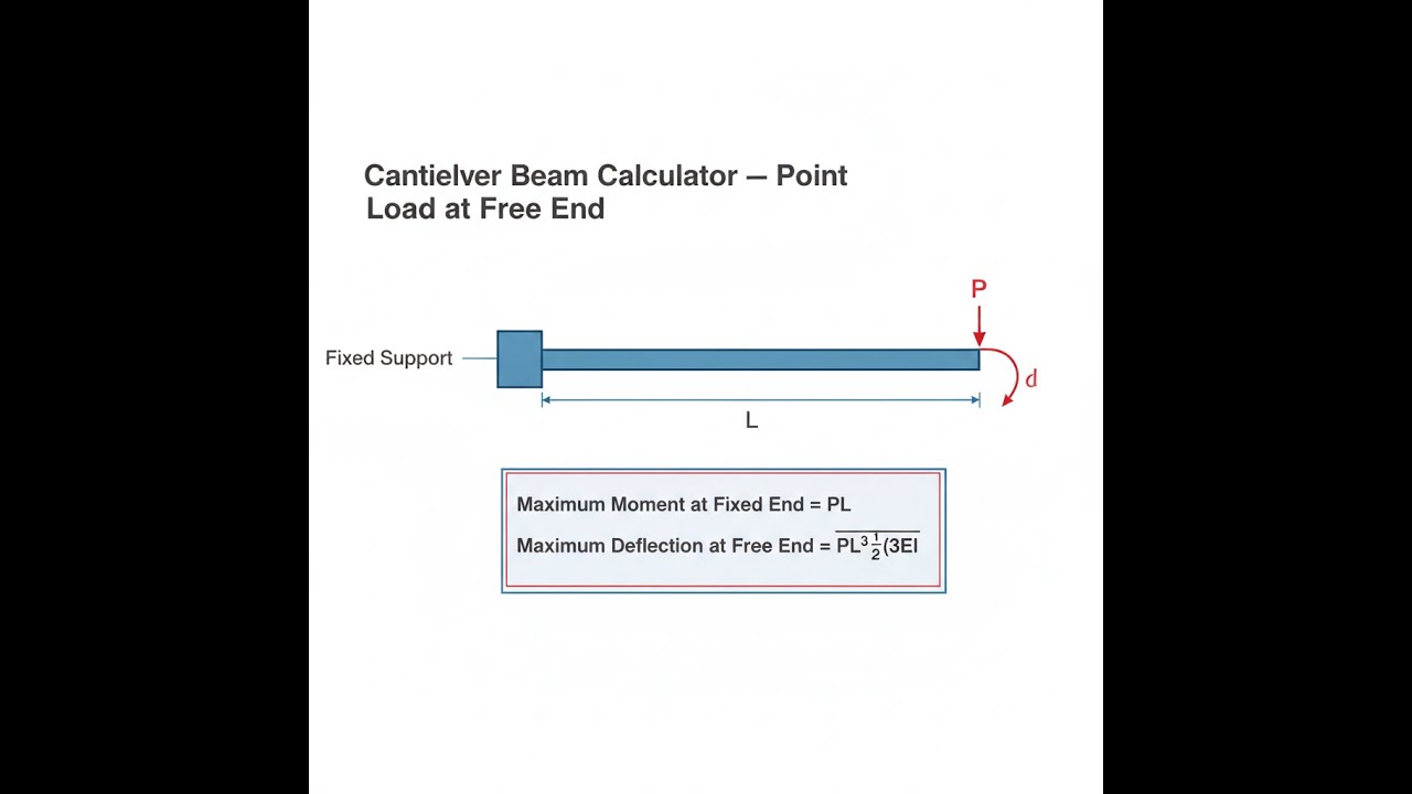
Cantilever Beam Diagram

Cantilever Beam Calculator
Cantilever Beam Calculator Interactive Visualizer
You can see right away how changing beam length, load, or stiffness alters deflection and stress. The cubic link between length and deflection stands out especially when you tweak the sliders.
MAX DEFLECTION
4.5 mm
MAX MOMENT
1500 N⋅m
DEFLECTION RATIO
L/333
FIRGELLI Automations — Interactive Engineering Calculators
How to Use This Calculator
- Enter the beam length (L) — measured from the fixed support to the free end.
- Enter the point load (P) — the force applied at the free end.
- Enter the modulus of elasticity (E) for your beam material — for steel, use 200 GPa.
- Click Calculate to see your result.
This calculator is intended for education, concept evaluation, and preliminary design. Results are based on the equations and assumptions described on this page, but cannot account for every real-world load case, tolerance, material property, environmental condition, installation detail, safety factor, code, or regulatory requirement. Verify all inputs, assumptions, units, and results independently before selecting components or using the result in a real application. Safety-critical, structural, medical, lifting, transportation, or regulated applications must be reviewed by a qualified engineer.
Questions about this calculator or found an error? Message our engineering team.
Mathematical Equations
Fundamental Formulas
Here's the formula to find the max deflection at the cantilever tip:
δ = PL³/(3EI)
To get the bending moment at the fixed end:
M = PL
For maximum bending stress at the fixed end, use:
σ = Mc/I = PLc/I
Variable Definitions:
- δ = Maximum deflection
- P = Point load applied at free end
- L = Length of cantilever beam
- E = Modulus of elasticity of beam material
- I = Second moment of area of beam cross-section
- M = Bending moment
- c = Distance from neutral axis to extreme fiber
- σ = Bending stress
Complete Technical Guide
Simple Example
Inputs: L = 1 m, P = 500 N, E = 200 GPa (200 × 10⁹ Pa), I = 8.33 × 10⁻⁶ m⁴
Maximum deflection: δ = (500 × 1³) / (3 × 200×10⁹ × 8.33×10⁻⁶) = 500 / 4,998,000 ≈ 0.0001 m = 0.1 mm
Maximum moment: M = 500 × 1 = 500 N·m
Understanding Cantilever Beam Mechanics
A cantilever beam with a point load at the tip is about as basic as load cases get in engineering. You'll see this setup in everything from wall brackets to machinery overhangs. The calculator helps you see at a glance if your setup will sag too much or produce unsafe stress before you ever cut material.
The mechanism is simple: put a point load on the tip, and the bending moment increases linearly from zero (free end) to the max at the fixed side. That moment diagram gives you all you need for deflection and stress: where the beam sags most, and where the fibers at the support are working the hardest.
Derivation of Deflection Formula
You get the deflection formula δ = PL³/(3EI) from basic beam theory, either by integrating bending equations or using the moment-area method. The main thing to watch for is the L³ term: even a small increase in length multiplies the deflection. E (modulus of elasticity) and I (moment of area) land in the denominator, so stiffer material and thicker (deeper) beam shapes keep bending in check.
This formula assumes you stay in the elastic range (no yielding), the beam deflects much less than its length, and the cross-section doesn't warp or twist abnormally. Most practical designs hit these requirements, as long as you haven't pushed into large deformations.
Practical Applications and Examples
Cantilever plus point load crops up often: crane jibs, small platforms, machine side-arms, or supports in automation. In automation, FIRGELLI linear actuators can stack considerable force onto a bracket or arm; a quick calculator check can prevent headaches later on.
Worked Example
Problem: Calculate the maximum deflection for a steel cantilever beam with the following specifications:
- Length (L) = 2.0 meters
- Point load (P) = 1000 N at free end
- Modulus of elasticity (E) = 200 GPa = 200 × 10⁹ Pa
- Second moment of area (I) = 8.33 × 10⁻⁶ m⁴
Solution:
δ = PL³/(3EI) = (1000)(2.0)³/(3 × 200×10⁹ × 8.33×10⁻⁶)
δ = (1000)(8)/(3 × 200×10⁹ × 8.33×10⁻⁶) = 8000/(4.998×10⁶) = 0.0016 m = 1.6 mm
Maximum Moment: M = PL = 1000 × 2.0 = 2000 N⋅m
Design Considerations and Best Practices
In most real designs, worry about deflection first—especially if things need to stay straight for machinery or automation. Building codes often set a max deflection like L/250 or L/360. If it bends more than that, you risk service issues long before you ever worry about breaking material.
Strength and stiffness both matter. High-strength steel won't help you much for deflection; pretty much all grades of steel have similar modulus (E). If deflection is the problem, making the beam section deeper is much more effective than picking a different steel grade. For a rectangle, second moment of area goes as h³—doubling the height cuts deflection down by 8×, but doubling width only halves it.
Shape optimization pays off the most: go for more depth if you want less sag, because moment of area dominates in the denominator of the formula.
Advanced Analysis Considerations
The formulas here work well as long as the deflection is much less than the span (typically, keep δ/L < 0.1). If the beam bends a lot, things get nonlinear and you'll need more advanced methods. If your system experiences vibration, resonance, or high-speed actuator movement, you'll need to consider dynamic effects—these can increase load on the support past what static analysis predicts.
In automated setups or fast actuator-driven motion, account for forces due to acceleration and deceleration. These transient loads might easily exceed the static payload. In those cases, build in a safety margin to cover dynamic amplification.
Connection to Other Structural Calculations
The cantilever beam point load solution forms the basis for more complex setup—continuous beams, frames, or loads at multiple locations. If your loading isn't as simple as a single tip point load, you can usually use superposition (sum up the effect of each load individually). If you’re combining point and distributed loads, calculate each and add the results. That keeps things simple and reliable.
Deflection and moment calculations for cantilevers are also often the first step for more detailed dynamic and vibration analyses—especially if you’re worried about bouncing or oscillation.
Quality Control and Verification
Double-check your results: hand calculations with these classic formulas are a good starting point. For complicated jobs, it’s worth running a quick prototype or simple physical test. Real-world results may deviate if you get the section properties wrong, use the wrong units, or ignore how flexible your support actually is. A real "fixed" support often has some give, so actual deflection can be a bit more than theory—keep that in mind if you’re working close to service limits.
Check especially near the fixed support; that's the highest stress and where small design mistakes have the biggest consequences.
Frequently Asked Questions
📐 Browse all 1000+ Interactive Calculators →
About the Author
Robbie Dickson
Chief Engineer & Founder, FIRGELLI Automations
Robbie Dickson brings over two decades of engineering expertise to FIRGELLI Automations. With a distinguished career at Rolls-Royce, BMW, and Ford, he has deep expertise in mechanical systems, actuator technology, and precision engineering.
🔗 Related Engineering Calculators
More related engineering calculators:
- Cantilever Beam Calculator Uniform Distributed Load
- Simply Supported Beam Calculator Center Point Load
- Fixed Fixed Beam Calculator Uniform and Point Loads
- Simply Supported Beam Calculator Uniform Load
- Beam Load Calculator Max Load for Given Beam
- Propped Cantilever Calculator Fixed One End Supported Other
- Overhanging Beam Calculator Single Overhang
- Ratchet Mechanism Calculator Tooth Load and Size
- Circlip and Retaining Ring Load Calculator
- Flat Plate Stress and Deflection Calculator
Browse all engineering calculators →
Video Walkthrough - How to Use This Calculator
Need to implement these calculations?
Explore the precision-engineered motion control solutions used by top engineers.


