Designing a beam for a center point load is a straightforward but important job in engineering. If you underestimate the real load or overbuild out of caution, you’ll end up with a beam that either fails or wastes money and weight. This Simply Supported Beam Center Point Load Calculator outputs the maximum deflection, bending moment, and shear force based on what you actually enter: beam length, point load, elastic modulus, and moment of inertia. This is typical work for buildings, machine frames, and any setup where you drop a linear actuator or a heavy item midspan. Below you’ll see the core formulas, a hands-on example, and the full technical breakdown.
What is a simply supported beam center point load?
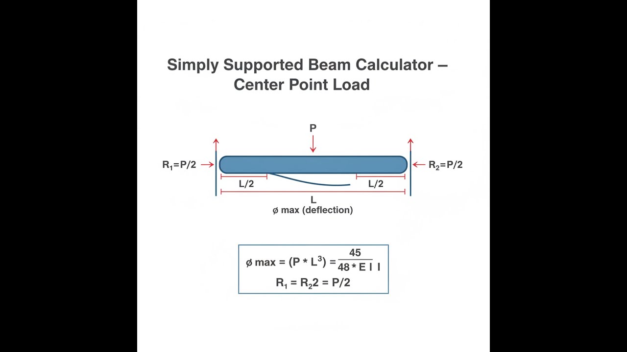
Here, a simply supported beam sits on two supports, free to rotate at both ends, and you apply a single force right at the midpoint. This setup is basic but crops up everywhere. The calculator outputs exactly how much it bends and what sort of forces you’ll get inside the beam.
Simple Explanation
Picture a diving board on two stands, with someone standing directly in the center. Their weight pushes down midspan as a point load, and the board sags — that’s deflection. The board’s stiffness and span control how much it flexes. This tool tells you how far things will bend, before you cut metal or wood.
📐 Browse all 1000+ Interactive Calculators
Simply Supported Beam - Center Point Load Diagram

Simply Supported Beam Point Load Calculator
How to Use This Calculator
This calculator is intended for education, concept evaluation, and preliminary design. Results are based on the equations and assumptions described on this page, but cannot account for every real-world load case, tolerance, material property, environmental condition, installation detail, safety factor, code, or regulatory requirement. Verify all inputs, assumptions, units, and results independently before selecting components or using the result in a real application. Safety-critical, structural, medical, lifting, transportation, or regulated applications must be reviewed by a qualified engineer.
Questions about this calculator or found an error? Message our engineering team.
- Pick Metric (SI) or Imperial (US) at the top.
- Put in the beam length (L), the center load (P), elastic modulus (E), and moment of inertia (I).
- If you want to see what a sample calculation looks like, hit "Try Example."
- Press Calculate. Results appear right below.
Simply Supported Beam interactive visualizer
Watch how beam deflection, moment, and shear forces change as you adjust the point load, beam length, and material properties. Visualize the critical relationships that determine whether your beam design will succeed or fail.
MAX DEFLECTION
0.25 mm
MAX MOMENT
2500 N⋅m
MAX SHEAR
2500 N
FIRGELLI Automations — Interactive Engineering Calculators
Mathematical Equations
For a simply supported beam and a load at the center, you use these standard equations for deflection, moment, and shear:
The simply supported beam point load calculator uses these fundamental structural analysis equations:
Maximum Deflection
δ = PL³ / (48EI)
Maximum Bending Moment
M = PL / 4
Maximum Shear Force
V = P / 2
Where:
- δ = Maximum deflection at beam center
- P = Applied point load
- L = Beam length
- E = Elastic modulus of beam material
- I = Second moment of area (moment of inertia)
- M = Maximum bending moment (occurs at center)
- V = Maximum shear force (occurs at supports)
Simple Example
A steel beam spans 2 m with a 5000 N load at the center. E = 200 GPa, I = 8.33 × 10⁻⁶ m⁴.
- Maximum deflection: δ = (5000 × 2³) / (48 × 200×10⁹ × 8.33×10⁻⁶) = 0.250 mm
- Maximum moment: M = (5000 × 2) / 4 = 2500 N⋅m
- Maximum shear: V = 5000 / 2 = 2500 N
Complete Technical Guide to Simply Supported Beam Analysis
If you're doing real-world engineering, you’ll regularly deal with beams under center loads. Machines, buildings, and automation setups use this model a lot — it’s basic, but not always forgiving if you don’t get your numbers right.
Fundamental Principles of Beam Deflection
When you stick a point load in the center, the beam bends and develops internal stresses across its depth — compression on one side, tension on the other. The calculator just automates these classic mechanical formulas, so you can get results quickly.
Take a close look at the formula δ = PL³/(48EI). Beam length (L) is by far the most critical variable: deflection grows by the cube of the length. Double your span and the deflection goes up eight-fold. If you’re struggling with sag, shortening the span does a lot more than bulking up the cross-section or material.
Material Properties and Cross-Sectional Design
Elastic modulus (E) measures how naturally stiff a material is. For context:
- Steel: 200 GPa (29,000 ksi)
- Aluminum: 70 GPa (10,200 ksi)
- Concrete: 30 GPa (4,350 ksi)
- Wood: 12 GPa (1,740 ksi)
The moment of inertia (I) depends entirely on the cross-section. For a rectangle, it's I = bh³/12 (b = width, h = height), which is why tall skinny beams deflect a lot less than short wide ones. Height is far more effective than width for controlling deflection.
Practical Applications in Engineering
This type of loading shows up everywhere. Some typical cases: floor beams under heavy equipment, bridges carrying trucks, or machine frames where an actuator drives a load smack in the middle. For example, anywhere FIRGELLI linear actuators push or lift, you’re often dealing with a center point load. Getting the deflection right keeps the structure reliable and motion accurate.
Take a setup lifting a 500 kg payload with a linear actuator at the middle of a 2-meter steel beam. Use the calculator to see if deflection and stresses stay within limits that suit both safety and performance.
Worked Example: Industrial Conveyor Support
Let’s walk through a practical job. Say you’ve got a conveyor supported by a beam spanning 1.5 m, needing to hold a 1000 N concentrated load at the midpoint (rectangular steel cross-section: 50mm × 100mm).
Given parameters:
- Point load (P) = 1000 N
- Beam length (L) = 1.5 m
- Elastic modulus (E) = 200 × 10⁹ Pa
- Moment of inertia (I) = (0.05 × 0.1³)/12 = 4.17 × 10⁻⁶ m⁴
Calculations:
Maximum deflection: δ = (1000 × 1.5³)/(48 × 200×10⁹ × 4.17×10⁻⁶) = 0.844 mm
Maximum moment: M = (1000 × 1.5)/4 = 375 N⋅m
Maximum shear: V = 1000/2 = 500 N
With less than 1 mm of deflection, the design might be fine for many jobs, but always check actual stresses and consider things like shock or repeated loading if that matters to your case.
Design Considerations and Safety Factors
Real projects deal with more than just the basic equations. Unexpected loads, repeated cycles, actual material variation, and how precisely things are built all matter. Structural beams in buildings are usually limited to deflection of L/240 to L/360. Machines needing precise motion call for even stiffer designs (L/1000 or tighter).
Temperature shifts can mess with actual deflection, both by changing the stiffness (E) and making the beam expand or contract. If your linear actuator setup is in an environment with wide temperature swings, factor this in early.
Advanced Analysis Considerations
The formulas here cover the scenarios that crop up 90% of the time, but you’ll hit limits if you have non-linear materials, are dealing with heavy loads on short/thick beams (low span/depth ratios), or if shock and vibration are major concerns. Then you may need more detailed models or finite element software.
For slender beams (span more than five times the height), ignoring shear in deflection is usually fine. For short, deep beams, shear starts to matter, and the simple formulas might under-predict sag.
Integration with Modern Design Tools
While modern CAD and FEA tools can model beams in detail, a quick hand or calculator check is the fastest way to avoid mistakes. Before trusting computer output, a manual spot-check using formulas like these is basic engineering practice. In automation or actuator design, deflection controls accuracy — and too much sag can’t be fixed by firmware. Quick checks like these save time and catch problems early.
Frequently Asked Questions
📐 Browse all 1000+ Interactive Calculators →
About the Author
Robbie Dickson
Chief Engineer & Founder, FIRGELLI Automations
Robbie Dickson brings over two decades of engineering expertise to FIRGELLI Automations. With a distinguished career at Rolls-Royce, BMW, and Ford, he has deep expertise in mechanical systems, actuator technology, and precision engineering.
🔗 Related Engineering Calculators
More related engineering calculators:
- Simply Supported Beam Calculator Uniform Load
- Cantilever Beam Calculator Point Load At Free End
- Fixed Fixed Beam Calculator Uniform and Point Loads
- Cantilever Beam Calculator Uniform Distributed Load
- Beam Load Calculator Max Load for Given Beam
- Overhanging Beam Calculator Single Overhang
- Column Buckling Calculator Euler Critical Load
- Ratchet Mechanism Calculator Tooth Load and Size
- Circlip and Retaining Ring Load Calculator
- Center of Mass Multi Component Assembly Calculator
Browse all engineering calculators →
Video Walkthrough - How to Use This Calculator
Need to implement these calculations?
Explore the precision-engineered motion control solutions used by top engineers.


