Designing a power supply filter, building an energy storage bank, or sizing a DC bus for a motor drive all share the same problem: you need to know exactly how much capacitance your parallel combination delivers — and what that means for charge, energy, and transient current. Use this Parallel Capacitor Interactive Calculator to calculate equivalent capacitance, individual charge distributions, total stored energy, and charging current using capacitor values, applied voltage, series resistance, and time. Getting this right matters in industrial VFDs, photographic flash systems, and audio amplifier output stages where undersized or miscalculated capacitor banks cause real failures. This page includes the governing formulas, a full worked motor drive example, plain-English theory, and an FAQ covering ESR, tolerances, and voltage ratings.
What is a parallel capacitor circuit?
A parallel capacitor circuit connects two or more capacitors side by side across the same two voltage nodes. The total capacitance increases — it equals the simple sum of all individual capacitor values.
Simple Explanation
Think of capacitors as buckets that hold electrical charge. Connecting them in parallel is like placing buckets side by side under the same tap — every bucket fills to the same level (voltage), and your total storage is just all the bucket sizes added together. The more capacitors you add in parallel, the more total charge and energy the bank can hold.
📐 Browse all 1000+ Interactive Calculators
How to Use This Calculator
- Select your Calculation Mode from the dropdown — options include equivalent capacitance, charge, energy, voltage, individual capacitance, and charging current.
- Enter the capacitance values for C₁, C₂, and C₃ in microfarads (μF), and enter applied voltage, resistance, or time fields as they appear for your chosen mode.
- Use the Try Example button to load a pre-built set of values if you want to see the calculator in action first.
- Click Calculate to see your result.
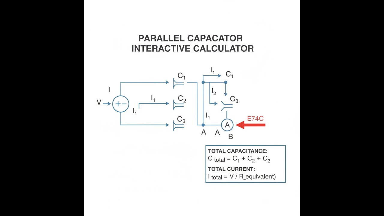
Circuit Diagram

Interactive Calculator
Parallel Capacitor Interactive Visualizer
Watch how capacitors in parallel share charge and combine their capacitance values. Adjust individual capacitor values and voltage to see real-time charge distribution, equivalent capacitance, and energy storage calculations.
EQUIVALENT CAPACITANCE
110 μF
TOTAL CHARGE
1320 μC
TOTAL ENERGY
7.92 mJ
FIRGELLI Automations — Interactive Engineering Calculators
Governing Equations
Use the formula below to calculate equivalent capacitance for capacitors in parallel.
Equivalent Capacitance (Parallel):
Ceq = C1 + C2 + C3 + ... + Cn
Charge on Individual Capacitor:
Qi = Ci × V
Total Charge:
Qtotal = Q1 + Q2 + Q3 + ... + Qn
Total Energy Stored:
E = ½ Ceq V2
Charging Current (RC Circuit):
I(t) = (V / R) × e-t/τ
where τ = R × Ceq
Variable Definitions:
- Ceq = Equivalent capacitance (μF)
- Ci = Individual capacitance of capacitor i (μF)
- Qi = Charge stored on capacitor i (μC)
- V = Applied voltage across parallel combination (V)
- E = Total energy stored (mJ)
- I(t) = Current at time t (mA)
- R = Series resistance (Ω)
- τ = Time constant (ms)
- t = Time (ms)
Simple Example
Three capacitors — 10 μF, 20 μF, and 30 μF — connected in parallel across a 12 V supply:
Ceq = 10 + 20 + 30 = 60 μF
Total charge: Q = 60 μF × 12 V = 720 μC
Total energy: E = ½ × 60 μF × 12² = 4.32 mJ
Theory & Practical Applications
Fundamental Principles of Parallel Capacitance
When capacitors connect in parallel, they share common voltage terminals while maintaining independent charge storage. This configuration fundamentally differs from series arrangements because each capacitor experiences the full source voltage regardless of its individual capacitance value. The equivalent capacitance equals the arithmetic sum of individual capacitances—a direct consequence of charge conservation and the definition of capacitance as the ratio of stored charge to applied voltage. Industrial power supply designers exploit this additive property to achieve precise capacitance values unavailable from standard component catalogs.
The physical interpretation becomes clearer through the plate area analogy: connecting capacitors in parallel effectively increases the total plate area exposed to the electric field, directly proportional to capacitance. For a parallel-plate capacitor with C = ε₀εᵣA/d, adding parallel capacitors increases the effective area A while maintaining constant separation d and dielectric properties. This explains why parallel configurations always increase total capacitance, unlike series arrangements where reciprocal addition reduces the equivalent value.
Charge Distribution and Current Sharing
Each capacitor in a parallel bank stores charge proportional to its capacitance value, with Qi = CiV. A critical engineering insight emerges here: during transient charging, capacitors with larger capacitance draw proportionally higher instantaneous currents because dQ/dt = C(dV/dt). For a 10 μF capacitor charged at 1000 V/s, the instantaneous current reaches 10 mA, while a parallel 47 μF unit simultaneously draws 47 mA. This unequal current sharing has profound implications for PCB trace design and connector current ratings in high-power applications.
The total charge stored across the parallel combination equals Qtotal = CeqV = (C1 + C2 + ... + Cn)V, verifying that charge contributions sum algebraically. This relationship holds regardless of capacitor technology—ceramic, electrolytic, film, or supercapacitor—provided all units operate within their voltage ratings. In photographic flash circuits using multiple electrolytics totaling 2400 μF charged to 330 V, the total stored charge reaches 792 millicoulombs, delivering the rapid energy release required for xenon tube ignition.
Energy Storage and Power Density
The energy stored in a parallel capacitor bank follows E = ½CeqV², demonstrating quadratic dependence on voltage. Doubling the voltage quadruples stored energy—a fundamental relationship exploited in pulsed power systems and electromagnetic launchers. For industrial motor drives using 8200 μF bus capacitors at 800 VDC, stored energy reaches 2.6 kJ, providing the instantaneous power required during acceleration transients while buffering supply voltage variations.
A non-obvious consequence of parallel connection concerns energy distribution among capacitors: despite unequal charge storage, each capacitor stores energy proportional to its capacitance because Ei = ½CiV². A 100 μF capacitor stores exactly ten times the energy of a 10 μF unit at identical voltage. This proportional energy distribution ensures thermal loading scales with capacitance value during repetitive charge-discharge cycling, critical for reliability analysis in power electronics where ripple current heating determines component lifespan.
Transient Response and RC Time Constants
When charging parallel capacitors through series resistance, the time constant τ = RCeq governs response speed. The equivalent capacitance directly multiplies the resistance value, making parallel banks inherently slower to charge than individual capacitors. A 100 Ω resistor charging three parallel capacitors (10 μF + 22 μF + 47 μF = 79 μF) produces τ = 7.9 ms, requiring approximately 39.5 ms (5τ) to reach 99% of final voltage.
The charging current follows I(t) = (V/R)e-t/τ, with maximum current I₀ = V/R occurring at t = 0 when capacitors behave as short circuits. For a 24 V source with 100 Ω resistance, initial current peaks at 240 mA before exponentially decaying. This inrush current phenomenon drives design requirements for current-limiting circuits in switched-mode power supplies, where uncontrolled inrush can trigger overcurrent protection or damage rectifier diodes. Advanced designs incorporate negative temperature coefficient (NTC) thermistors that limit cold-start current while presenting low resistance during steady-state operation.
Real-World Engineering Applications
Industrial automation systems deploy parallel capacitor banks for DC bus stabilization in variable frequency drives (VFDs), where motor load transients cause voltage fluctuations. A typical 15 kW VFD operating at 540 VDC employs 3000-4500 μF of parallel electrolytic capacitance, providing energy buffering during regenerative braking events when mechanical energy converts back to electrical form. The capacitor bank absorbs regenerated power temporarily, preventing overvoltage trips while the braking resistor dissipates excess energy.
Photographic flash equipment demonstrates parallel capacitance in portable high-energy systems. Professional studio strobes use multiple 450 V electrolytic capacitors totaling 2000-6000 μF, storing 200-800 joules per flash. The parallel configuration enables rapid discharge through the flash tube (typical pulse duration 1-5 ms) while distributing current stress across multiple components, enhancing reliability compared to single large-value alternatives. Recycle time between flashes depends on both charging circuit current capability and total capacitance, with professional units achieving sub-2-second recycling through optimized parallel arrangements.
Audio power amplifier designs incorporate parallel film capacitors in the output stage to minimize equivalent series resistance (ESR) and equivalent series inductance (ESL). A high-fidelity amplifier may parallel ten 10 μF polypropylene capacitors rather than using a single 100 μF unit because ESR scales inversely with the number of parallel units (ESReq = ESRindividual/n). This dramatically reduces power dissipation during high-frequency signal reproduction, where reactive current circulation between amplifier and speaker generates I²R losses proportional to ESR.
Practical Design Considerations and Edge Cases
Component tolerance stacking in parallel banks requires statistical analysis to predict actual equivalent capacitance. Three 100 μF capacitors with ±20% tolerance (80-120 μF range) produce equivalent capacitance spanning 240-360 μF—a 50% variation from the nominal 300 μF target. Mission-critical applications specify tighter tolerances (±5% or ±10%) or implement active capacitance measurement during production to verify performance.
Voltage derating becomes critical in parallel banks because all capacitors experience identical voltage stress. Electrolytic capacitors typically require 50% derating for long-term reliability; a 450 V-rated capacitor should operate below 225 V continuously. This derating accounts for aging effects where electrolyte evaporation and oxide layer degradation progressively reduce capacitance and increase ESR over 5000-10000 hour lifespans at elevated temperatures.
Parasitic effects at high frequencies transform ideal capacitors into complex RLC networks. The parallel combination of lead inductance (typically 10-20 nH per component) creates parallel resonant frequencies where impedance peaks rather than continuing to decrease. For three parallel 47 μF ceramic capacitors with 15 nH lead inductance each, the effective lead inductance becomes 5 nH (Leq = L/n), shifting resonance to higher frequency but introducing potential impedance notches that destabilize feedback loops in switching regulators. Advanced PCB layouts minimize lead length and employ low-ESL packages (0805, 1210) with multiple vias to reduce parasitic inductance below 2 nH.
Worked Example: Motor Drive Bus Capacitor Selection
Problem Statement: Design a DC bus capacitor bank for a 22 kW three-phase VFD operating from 480 VAC input (nominal DC bus voltage 678 VDC after rectification). The motor exhibits worst-case regeneration of 8.3 kW for 150 ms during emergency braking. The bus voltage must remain below 750 VDC (110% of nominal) without engaging the braking resistor. Pre-charge circuitry limits inrush current to 5 A through a 150 Ω resistor. Select appropriate capacitor values, voltage ratings, and verify charging characteristics.
Solution:
Step 1 - Calculate Required Capacitance:
Energy absorbed during regeneration: E = Power × Time = 8300 W × 0.150 s = 1245 J
Allowable voltage rise: ΔV = 750 V - 678 V = 72 V
Energy stored in capacitor: E = ½C(V₂² - V₁²)
1245 = ½C(750² - 678²)
1245 = ½C(562500 - 459684)
1245 = ½C(102816)
C = (2 × 1245) / 102816 = 0.0242 F = 24,200 μF
Step 2 - Select Standard Capacitor Configuration:
Use six parallel 450 V 4700 μF electrolytic capacitors (industry standard for VFD applications)
Total capacitance: Ceq = 6 × 4700 μF = 28,200 μF (16.5% margin above minimum)
Voltage rating check: 450 V rated, operating at 678 V max = 151% stress
This exceeds safe operating voltage—requires 800 V or 1000 V rated capacitors
Revised selection: six parallel 800 V 3900 μF capacitors
Ceq = 6 × 3900 μF = 23,400 μF (still within 3.3% of required value)
Voltage stress: 678 V / 800 V = 84.8% (acceptable with 15.2% margin)
Step 3 - Verify Pre-charge Characteristics:
Time constant: τ = R × Ceq = 150 Ω × 0.0234 F = 3.51 seconds
Time to reach 95% of 678 V: t = 3τ = 10.53 seconds
Initial inrush current: I₀ = 678 V / 150 Ω = 4.52 A (below 5 A limit ✓)
Current at t = 5 s: I(5) = 4.52 A × e^(-5/3.51) = 4.52 A × e^(-1.425) = 4.52 A × 0.240 = 1.08 A
Voltage at t = 5 s: V(5) = 678 V × (1 - e^(-5/3.51)) = 678 V × (1 - 0.240) = 678 V × 0.760 = 515 V
Step 4 - Calculate Energy Storage Verification:
Energy at nominal voltage: Enominal = ½ × 23,400 μF × (678 V)² = ½ × 0.0234 F × 459,684 V² = 5379 J
Energy at maximum voltage: Emax = ½ × 23,400 μF × (750 V)² = ½ × 0.0234 F × 562,500 V² = 6581 J
Energy absorption capacity: ΔE = 6581 J - 5379 J = 1202 J (within 3.5% of 1245 J requirement ✓)
Actual voltage rise during regeneration: V₂² = V₁² + (2E/C) = 459,684 + (2 × 1245 / 0.0234) = 459,684 + 106,410 = 566,094
V₂ = √566,094 = 752 V (2 V over target—acceptable given safety margin in brake resistor threshold)
Conclusion: Six parallel 800 V 3900 μF electrolytic capacitors provide adequate energy storage margin with appropriate voltage derating. Pre-charge time of 10.5 seconds falls within typical VFD startup sequences. The 1.08 A residual current at 5 seconds allows safe contactor closure without arc damage. Total component cost and board space remain reasonable for a 22 kW drive application.
Frequently Asked Questions
Free Engineering Calculators
Explore our complete library of free engineering and physics calculators.
Browse All Calculators →🔗 Explore More Free Engineering Calculators
- LED Resistor Calculator — Current Limiting
- Capacitor Charge Discharge Calculator — RC Circuit
- Resistor Color Code Calculator
- I2C Pull-Up Resistor Calculator
- Current Divider Calculator
- Capacitors In Series Calculator
- Parallel Resistor Calculator
- Voltage Divider Calculator — Output Voltage from Two Resistors
- Voltage Divider Calculator
- Power Factor Calculator and Correction
About the Author
Robbie Dickson — Chief Engineer & Founder, FIRGELLI Automations
Robbie Dickson brings over two decades of engineering expertise to FIRGELLI Automations. With a distinguished career at Rolls-Royce, BMW, and Ford, he has deep expertise in mechanical systems, actuator technology, and precision engineering.
Need to implement these calculations?
Explore the precision-engineered motion control solutions used by top engineers.


