Grouped piles don't behave like isolated ones — their stress zones overlap in the soil, and that interaction cuts into total load capacity in ways that catch engineers off guard. Use this Pile Group Efficiency Calculator to calculate group efficiency factors, group capacity, and settlement amplification ratios using pile diameter, center-to-center spacing, and row/column configuration. It matters in bridge foundations, high-rise building foundations, and industrial structures where getting pile spacing wrong wastes money or compromises safety. This page covers the governing formulas, a worked design example, method comparisons, and a full FAQ.
What is Pile Group Efficiency?
Pile group efficiency is a number between 0 and 1 that tells you how much of a pile group's theoretical combined capacity you can actually use. A group of 9 piles with efficiency of 0.70 carries 70% of what those 9 piles could carry if each one were standing alone.
Simple Explanation
Think of each pile as pushing outward through the soil around it — like pressing your fingers into sand. If you press all your fingers close together, the sand between them gets compressed from all sides at once and can't take any more load. Spread your fingers wider and each one works independently, carrying its full share. Pile group efficiency captures exactly that effect — how much the piles are "stepping on each other's toes" in the soil below.
📐 Browse all 1000+ Interactive Calculators
Visual Diagram

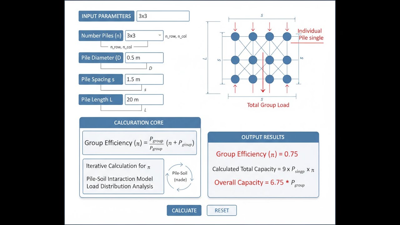
Pile Group Efficiency Interactive Calculator
How to Use This Calculator
- Select your calculation mode from the dropdown — choose Converse-Labarre efficiency, group capacity, settlement ratio, spacing optimization, Los Angeles method, or Feld's rule.
- Enter the pile geometry inputs shown for your selected mode: pile diameter, center-to-center spacing, number of rows, number of columns, and total number of piles as required.
- If calculating group capacity, also enter the single pile allowable capacity (kN) and the efficiency factor (η).
- Click Calculate to see your result.
Simple Example
A 3×3 group of 9 piles, each 0.4 m diameter, at 1.2 m center-to-center spacing:
- Spacing/diameter ratio: 1.2 / 0.4 = 3.0
- θ = arctan(0.4 / 1.2) = 18.43°
- Converse-Labarre efficiency (η) ≈ 0.67
- If single pile capacity = 450 kN → Group capacity = 0.67 × 9 × 450 = 2,722 kN
Pile Group Efficiency Interactive Visualizer
See how pile spacing affects group efficiency and stress overlap zones in real-time. Adjust spacing and group configuration to understand load capacity reduction from pile interaction effects.
GROUP EFFICIENCY
0.67
OVERLAP INDEX
18.4°
CAPACITY LOSS
33%
FIRGELLI Automations — Interactive Engineering Calculators
Governing Equations
Use the formula below to calculate pile group efficiency.
Converse-Labarre Formula
η = 1 - [θ / 90°] × [(m-1)n + (n-1)m + √2(m-1)(n-1)] / (mn)
Where:
- η = group efficiency factor (dimensionless, 0 to 1)
- θ = arctan(d/s) in degrees
- d = pile diameter (m)
- s = center-to-center pile spacing (m)
- m = number of rows in pile group
- n = number of columns in pile group
Group Capacity
Use the formula below to calculate group capacity.
Qg = η × n × Qs
Where:
- Qg = total allowable capacity of pile group (kN)
- η = group efficiency factor
- n = total number of piles in group
- Qs = allowable capacity of single pile (kN)
Los Angeles Method
Use the formula below to calculate efficiency using the Los Angeles method.
η = 1 / [1 + (d / (π × s)) × (n - 1)]
Application: Empirical formula particularly suited for friction piles in sandy soils. Tends to be more conservative than Converse-Labarre for closely spaced piles.
Feld's Rule (Block Failure Method)
Use the formula below to calculate efficiency using Feld's rule.
η = Pg / (n × π × d)
Where:
- Pg = perimeter of pile group block (m)
- n = number of piles
- d = pile diameter (m)
Application: Used when piles are closely spaced and may fail as a block. Particularly relevant for cohesive soils where undrained shear strength governs.
Settlement Amplification
Use the formula below to calculate settlement amplification ratio.
Sg / Ss = √n × (Bg / (n × d))
Where:
- Sg = settlement of pile group (mm)
- Ss = settlement of single pile under same load per pile (mm)
- Bg = width of pile group (m)
- n = number of piles
- d = pile diameter (m)
Theory & Engineering Applications
Fundamentals of Pile Group Behavior
When piles are installed in groups, their individual stress bulbs overlap within the supporting soil mass, creating a complex three-dimensional stress distribution that fundamentally differs from isolated pile behavior. This interaction phenomenon means that the total capacity of a pile group is invariably less than the arithmetic sum of individual pile capacities. The group efficiency factor (η) quantifies this reduction, typically ranging from 0.5 to 0.9 depending on pile spacing, soil type, and installation method. For friction piles in cohesionless soils, efficiency decreases more gradually with reduced spacing compared to end-bearing piles or piles in cohesive soils, where block failure mechanisms can dominate when spacing falls below critical thresholds.
The stress overlap extends both laterally and vertically, with effects measurable at depths significantly exceeding the pile group dimensions. In clayey soils, the zone of influence can extend 1.5 to 2 times the group width below the pile tips, while in sandy soils, the influence zone is typically 1 to 1.5 times the group width. This deep stress transmission is why pile groups exhibit settlement characteristics fundamentally different from single piles—a phenomenon captured by the settlement amplification ratio, which can reach values of 3 to 5 for large groups in compressible soil profiles.
The Converse-Labarre Formula: Development and Limitations
The Converse-Labarre formula, developed in the early 20th century, remains the most widely applied efficiency calculation method due to its relative simplicity and reasonable accuracy for typical configurations. The formula incorporates geometric parameters—pile spacing, diameter, and group arrangement—into an efficiency factor based on the assumption that stress overlap zones are approximately conical with apex angles related to the spacing-to-diameter ratio. The arctan(d/s) term captures this geometric relationship, while the bracketed expression accounts for the number of interaction paths between adjacent piles in rows, columns, and diagonals.
A critical, often overlooked limitation of the Converse-Labarre method is its assumption of uniform soil properties and linear pile behavior. In stratified soil profiles with interbedded soft and stiff layers, the actual efficiency can deviate by 15-25% from calculated values because stress distribution becomes highly non-uniform. Additionally, the formula does not account for construction sequence effects: piles driven in the center of a group compact the soil differently than perimeter piles, creating spatial variations in capacity that the formula cannot capture. For large groups (more than 25 piles), these edge effects become significant, and the formula tends to underestimate efficiency for perimeter piles while overestimating it for interior piles.
Alternative Efficiency Methods and Their Applications
The Los Angeles method provides a simpler, more conservative approach particularly suited for preliminary design of friction piles in granular soils. Its empirical basis stems from field observations of driven pile groups in southern California alluvial deposits, where the formula showed good correlation with load test results for spacing ratios between 2.5 and 5.0. However, this method lacks sensitivity to group geometry (rectangular versus square arrangements) and should not be applied to end-bearing piles or groups in cohesive soils, where its predictions can be unconservative by 20-30%.
Feld's rule represents a fundamentally different approach based on block failure mechanics. When piles are spaced closer than 2.5 diameters in cohesive soils, the group may fail as a coherent block along a perimeter surface rather than through individual pile mechanisms. In this scenario, the relevant capacity is governed by the shear strength mobilized along the group perimeter and base, making the perimeter-to-pile-diameter ratio the critical parameter. Feld's rule is essential for closely spaced pile groups in soft clays (undrained shear strength less than 50 kPa) but becomes increasingly irrelevant as spacing increases beyond 3 diameters, where individual pile behavior dominates.
Settlement Considerations in Pile Group Design
The settlement amplification phenomenon represents one of the most significant challenges in pile group foundation design. While individual piles may settle only 10-15 mm under working loads, a 3×3 group of identical piles carrying the same load per pile can settle 30-50 mm due to deep stress accumulation in compressible layers below the pile tips. This counterintuitive behavior occurs because the group's stress bulb is much wider and extends deeper than that of a single pile, mobilizing compression in soil strata that individual piles barely influence.
The settlement ratio (Sg/Ss) provides a multiplier for estimating group settlement from single pile settlement data, but its application requires careful consideration of soil compressibility profiles. In profiles with thick, highly compressible layers at depth (such as estuarine deposits or buried organic layers), the settlement ratio can exceed predicted values by 50-100% because conventional formulas assume semi-infinite homogeneous soil. For critical projects, settlement should be calculated using rigorous methods such as 3D finite element analysis or by treating the group as an equivalent pier with dimensions equal to the group envelope, then applying traditional consolidation theory using stress distributions from Boussinesq or Westergaard solutions.
Simple Example
A 4×4 pile group (16 piles), 400 mm diameter, at 1.6 m spacing, each pile rated at 380 kN:
- θ = arctan(0.4 / 1.6) = 14.04°
- Converse-Labarre η = 0.642
- Group capacity = 0.642 × 16 × 380 = 3,903 kN
- Settlement ratio = 4 × (4.8 / 6.4) = 3.0 — check serviceability separately
Worked Example: Industrial Warehouse Foundation Design
Consider a design scenario for a precast concrete warehouse with column loads of 3,200 kN spaced at 9 m intervals. Site investigation reveals 8.5 m of medium-dense silty sand (SPT N-value averaging 18) overlying dense glacial till. Individual driven concrete piles (400 mm square section) have been determined to have an allowable capacity of 380 kN based on dynamic formula and pile driving analyzer results. Design a pile group foundation for a typical interior column.
Step 1: Initial Pile Count Estimation
Assuming an efficiency factor of 0.70 (typical for sand), preliminary pile count:
n = 3,200 kN / (380 kN × 0.70) = 12.03 piles → Use 12 piles
Step 2: Group Arrangement
Select a 3×4 rectangular configuration (3 rows, 4 columns) to provide symmetry and fit within column tributary area.
Try spacing s = 1.4 m (3.5 diameters, within optimal range of 3-6d)
Step 3: Converse-Labarre Efficiency Calculation
θ = arctan(d/s) = arctan(0.4/1.4) = arctan(0.2857) = 15.95°
m = 3 rows, n = 4 columns, total piles = 12
Interaction term = [(m-1)n + (n-1)m + √2(m-1)(n-1)] / (mn)
= [(3-1)×4 + (4-1)×3 + √2(3-1)(4-1)] / (3×4)
= [8 + 9 + 1.414×2×3] / 12
= [8 + 9 + 8.485] / 12 = 25.485 / 12 = 2.124
η = 1 - (15.95/90) × 2.124 = 1 - 0.1772 × 2.124 = 1 - 0.376 = 0.624
Step 4: Group Capacity Verification
Qg = η × n × Qs = 0.624 × 12 × 380 kN = 2,845 kN
This is less than required 3,200 kN. Need to revise.
Step 5: Design Iteration
Option A: Increase to 16 piles (4×4 arrangement):
Same spacing (1.4 m), recalculate efficiency:
Interaction term for 4×4 = [(4-1)×4 + (4-1)×4 + √2(4-1)(4-1)] / 16
= [12 + 12 + 1.414×3×3] / 16 = [24 + 12.73] / 16 = 2.296
η = 1 - 0.1772 × 2.296 = 1 - 0.407 = 0.593
Qg = 0.593 × 16 × 380 = 3,603 kN ✓ Adequate with 12.6% margin
Step 6: Settlement Estimate
Group width Bg = 3 × 1.4 m = 4.2 m
Settlement ratio = √16 × (4.2 / (16 × 0.4)) = 4 × (4.2 / 6.4) = 4 × 0.656 = 2.62
If single pile settlement = 12 mm (from load test), group settlement ≈ 2.62 × 12 = 31 mm
This exceeds typical tolerance of 25 mm for precast structures.
Step 7: Final Optimization
Increase spacing to 1.6 m (4 diameters):
θ = arctan(0.4/1.6) = 14.04°
η = 1 - (14.04/90) × 2.296 = 1 - 0.358 = 0.642
Qg = 0.642 × 16 × 380 = 3,904 kN ✓
Bg = 4.8 m
Settlement ratio = 4 × (4.8/6.4) = 3.0
Group settlement ≈ 36 mm (still marginal)
Conclusion: Final design uses 16 piles (4×4) at 1.6 m spacing, providing adequate capacity with η = 0.642. Settlement concerns require either: (1) preloading the foundation area to pre-compress the sand layer, (2) specifying pile installation sequence to maximize densification effects, or (3) accepting slightly higher settlements with provision for differential settlement accommodation in the structural design (jacking pockets at column bases). This example illustrates how efficiency calculations directly influence both pile count and constructability considerations.
Design Standards and Factor of Safety Considerations
International building codes prescribe varying approaches to pile group design factors of safety. Eurocode 7 requires characteristic capacity divided by partial factors (typically 1.4 for driven piles) with additional model factors if advanced calculation methods deviate from established procedures. ASCE 7 in North America traditionally applies a global factor of safety of 2.5 to 3.0 to ultimate capacity, though LRFD approaches now use resistance factors of 0.50-0.65 depending on installation method and verification testing. The efficiency factor is applied after determining individual pile capacity but before applying factors of safety, meaning a low efficiency directly reduces the factored capacity denominator.
A frequently misunderstood aspect involves whether to apply efficiency to ultimate or allowable capacities. Best practice applies efficiency to individual pile ultimate capacity, then applies appropriate factors of safety to obtain group allowable capacity. Applying efficiency to already-factored allowable capacities results in excessive conservatism (effectively applying efficiency twice). For critical structures or unusual soil conditions, pile load tests on groups of 2-3 piles spaced at design values provide empirical efficiency data far superior to formula predictions, justifying the additional cost for projects with more than 50 piles.
Installation Effects and Construction Considerations
Pile installation sequence profoundly affects final group efficiency, particularly for displacement piles in cohesionless soils. Driving piles from the center outward compacts the soil and increases its density, potentially improving efficiency by 10-20% compared to perimeter-inward installation. However, this advantage must be weighed against the risk of heave-induced tensile stresses in previously installed piles and the practical difficulty of equipment access. For projects in soft clays, the opposite strategy (perimeter-inward) minimizes remolding effects and pore pressure buildup that can reduce capacity by 30-40% if insufficient setup time is allowed between installations.
Bored pile groups present fundamentally different challenges: no installation compaction benefits soil, and drilling fluid infiltration can reduce lateral earth pressure, lowering side friction efficiency. For bored pile groups, efficiency predictions from driven pile formulas should be reduced by an additional factor of 0.85-0.90 unless site-specific testing demonstrates otherwise. The selection between driven and bored piles for a given project involves complex tradeoffs between installation cost, noise restrictions, soil disturbance, and ultimate efficiency—factors that extend beyond simple capacity calculations to encompass entire project delivery strategies. More detailed guidance on these considerations is available through engineering resources including the comprehensive calculator library.
Practical Applications
Scenario: Bridge Pier Foundation in Riverbed Alluvium
Marcus, a bridge engineer designing a four-span highway crossing, faces the challenge of founding pier P-2 in 14 meters of loose to medium-dense alluvial sand with high groundwater. Each pier must carry 8,500 kN from the superstructure. Individual 500 mm diameter driven steel pipe piles have been load-tested to 620 kN allowable capacity. Using this calculator with a preliminary 4×4 arrangement at 2.0 m spacing (4 diameters), Marcus determines the Converse-Labarre efficiency is 0.68, yielding a group capacity of 6,733 kN—inadequate. He iterates to a 5×4 configuration at 1.8 m spacing, which improves efficiency slightly to 0.64 but increases pile count to 20, providing 7,936 kN. Still short, he opts for a 6×4 arrangement with 24 piles, achieving 9,549 kN group capacity with η = 0.623, providing necessary safety margin while accounting for scour effects. The calculator's settlement ratio of 3.8 alerts him to potential long-term consolidation issues, prompting specification of high-modulus sand backfill around the pile cap to limit differential movements during the bridge's 75-year design life.
Scenario: Residential Tower Foundation Optimization
Jennifer, a geotechnical consultant working on a 22-story residential tower in coastal soft clay, needs to optimize foundation costs while meeting stringent settlement criteria of 40 mm total and 15 mm differential. The architectural layout requires 18 column positions, each carrying 2,100 kN. Initial design calls for 350 mm square precast concrete piles driven to bedrock at 22 m depth, with individual capacity of 285 kN. Using the calculator's capacity mode, Jennifer determines that 9-pile groups (3×3) at 1.4 m spacing yield efficiency of 0.71, providing 1,820 kN per group—insufficient. Rather than simply adding piles, she uses the spacing optimization mode to explore whether wider spacing could improve efficiency enough to reduce pile count. Testing 1.8 m spacing (5.14 diameters) shows efficiency improving to 0.78, allowing 9 piles to carry 2,000 kN—still marginal. She settles on a 3×4 arrangement (12 piles) at 1.6 m spacing, achieving 2,670 kN capacity per column with acceptable settlement ratio of 2.9. This design saves approximately 108 piles across the project compared to the initial overly conservative estimate, reducing foundation cost by $240,000 while maintaining structural performance requirements and simplifying the site logistics in a constrained urban environment.
Scenario: Retrofitting Existing Structure with Additional Piles
David, a structural engineer tasked with evaluating a 1970s-era warehouse for conversion to heavy manufacturing use, discovers that column loads will increase from 1,200 kN to 2,800 kN due to overhead crane installation and increased storage density. The existing foundations consist of 2×2 pile groups (300 mm diameter driven piles at 1.2 m spacing) that cannot be economically replaced. He proposes adding four additional piles around the perimeter of each existing group, creating a 4×4 configuration with mixed spacing: 1.2 m between original piles and 0.9 m from original to new piles. Using this calculator's Converse-Labarre mode with averaged spacing of 1.05 m (3.5 diameters), he calculates a conservative efficiency of 0.58 for the 16-pile augmented group. However, he recognizes this may be overly conservative because the original 4 piles have already consolidated the soil. He switches to the Los Angeles method, which accounts better for pre-existing compaction, yielding efficiency of 0.63. With individual pile capacity of 180 kN (derated from original design values due to age and potential deterioration), the augmented group provides 1,814 kN. Combined with underpinning the pile cap and adding grade beams to redistribute load, this solution proves 60% less expensive than complete foundation replacement while providing adequate capacity with appropriate safety factors for the industrial conversion.
Frequently Asked Questions
Why does pile group efficiency decrease as spacing decreases? +
Should I use the same efficiency formula for both friction and end-bearing piles? +
How do I account for piles in different soil layers when calculating efficiency? +
What is the relationship between group efficiency and settlement amplification? +
When should I use Converse-Labarre versus Los Angeles versus Feld methods? +
How does pile installation method affect group efficiency calculations? +
Free Engineering Calculators
Explore our complete library of free engineering and physics calculators.
Browse All Calculators →🔗 Explore More Free Engineering Calculators
About the Author
Robbie Dickson — Chief Engineer & Founder, FIRGELLI Automations
Robbie Dickson brings over two decades of engineering expertise to FIRGELLI Automations. With a distinguished career at Rolls-Royce, BMW, and Ford, he has deep expertise in mechanical systems, actuator technology, and precision engineering.
Need to implement these calculations?
Explore the precision-engineered motion control solutions used by top engineers.


