What is an Arduino?
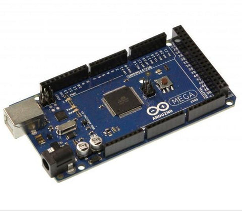
Arduino is an open source electronics prototyping platform based on flexible, easy-to-use hardware and software. It's intended for DIY projects, artists, designers, hobbyists, and anyone interested in creating interactive projects. Arduinos are microcontroller boards that contain everything you need to easily interface with the microcontroller. A microcontroller is like a mini-computer for embedded systems and the type of microcontroller included will depend on the style of Arduino. Arduino ranges from the larger Arduino Mega to the midsize Arduino Uno to the smaller Arduino Pro Mini. The different size boards will provide an increasing number of I/O pins and additional features and the most popular of these boards is the Uno. Arduino also provides an open source free to use IDE to program your microcontrollers. The Arduino IDE uses an easy to understand programming language and due to Arduino’s popularity, you can find many helpful examples online to help you code for your specific application. If this is your first Arduino project, the Arduino kit will provide you with everything you need from jumper cables to sensors to relays and includes Arduino Uno to get you started.

Why Use an Arduino to Control a Linear Actuator?
One of the biggest advantages of using an Arduino, or any microcontroller for that matter, to control a linear actuator is that you have greater control over your linear actuator. Microcontrollers allow you to use more complex inputs from sensors or other devices to control your linear actuator. They allow you to preform real-time calculations to position your actuator in the ideal position or implement timers to automate position changes of your actuators. Microcontrollers can also take in feedback from your actuators to provide more precise position and speed control as well as control more than one actuator at one time. Simply put, microcontrollers provide you with greater control and flexibility and with Arduino’s easy to use design and wide popularity, the level of additional complexity is minimal.
Controlling a Linear Actuator with an Arduino
You won’t be able to directly interface your linear actuator to an Arduino like you can with a switch as the operating voltage of the Arduino is only 5V and has very small current limits. You’ll need to use an intermediate component to control the linear actuator which can be done using either relays or a motor driver.
Relays
As discussed here, relays are electromagnetic switches that are controlled by energizing and de-energizing a coil to open and close the switch. The Arduino can be used to control the relay by energizing and de-energizing the coil using one I/O pin. Depending on the type of relay you use will change how much control you have over your linear actuator, but interfacing with the Arduino is pretty straight forward, just energize the coil with an I/O pin. You’ll need to ensure that the rated voltage of the coil is around the operating voltage of the Arduino (5V) or the Arduino will not be able to energize the coil enough to cause the switch to close.

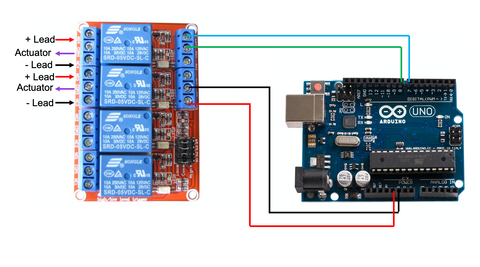
Above is an example of an Arduino interfacing with a two SPDT relay configuration. In this configuration, which is described here, the two relays are used to flip the polarity of the voltage to the linear actuator as well as disconnect the power to the actuator. In the code example is shown below, the Arduino will energize the top relay to extend the actuator for 2 seconds by setting pin 7 to low, then stop the actuator for 2 seconds by de-energizing the top relay by setting both pins to high. To retract the actuator, the Arduino will energize the second relay for 2 seconds by setting pin 8 to low, then stop the actuator for 2 seconds by again setting all the pins to high. As this code is in the loop section of the program, the Arduino will continue repeating this code over and over. Obviously, you could implement a more elegant coding solution for your application, but if you are looking for even more control, you’ll want to use a motor driver.
https://gist.github.com/OMikeGray/6bf644b6cda85bfe8c898ccd44ec6d78
Motor Driver
A motor driver is an integrated circuit design specifically to control DC motors, which drive DC linear actuators. Motor drivers commonly make use of an H-bridge to allow for both direction and speed control. How to exactly connect your Arduino to your motor driver will depend on the exact motor driver but will require at least two I/O pins to do so and one of them will be a PWM signal. PWM or pulse-width modulation is a method of varying a signal between on and off values to effectively supply a lower than operating voltage. The motor driver can then use this signal to adjust the speed at which the motor runs.

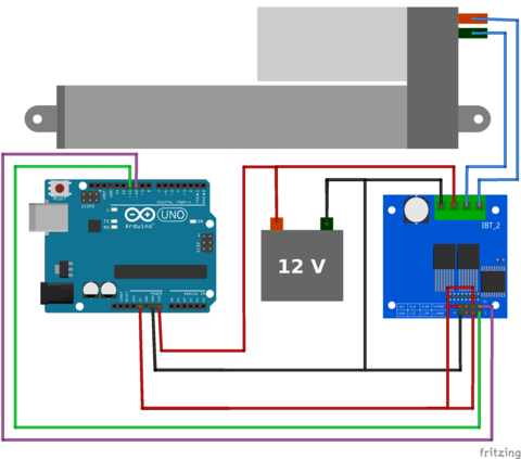
Above is an example of our High Current DC Motor Drive interfaced with an Arduino. For this motor driver, you are required to send two PWM signals, one to extend the actuator and the other to retract. The PWM is given as an unsigned byte meaning it ranges from 0, no voltage, to 255, max voltage (5V), which will be proportional to the speed of the motor. As PWM is not a binary value, we need to use the PWM pins of the Arduino and use the analog write function, as seen in the example below. PWM pins will be indicated on the Arduino with a ~ or simply labelled as PWM pins.
https://gist.github.com/OMikeGray/c4e0196704a4d62db5507ad8297708f4
In the code example above, the Arduino will extend the actuator at full speed for two seconds by sending the motor driver the full 5V out of pin 10 to the LPWM pin on the motor driver. Then the Arduino stops the actuator by not sending any signal to either input pin of the motor driver. The Arduino then retracts the actuator at half speed by sending the motor driver signal that is half on and half off from pin 11 to RPWM pin on the motor driver. Then stops the actuator again. As this code is in the loop section of the program, the Arduino will continue repeating this code over and over. Once again, you could implement a more elegant coding solution that suits your application, especially if you add inputs to control your actuator.
Adding Inputs
Once you can control your actuator with an Arduino, you can then implement inputs to the Arduino for greater automation and control. These inputs can be switches, a wide range of sensors, or even feedback from the actuator itself. As there is a wide range of options for inputs, how to implement them will vary but there are a few general points you should know. If the input provides a binary input, like a switch, you’ll want to make use of the digital pins on the Arduino, which will be labelled on the board or in the datasheet, and make use of the digitalRead() function in the Arduino IDE. If your input device provides an analog signal, you’ll need to make use of the analog pins, which will be labelled on the board or in the datasheet, and make use of the AnalogRead() function.