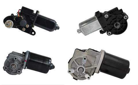
Introduction to DC Gear Motors: Precision Motion Through Mechanical Advantage
In the world of motion control, DC gear motors represent one of the most elegant solutions to a fundamental engineering challenge: how to convert high-speed electrical rotation into powerful, controlled mechanical force. By combining the efficiency of direct current motors with the mechanical advantage of precision gearboxes, these workhorses deliver high torque at low speeds—a combination that makes them indispensable across industries from automotive to robotics.
🎥 Video — Ultimate Guide to DC Gear Motors
Unlike standard DC motors that excel at high speeds but lack the force for demanding applications, DC gear motors leverage gear reduction to multiply torque while proportionally reducing speed. This transformation enables a compact motor to power everything from automotive windshield wipers to TV lifts, from robotic joints to industrial automation systems. For engineers and DIY makers alike, understanding how these motors work—and how to select the right one—is essential for successful project implementation.
This comprehensive guide explores the fundamentals of DC gear motor technology, from the physics of gear ratios to real-world efficiency considerations. We'll examine manufacturing processes, control methods, and application-specific selection criteria, providing you with the technical knowledge to choose and implement DC gear motors confidently. Whether you're designing automated drawer slides, building a custom rotary actuator system, or simply looking to understand these ubiquitous devices better, this guide delivers the engineering insights you need.
What Is a DC Gear Motor and How Does It Work?
A DC gear motor consists of two integrated components working in concert: a DC electric motor and a reduction gearbox. The DC motor serves as the prime mover, converting electrical energy into mechanical rotary motion through electromagnetic induction. When current flows through the motor's windings (the rotor), it creates a magnetic field that interacts with the permanent magnets in the stator, producing continuous rotation. The commutator—a crucial component—switches the current direction through the rotor windings as it rotates, maintaining unidirectional torque.
The gearbox, also known as a gear reducer or reduction gear, transforms the motor's output characteristics through mechanical advantage. High-speed, low-torque rotation from the motor shaft enters the gearbox and passes through a series of intermeshed gears. Each gear stage reduces speed while proportionally increasing torque. The final output shaft rotates significantly slower than the motor shaft but delivers substantially more rotational force.
This speed-torque trade-off is the fundamental principle that makes DC gear motors so versatile. A bare DC motor might spin at 10,000 RPM but produce only minimal torque—insufficient for most practical applications. By adding a gearbox with appropriate reduction, that same motor can output 100 RPM with 100 times the torque (accounting for efficiency losses), making it suitable for powering mechanisms that require substantial force at controlled speeds.
DC Motor Fundamentals
The DC motor component operates on Faraday's law of electromagnetic induction. When voltage is applied across the motor terminals, current flows through the rotor windings, generating a magnetic field. This field interacts with the fixed magnetic field from permanent magnets or field windings in the stator, creating a torque that causes rotation. The brushed DC motor design—the most common type used in gear motors—employs carbon brushes that maintain electrical contact with the rotating commutator, enabling continuous power delivery to the windings.
Key DC motor characteristics include rated voltage (typically 6V, 12V, 24V, or 48V for most gear motor applications), no-load speed (maximum RPM without any resistance), stall torque (maximum torque at zero speed), and continuous current draw. These base specifications determine what the motor can achieve before gear reduction is applied.
Gearbox Mechanics and Gear Trains
The gearbox typically employs spur gears, planetary gears, or worm gears—each with distinct advantages. Spur gears offer simplicity and efficiency but can be noisy at high speeds. Planetary gearboxes provide high reduction ratios in compact packages with excellent efficiency. Worm gears excel at high reduction ratios and offer self-locking properties but generate more friction and heat.
Material selection significantly impacts performance. High-quality gear motors use hardened steel gears for durability and longevity under continuous load. Budget-oriented designs may employ plastic or sintered metal gears, which work well for intermittent duty applications but wear faster under sustained heavy loads. The gear teeth are precision-machined or molded to ensure smooth engagement, minimize backlash (play between gears), and maximize power transmission efficiency.
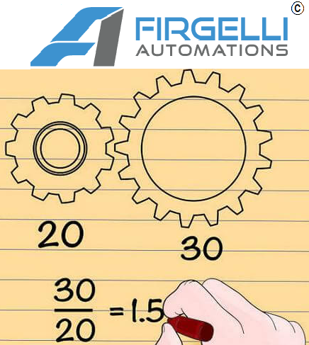
Understanding Gear Ratios: The Mathematics of Mechanical Advantage
The gear ratio is the defining specification of any DC gear motor, determining the relationship between input speed and output torque. Expressed as a ratio such as 10:1 (pronounced "ten to one"), this number tells you how many rotations of the motor shaft are required to produce one complete rotation of the output shaft. In a 10:1 gear motor, the DC motor spins ten times for each single revolution of the final output shaft.
This reduction in speed translates directly to multiplication of torque. In the theoretical ideal, a 10:1 gear ratio would produce exactly ten times the torque of the bare motor while reducing speed to one-tenth. If a motor produces 0.5 Nm of torque at 3000 RPM, the geared output would theoretically deliver 5 Nm at 300 RPM. This mathematical relationship makes it straightforward to calculate the performance you need: determine your required output speed and torque, then work backward to select an appropriate motor and gear ratio combination.
Real-World Efficiency: Why Gear Ratios Aren't Perfect
In practice, gearboxes are not 100% efficient. Every gear mesh involves friction between teeth, bearing friction in the shafts, and energy loss through heat generation. These mechanical losses mean the actual output torque will be less than the theoretical calculation suggests. Gearbox efficiency typically ranges from 70% to 95%, depending on gear type, quality, lubrication, and load conditions.
High-quality planetary gearboxes can achieve 90-95% efficiency per stage, meaning a two-stage reducer might deliver 81-90% overall efficiency (0.90 × 0.90 = 0.81). Worm gears, particularly those with high reduction ratios, may operate at 50-70% efficiency due to the sliding action between worm and gear. These efficiency factors must be incorporated into your design calculations. If you need 5 Nm of output torque and your gearbox operates at 80% efficiency, you'll need a motor capable of producing 6.25 Nm after gear reduction (5 ÷ 0.80 = 6.25).
Efficiency also varies with operating conditions. A gearbox operates most efficiently at moderate speeds and loads. Operating at very low speeds or near-stall conditions typically reduces efficiency. Temperature affects lubricant viscosity, impacting friction and therefore efficiency. When specifying a DC gear motor, always account for a safety margin beyond theoretical calculations to ensure reliable performance under real-world conditions.
Selecting the Appropriate Gear Ratio for Your Application
Choosing the right gear ratio involves balancing speed requirements, torque demands, and motor capabilities. Start by determining your application's required output speed in RPM. Then calculate the torque needed to drive your load, accounting for friction, inertia, and any external forces. Compare these requirements against available motor specifications at various gear ratios.
A higher gear ratio (e.g., 100:1 versus 10:1) provides more torque but slower maximum speed. Lower ratios favor speed over torque. For applications like linear actuators that need to move heavy loads slowly and precisely, high gear ratios of 50:1 to 200:1 are common. For applications requiring faster movement with moderate force—such as conveyor systems or wheeled robots—ratios of 10:1 to 50:1 typically work well.
DC Gear Motors as Rotary Actuators: Controlled Positioning Applications
While many DC gear motors are used for continuous rotation applications, they can also function effectively as rotary actuators—devices that provide precise angular positioning rather than continuous motion. By integrating position feedback sensors and appropriate control electronics, a DC gear motor can accurately position an output shaft to specific angles, hold that position under load, and execute controlled rotational movements.
This rotary actuation capability makes DC gear motors valuable in applications like automated valve control, satellite dish positioning, camera pan-tilt mechanisms, and adjustable furniture. The gear reduction inherent in the motor provides fine position resolution—a 100:1 gear ratio means the motor shaft must rotate 100 times to produce one output revolution, allowing precise angular control when paired with encoder feedback.
Position Feedback and Closed-Loop Control
To function as a true rotary actuator, a DC gear motor typically requires position feedback. Common feedback devices include potentiometers (measuring voltage proportional to shaft angle), optical encoders (counting rotational increments), Hall effect sensors, or absolute position encoders. These sensors provide real-time position data to a controller, which adjusts motor drive signals to achieve and maintain the desired position.
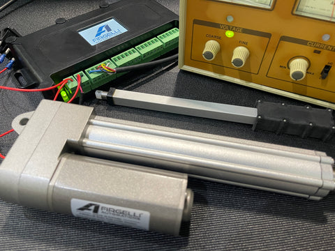
At FIRGELLI Automations, we manufacture feedback actuators with integrated position sensing, applying similar principles to linear motion applications. The same closed-loop control concepts that enable precise linear positioning can be implemented with DC gear motors for rotary applications, using PWM controllers and feedback algorithms to achieve accurate angular positioning.
When to Choose Alternative Rotary Actuator Technologies
While DC gear motors can serve as rotary actuators, certain applications may benefit from specialized alternatives. Stepper motors provide inherent position control through their stepping motion—each electrical pulse produces a precise angular increment without requiring feedback sensors. They excel in applications requiring open-loop positioning accuracy and repeatability. Servo motors combine brushless DC or AC motors with high-resolution encoders and sophisticated controllers, offering exceptional speed, torque, and position accuracy for demanding applications.
DC gear motors with position feedback offer a cost-effective middle ground: better torque-to-weight ratio than steppers, simpler control than servo systems, and adequate precision for many applications. Consider DC gear motors for rotary actuation when you need moderate positioning accuracy, high torque at low speeds, and cost-effective implementation. Choose steppers when you need reliable open-loop positioning with predictable incremental movement. Select servo motors when you require the highest speed, precision, and dynamic performance—accepting the higher cost and complexity involved.
Manufacturing Process: Engineering Precision Into Every Component
The manufacturing of DC gear motors combines precision electrical engineering with mechanical fabrication expertise. Quality manufacturers employ tight tolerances and rigorous testing protocols to ensure reliable performance across the product lifespan. Understanding the manufacturing process provides insight into what differentiates premium gear motors from budget alternatives.
DC Motor Component Fabrication
The process begins with motor component fabrication. The stator housing is typically machined or formed from steel or aluminum alloy, providing structural integrity and a mounting surface for permanent magnets or field windings. Permanent magnets—usually neodymium or ferrite materials—are precisely positioned and secured inside the stator housing to create the stationary magnetic field.
The rotor assembly requires particular precision. Copper wire is wound around the armature core (a laminated iron structure) to create the electromagnetic windings. The number of winding turns, wire gauge, and winding pattern directly affect motor performance characteristics. The commutator—typically made from copper segments separated by insulation—is mounted on the rotor shaft. This component must be precisely balanced and have a smooth surface finish to ensure reliable brush contact and minimize electrical noise.
Carbon-graphite brushes are positioned to maintain constant electrical contact with the rotating commutator. Brush composition affects motor life, efficiency, and electrical noise. High-quality motors use specially formulated brush materials that balance conductivity, wear resistance, and commutator compatibility. Springs maintain appropriate brush pressure against the commutator as wear occurs over the motor's operational life.
Gearbox Manufacturing and Assembly
Gearbox fabrication demands equal precision. Gears are produced through various methods depending on size, material, and volume. Small plastic gears may be injection-molded with carefully designed tooling to ensure proper tooth profiles. Metal gears are typically cut using hobbing, milling, or broaching processes, then heat-treated to increase hardness and wear resistance. Precision grinding operations may follow heat treatment to achieve final tolerances and surface finish.
Gear tooth geometry is critical to performance. Involute tooth profiles—the standard for most applications—ensure smooth power transmission and minimize backlash. Surface finish affects noise generation and efficiency; smoother surfaces reduce friction but require more precise manufacturing. Quality control includes dimensional inspection, tooth profile verification, and surface roughness measurement to ensure specifications are met.
Shafts, bearings, and housing components are manufactured to precise tolerances. Ball or sleeve bearings support the shafts, with bearing selection depending on load requirements, speed, and expected service life. The gearbox housing—typically aluminum alloy or reinforced plastic—is designed to maintain precise gear alignment while providing adequate strength and protection.
Final Assembly, Lubrication, and Testing
During final assembly, the DC motor and gearbox are integrated into a complete unit. Proper lubrication is critical for gearbox longevity and efficiency. High-quality synthetic greases are typically applied to gear teeth and bearings. The lubricant must provide adequate film strength to prevent metal-to-metal contact while maintaining appropriate viscosity across the operating temperature range. Over-lubrication can increase friction and reduce efficiency, while under-lubrication accelerates wear.
Comprehensive testing follows assembly. No-load speed testing verifies that the motor operates at expected RPM without resistance. Load testing measures torque output at various speeds and determines stall torque characteristics. Current draw is measured under different load conditions to verify electrical specifications. Quality manufacturers also conduct endurance testing, running sample units for extended periods under load to identify potential failure modes and verify design life expectations.
This rigorous manufacturing process—from component fabrication through final testing—distinguishes professional-grade DC gear motors from commodity products. When selecting motors for critical applications, consider manufacturers with documented quality control processes and performance testing data to ensure reliable operation.
Applications of DC Gear Motors Across Industries
The combination of compact size, efficient operation, and high torque output makes DC gear motors suitable for an extraordinary range of applications. Their versatility spans from consumer products to industrial automation, from automotive systems to recreational vehicles. Understanding how these motors are applied across industries provides valuable insight for your own projects and applications.
Automotive Applications: From Windshield Wipers to Power Seats
The automotive industry represents one of the largest markets for DC gear motors, with dozens of motors in modern vehicles. Windshield wiper systems are perhaps the most visible application—DC gear motors provide the torque necessary to move wiper arms against wind resistance and water accumulation, while maintaining multiple speed settings through PWM control. The motors must operate reliably across extreme temperatures and withstand years of intermittent use.
Power window mechanisms rely on compact DC gear motors mounted in door panels. These motors must deliver sufficient torque to lift heavy glass panes smoothly while fitting within space constraints. Safety features like anti-pinch detection require precise current monitoring to detect obstructions. Power mirror adjustment uses smaller gear motors with multi-axis positioning to enable driver control of mirror angle via dash-mounted controls.
Seat adjustment systems employ multiple DC gear motors to control position, height, lumbar support, and recline angle. These motors must move substantial loads (the seat plus occupant) slowly and smoothly, requiring high gear ratios and robust construction. Premium vehicles may have eight or more motors per seat to enable fully adjustable ergonomic positioning.
Additional automotive applications include power door locks, sunroof operation, trunk lid lifters, fuel door releases, and HVAC blend door actuators that control air temperature and distribution. The automotive environment demands motors that tolerate temperature extremes, vibration, moisture, and extended service life with minimal maintenance.
RV and Marine Applications: Motion Control for Mobile Living
Recreational vehicles and marine applications extensively utilize DC gear motors for comfort and convenience features. Slide-out mechanisms—which extend living space by moving entire room sections outward—rely on synchronized DC gear motors to push or pull heavy assemblies smoothly. These systems typically employ 12V or 24V motors with worm gear reducers, providing high torque and self-locking properties that prevent unwanted movement when parked on uneven surfaces.
Automatic leveling systems use multiple DC gear motors to adjust jack positions, compensating for uneven parking surfaces. Precise control ensures the RV remains level for comfort and proper appliance operation (particularly refrigerators that rely on gravity-fed cooling systems). Awning controls automate the extension and retraction of shade structures, improving convenience while protecting the awning from wind damage through controlled retraction.
Marine applications face additional challenges from moisture, salt spray, and constant motion. DC gear motors power windlass systems (anchor winches), bimini top deployment, hatch opening mechanisms, and trim tab adjustment. Corrosion-resistant construction and sealed housings are essential in these demanding environments. The reliable 12V or 24V power supply from battery banks makes DC gear motors particularly well-suited for marine applications where AC power may not be available.
Robotics and Automation: Precision Motion for Intelligent Machines
Robotics applications demand precise, repeatable motion control—characteristics that DC gear motors deliver effectively. Wheeled mobile robots use gear motors for drive and steering functions. Differential drive configurations employ two independently controlled motors, enabling precise navigation through speed and direction control of each wheel. The gear reduction provides adequate torque to overcome static friction and accelerate the robot's mass while enabling fine speed control for accurate positioning.
Robotic arms and manipulators utilize DC gear motors at multiple joints to enable multi-axis movement. The high torque-to-weight ratio of modern gear motors allows compact actuator packages that don't overburden the robot's structure. Gear reduction provides fine angular resolution, enabling precise end-effector positioning. For hobbyist and educational robotics, DC gear motors offer an accessible entry point with simple control requirements compared to servo or stepper alternatives.
Industrial automation systems employ DC gear motors in conveyor drives, sorting mechanisms, packaging equipment, and material handling systems. The ability to operate from standard DC power supplies, combined with straightforward speed control through PWM or voltage adjustment, makes these motors easy to integrate into automated systems. While linear actuators handle push-pull motion in many automation applications, DC gear motors excel where continuous or multi-revolution rotation is required.
Home Automation: Creating Smart, Connected Environments
The smart home revolution has created new applications for compact, efficient DC gear motors. Automated window treatment systems use gear motors to raise and lower blinds or rotate louvers, enabling scheduled operation or sun-tracking algorithms that optimize natural light and thermal management. The motors operate quietly—an essential consideration in residential environments—and consume minimal power, allowing battery operation or integration with building management systems.
Smart lock mechanisms employ small DC gear motors to extend and retract deadbolts under electronic control. These motors must provide adequate torque to overcome door frame friction while operating quietly and responding quickly to unlock commands. Battery life considerations favor efficient motor designs with low quiescent power consumption.
Adjustable furniture leverages DC gear motor technology for comfort and ergonomics. Standing desks use motors (often in combination with linear actuators) to adjust height positions, promoting healthier work habits. Adjustable beds employ multiple motors to control head and foot positioning independently. These applications require smooth, quiet operation with the ability to support substantial loads while maintaining position under static load.
Other home automation applications include automated pet feeders, robotic vacuum cleaners, garage door openers, and motorized camera sliders for photography enthusiasts. The continuing growth of IoT devices and smart home integration will likely expand DC gear motor applications further as manufacturers seek compact, efficient actuation solutions.
Controlling DC Gear Motors: Speed, Direction, and Precision
Effective control of DC gear motors requires understanding both the electrical characteristics of the motor and the control techniques available. Proper control enables precise speed regulation, smooth acceleration and deceleration, bidirectional operation, and efficient power usage. Whether you're implementing a simple on-off control or sophisticated closed-loop positioning, selecting appropriate control methods is essential for successful project implementation.
Pulse Width Modulation (PWM): Efficient Speed Control
Pulse Width Modulation stands as the most common and efficient method for controlling DC gear motor speed. PWM rapidly switches the motor power on and off at a fixed frequency (typically 1 kHz to 20 kHz), varying the ratio of on-time to off-time (the duty cycle). A 50% duty cycle delivers half the average voltage to the motor compared to continuous power, resulting in approximately half the motor speed. A 75% duty cycle delivers three-quarters voltage and proportionally higher speed.
The advantage of PWM over simple voltage reduction (using resistors or linear regulators) is efficiency. During the on-time, the motor receives full voltage through low-resistance switching transistors, minimizing power loss. During off-time, no current flows and no power is consumed by the control circuit. This switching approach wastes minimal energy as heat, extending battery life in portable applications and reducing thermal management requirements.
Implementing PWM control requires a switching element (typically a MOSFET transistor), a PWM signal generator (often a microcontroller or dedicated timer IC), and a flyback diode to protect against voltage spikes from motor inductance. Most Arduino boards and similar microcontroller platforms include built-in PWM outputs, making it straightforward to implement speed control in DIY projects. The PWM frequency should be high enough that motor inductance smooths the pulsed current into relatively continuous flow, but not so high that switching losses become significant—the 5-20 kHz range works well for most small to medium DC gear motors.
H-Bridge Circuits: Bidirectional Control
An H-bridge circuit enables bidirectional control of a DC motor by allowing current flow in either direction through the motor windings. The circuit consists of four switching elements (typically MOSFETs) arranged in an H configuration, with the motor forming the crossbar of the H. By selectively activating pairs of switches, current can flow left-to-right or right-to-left through the motor, reversing the magnetic field interaction and therefore the rotation direction.
The four switching states are: forward rotation (top-left and bottom-right switches closed), reverse rotation (top-right and bottom-left switches closed), braking (both bottom switches closed, shorting the motor terminals), and coast (all switches open, allowing the motor to spin freely). PWM speed control can be integrated with H-bridge direction control by PWM-switching the active switch pair, enabling both variable speed and direction control from a single circuit.
Integrated H-bridge driver ICs simplify implementation by incorporating the switching transistors, protection circuitry, and control logic in a single package. Popular drivers like the L298N, L293D, or modern alternatives like the DRV8833 or TB6612FNG handle the complexity of proper switch timing, prevent dangerous shoot-through conditions (both top and bottom switches on simultaneously), and provide thermal protection. These drivers typically accept simple logic inputs for direction and PWM speed signals, making them ideal for microcontroller-based projects.
For projects requiring control boxes or remote controls, H-bridge circuits enable the bidirectional operation essential for applications like motorized blinds, adjustable furniture, or robotic systems. When paired with limit switches or position feedback, H-bridge control enables precise positioning similar to the control systems used in our TV lifts and linear actuator products.
Dedicated Motor Controllers and Driver Modules
For applications requiring sophisticated control or higher power handling, dedicated motor controller modules offer significant advantages over discrete component designs. These controllers integrate power switching, protection features, and often microprocessor-based control algorithms in ready-to-use packages. Features may include adjustable current limiting (protecting both motor and power supply from overcurrent damage), thermal shutdown (preventing component failure from overheating), and under-voltage lockout (preventing erratic operation when supply voltage drops).
Advanced controllers provide closed-loop speed regulation, using motor back-EMF (electromotive force) or encoder feedback to maintain constant speed despite varying loads. This feature proves valuable in applications like conveyor systems or robotic drives where consistent speed is important regardless of load variations. Some controllers offer programmable acceleration and deceleration curves, enabling smooth motion profiles that reduce mechanical stress and improve user experience.
When selecting a motor controller, verify that current and voltage ratings exceed your motor's requirements with adequate safety margin. Continuous current rating should be at least 1.5 times your motor's typical operating current, with peak current capability handling stall or startup conditions. Voltage rating must accommodate your supply voltage plus any transient spikes. For battery-powered applications, consider controllers with low quiescent current draw to maximize battery life.
The integration of appropriate power supplies with your motor controller is crucial for reliable operation. Ensure the power supply can deliver adequate current for your motor's demands, with sufficient margin for startup inrush and any other system loads. Regulated supplies maintain consistent voltage despite load changes, improving speed control accuracy and motor performance consistency.
Selecting the Best DC Gear Motor for Your Application
Choosing the optimal DC gear motor requires systematic evaluation of your application requirements against available motor specifications. A methodical selection process ensures you don't over-specify (wasting cost and space on excessive capability) or under-specify (resulting in poor performance or premature failure). Consider these essential factors in your selection process.
Calculating Torque Requirements
Torque represents the rotational force the motor must produce to drive your load. Accurately calculating required torque is critical—underestimate and your motor will stall or overheat; overestimate significantly and you'll pay for unnecessary capability. Start by identifying all forces resisting motion: load weight, friction, inertia, and any external forces (gravity, wind resistance, etc.).
For rotational loads, calculate the moment of inertia and required angular acceleration to determine the torque needed to overcome inertia. For loads involving linear motion (like raising a weight via a pulley or leadscrew), calculate the force required and multiply by the effective radius to convert to torque. Don't forget to account for friction in bearings, guides, or sliding surfaces—friction can consume a significant portion of available torque, particularly in poorly lubricated or heavily loaded mechanisms.
Include a safety factor in your torque calculations. Typical practice suggests multiplying calculated torque by 1.5 to 2.0 to account for efficiency variations, load uncertainties, and component tolerances. This margin ensures reliable operation under real-world conditions and provides reserve capacity for startup transients when static friction exceeds running friction.
Motor torque specifications typically include rated (continuous) torque and stall torque. Rated torque represents what the motor can deliver continuously without overheating. Stall torque is the maximum torque available at zero speed—essentially the motor's peak capability, but operating at stall generates maximum current and heat, sustainable only briefly. Design your system to operate at no more than 70-80% of rated torque for continuous operation, reserving higher torque capacity for startup and peak load conditions.
Determining Speed Requirements
Speed requirements should reflect both maximum operating speed and speed control range needed. Specify the desired output speed in RPM (revolutions per minute) for the final output shaft. If your application involves linear motion via pulleys, leadscrews, or rack-and-pinion mechanisms, convert linear speed requirements to rotational speed based on the mechanical advantage of your conversion mechanism.
Consider whether your application requires variable speed control or operates at fixed speed. Variable speed applications need motors with good torque characteristics across the speed range and appropriate control electronics. For applications requiring multiple discrete speeds, ensure your motor and controller can reliably maintain each required speed point.
Don't overlook acceleration and deceleration requirements. If your application requires rapid speed changes, the motor must provide adequate torque to overcome load inertia during acceleration, and your mechanical design should include appropriate braking methods. Some applications benefit from soft-start capability—gradual acceleration that reduces mechanical stress and extends component life, particularly important in high-inertia systems.
Efficiency and Power Consumption
Motor efficiency directly impacts power consumption, battery life in portable applications, and heat generation. DC gear motor efficiency is the product of DC motor efficiency and gearbox efficiency. Quality motors achieve 70-85% overall efficiency, while budget options may deliver only 40-60% efficiency—a significant difference in power consumption and thermal management requirements.
For battery-powered applications, efficiency directly translates to operating time. A 75%


