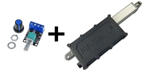
Linear Actuator Speed Control

Linear actuators play a critical role in operations within various sectors, including healthcare, manufacturing, agriculture, automotive among others; hence the need for greater precision and accuracy is essential. Linear actuator speed controllers offer optimal control mechanisms to regulate motion at desired velocities as per the application requirements.
The main functions of linear actuator speed controllers are regulating voltage input supplied to an electric motor or actuator while still accommodating load requirements at maximal force output capacity - thus ensuring greater efficiency within dynamic systems.
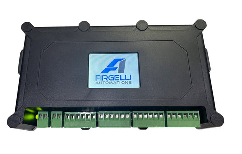
Controlling linear actuator speeds requires sophisticated mechanisms such as implementing a velocity control loop which involves feedback loops obtained from embedded sensors that detect changes in position or velocity--this helps produce optimal outcomes through calibration. FIRGELLI's Actuator Control Board features its own built-in Speed control feedback loop that establishes optimal conditions for operation while ensuring precise movements for your system advancements.
FIRGELLI's Actuator Control board does have its own built-in Speed control feedback loop if you do require a feedback closed loop system for controlling speed very accurately. This control box can ony be used with Linear Actuators that have built in Feedback sensors, soch as Hall sensro or Optical sensor, as it needs these sensors to measure speed of the Acuator.
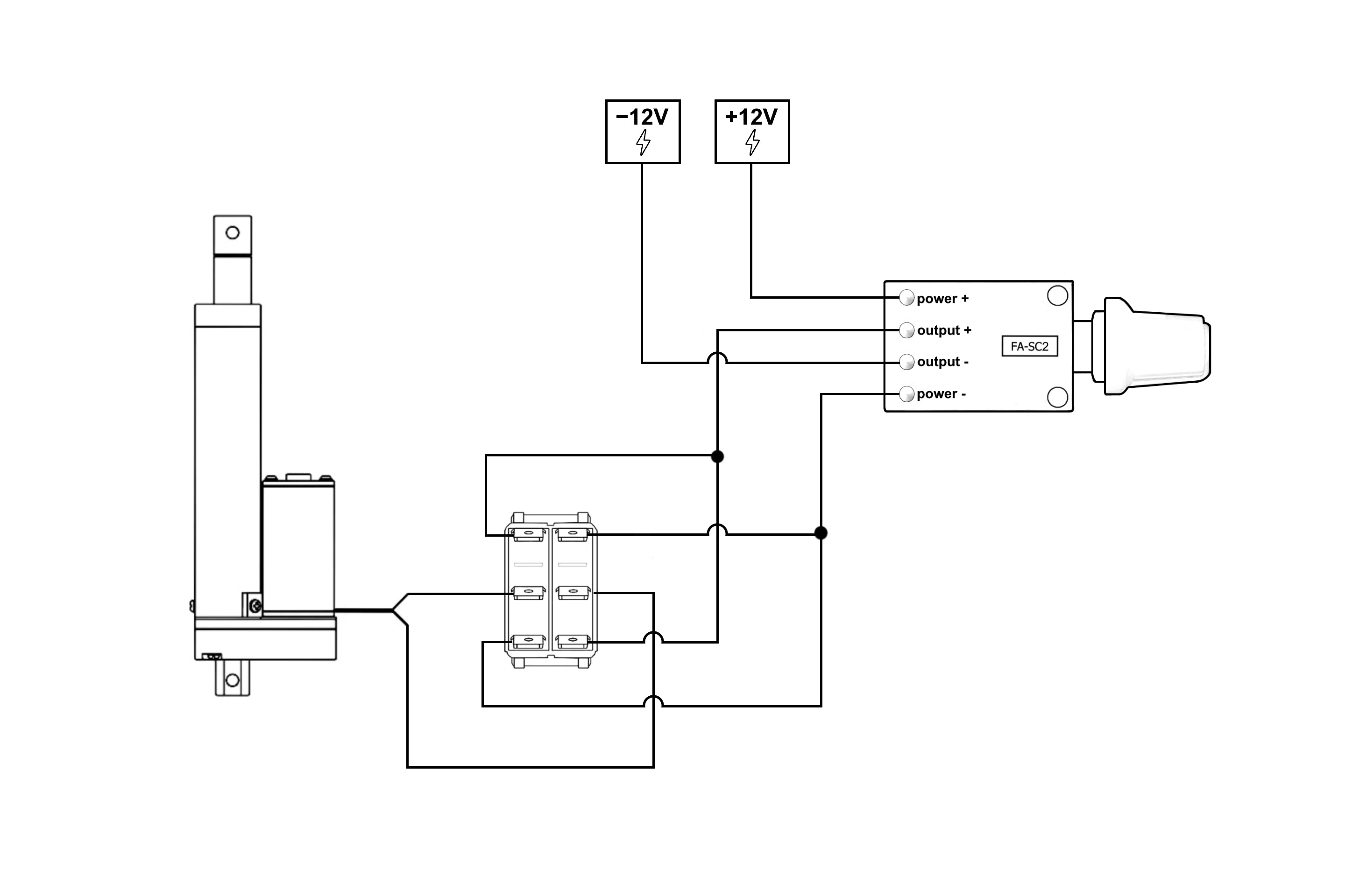
To ensure precision and avoid errors, linear actuators governed by speed controllers continuously monitor and reassess their velocities. The following wiring diagram illustrates how to connect a linear actuator to a rocker switch and speed controller for optimal performance and control.
Wiring Diagram for a speed controller and an actuator

FEED-FORWARD CONTROL
In the context of linear actuators and speed control, feed-forward control is a crucial concept. This approach operates under the assumption that, as the controller, the user can accurately predict the speed controller's output and make any necessary adjustments accordingly. The primary purpose of a control loop for speed regulation is to optimize the actuator's velocity to align with the requirements of a specific task. Provided that all variables remain constant, feed-forward control enables users to make informed predictions regarding the relationship between the actuator's duty cycle and its velocity, based on sensor values per second.
By calculating the duty cycle, users can accurately attain the desired velocity while minimizing errors in estimation. This approach mitigates the risk of overshooting and missing the target entirely, or prematurely stopping before reaching the target, thus undermining the fundamental objective of utilizing a linear actuator.
How a DC speed controller controls the speed of an actuator
A DC speed controller that utilizes Pulse Width Modulation (PWM) is a sophisticated electronic device designed to regulate the speed of a DC actuator. PWM is a technique that enables control of the average voltage supplied to a DC motor by rapidly switching the power ON and OFF at a constant frequency. The speed of the DC actuator can be modulated by adjusting the ON time (duty cycle) relative to the OFF time within each cycle.
Here's an overview of how a DC speed controller using PWM operates to control the speed of a DC actuator:
- Frequency: The PWM controller generates a constant frequency square wave signal, which consists of alternating ON and OFF periods. This frequency is typically high enough that the actuator's motor does not perceive the switching action, resulting in smooth speed control.
- Duty Cycle: The duty cycle refers to the percentage of time the signal remains in the ON state during a single cycle. By varying the duty cycle, the average voltage supplied to the actuator's motor can be controlled. A higher duty cycle corresponds to a higher average voltage, leading to faster actuator speed, while a lower duty cycle results in a lower average voltage and, consequently, slower actuator speed.
- Modulation: As the user or an automated system adjusts the desired speed of the DC actuator, the PWM controller modifies the duty cycle accordingly. This ensures that the appropriate average voltage is supplied to the actuator, enabling precise control over its speed.
- Efficiency: Since the PWM speed controller rapidly switches between fully ON and fully OFF states, energy losses in the form of heat are minimized. This makes PWM a highly efficient method for controlling the speed of a DC actuator.
In summary, a DC speed controller that employs PWM works by generating a square wave signal with a constant frequency and varying duty cycle. By adjusting the duty cycle, the controller modulates the average voltage supplied to the DC actuator's motor, allowing for precise control over its speed while maintaining high energy efficiency.
Why would you want to use a Speed controller?
-
Precision control: The primary benefit of a speed controller is its ability to deliver precise control over the actuator's speed. This feature enables people to fine-tune the velocity of the actuator, ensuring it operates optimally for the specific task or application at hand. By achieving the desired speed with accuracy, you can enhance the overall performance and effectiveness of the system.
-
Adaptability: Different applications often demand varying speed requirements or necessitate adjustments during operation. The FIRGELLI speed controller provide you with the flexibility to easily modify and adapt the actuator's speed to meet the unique demands of each application. This adaptability empowers engineers to optimize system performance in diverse scenarios.
-
Smooth operation: Speed controllers, particularly those employing Pulse Width Modulation (PWM) technology which most proper speed controllers do, offer the advantage of delivering smooth and consistent control over the actuator's speed. This smooth operation is crucial as it minimizes mechanical stress and wear on the actuator, thereby extending its service life.
-
Synchronization: Certain applications need synchronized movement among multiple actuators. In such cases, speed controllers play a pivotal role in maintaining consistent speed across all the actuators involved. This synchronization ensures precise coordination and harmonious operation, resulting in optimized performance and functionality of the system as a whole.
What is the high pitch sound you hear coming from the speed controller as you turn the speed lower and lower?
The high-pitched sound you hear coming from the speed controller as you turn the speed lower and lower is typically caused by the switching frequency of the Pulse Width Modulation (PWM) technique used to regulate the actuator's speed.
PWM involves rapidly switching the power supply to the motor ON and OFF at a constant frequency. When the speed is reduced, the duty cycle (the percentage of time the signal is in the ON state) decreases, causing the motor to receive less average voltage. In some cases, the PWM frequency or its harmonics can fall within the audible range of human hearing (20 Hz to 20 kHz).
The sound may be generated due to the vibration of the motor coils or other components within the speed controller, which resonate at the PWM frequency or its harmonics. This vibration is caused by the rapid expansion and contraction of the magnetic field generated by the electric current in the motor coils as they switch between ON and OFF states.
As the speed is turned lower, the duty cycle decreases, and the motor receives less power during each switching cycle. This change in power can cause the audible noise to become more pronounced. Additionally, certain resonant frequencies of the system may be more susceptible to producing audible noise, depending on the mechanical and electrical characteristics of the motor and speed controller.


